Non Contact Infrared Body
Foreword
The non contact Infrared body thermometer operating Instructions intend to provide the necessary information for proper operation of HTD8823US thermometer model. Only body mode was reviewed and certified by notified body. General knowledge of Infrared thermometer and an understanding of the features and functions of the HTD8823US thermometer model are prerequisites for proper use. The HTD8823US is a medical device, and can be used repeatedly with using life is 5 years. And the shelf life of HTD8823US is 5 years too. Please read the manual first before using it, if not fully understand the usages, please stop using the thermometer.
NOTICE
Purchase or possession of this device does not carry any express or implied license to use with replacement parts which would, alone or in combination with this device, fall within the scope of one of the relating patents.
For further information contact:
Hetaida Technology Co., Ltd.
Adds: 4F, BaiShiDa High-Tech Park, XiangDong Industrial Area, DaLingShan Town,
DongGuan City, Guangdong, China
Tel: +860769-82658050
Fax: +86 0769-82658050
Contact: Tom. Chen
E-mail: [email protected]
Company Name: Wellkang Ltd
Company Address: 16 Castle St, Dover, CT16 1PW, UK
Tel: +44 (20)30869438, 32876300
Fax: +44(20)76811874
Web: www.CEmark.com, www.CE-marking.com, www.CE-marking.eu,
Email: [email protected]
About this manual edition
Current Updated Edition/Revision: A.1, April,13rd, 2020;
Safety Information
This device may only be used for the purposes described in these instructions. The manufacturer cannot be held liable for damage caused by incorrect application.
The non contact infrared body thermometer is designed to minimize the possibility of hazards from errors in the software program by following sound and light engineering design processes, Risk Analysis and Software Validation.
Warnings are identified by the WARNING symbol shown above.
- The Non Contact Infrared Body Thermometer is to be operated by consumers in the household environment, nursery school and doctor in clinics. This manual, accessories, Directions for Use, all precautionary information, and specifications should be read before use.
- This product is designed to measure human body temperature on the forehead. Do not use it for any other purpose.
- This product is intended in the home setting and primary care setting as screening tool.
- Do not use the thermometer if it malfunctions or has been damaged in any matter.
When the ambient temperature of the thermometer changes too much, such as moving the Thermometer from one place of lower temperature to another place of highertemperature, Allow the thermometer to remain in a room for 30 minutes where the temperature is between 5°C to 40°C (41°F – 104°F). - Remove primary batteries if equipment is not likely to be used for long time.
- This product is not waterproof, do not be immersed in water or other liquid; If cleaning and disinfection, please follow the “Care and Storage” section requirements.
- Do not touch the sensor of infrared detection with your fingers.
- If a cold compress on the forehead fever patients, or take other measures to cool down the temperature data will low, should be avoided in this case to measure body temperature.
- This product must be operated in a stable environment, if the ambient environment was mutations, please should be note whether there is fog on the sensor, if any, before using accordance with the “Care and Storage” section to removing the fog.
- Do not near strong electrostatic field or strong magnetic fields, thus avoiding the impact on the accuracy of the measurement data.
- Do not mix the old and new batteries to avoid damage to the product.
- It may affect the accuracy of measurements when the forehead is covered by hair, perspiration, cap or scarf.
- The measuring result of this product is only for your reference. If you have any doubt, please measure the temperature in other methods.
![]() The device should be kept out of the reach of children/pets. When not in use, store the device in a dry room and protect it against extreme moisture, heat, lint, dust and direct sunlight. Never place any heavy objects on the storage case.
The device should be kept out of the reach of children/pets. When not in use, store the device in a dry room and protect it against extreme moisture, heat, lint, dust and direct sunlight. Never place any heavy objects on the storage case.
![]() Do not throw batteries into fire.
Do not throw batteries into fire.
![]() Only use recommended batteries. Do not use rechargeable batteries.
Only use recommended batteries. Do not use rechargeable batteries.
![]() This thermometer will irreplaceable the diagnostic in hospitals.
This thermometer will irreplaceable the diagnostic in hospitals.
![]() Do not fall, disassemble or modify the device.
Do not fall, disassemble or modify the device.
![]() Do not use this device if you think it is damaged or notice anything unusual.
Do not use this device if you think it is damaged or notice anything unusual.
![]() This device comprises sensitive components and must be treated with caution. Observe the storage and operating conditions described in the ‘Technical Specifications’ section.
This device comprises sensitive components and must be treated with caution. Observe the storage and operating conditions described in the ‘Technical Specifications’ section.
![]() Not servicing/maintenance while the thermometer is in use.
Not servicing/maintenance while the thermometer is in use.
![]() When using, shall not touch battery and the patient simultaneously.
When using, shall not touch battery and the patient simultaneously.
![]() Do not use the device if it is damaged/ degraded/loosened in any way. The continuous use of a damaged unit may cause injury, improper results, or serious danger.
Do not use the device if it is damaged/ degraded/loosened in any way. The continuous use of a damaged unit may cause injury, improper results, or serious danger.
![]() Based on the current science and technology, other potential allergic reactions are unknown.
Based on the current science and technology, other potential allergic reactions are unknown.
![]() This equipment needs to be installed and put into service in accordance with the information provided in the ACCOMPANYING DOCUMENTS.
This equipment needs to be installed and put into service in accordance with the information provided in the ACCOMPANYING DOCUMENTS.
Section 1- Overview
Indication for use:
The Non-contact Infrared Body Thermometer, Model: HTD8823US, is an electronic clinical thermometer using an infrared sensor to detect body temperature from the forehead in people of all ages for home setting use.
Description of Non Contact Infrared Body Thermometer
- Device principle and introduction
- The HeTaiDa Non contact infrared body thermometer are hand-held, reusable, battery operated devices, which can measure human body temperature on forehead, the skin temperature on one’s forehead.
- The operation principle is based on Infrared Sensor technology. The IR sensor can output different signal when measuring different object temperature or in different ambient temperature, and the ASIC can turn the signal from IR Sensor to a digital value and display it on the LCD.
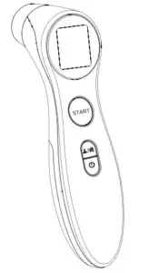
- Description on Controls, Indicators, and Symbols.
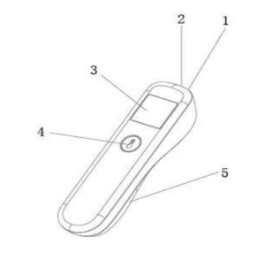
1. IR sensor
2. Position lamp
3. Liquid crystal display (LCD)
4. On/Scan button
5. Battery Cover
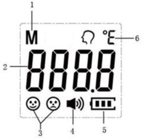
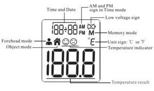
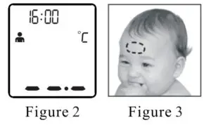
1. Memory indicator
2. Data indicator
3. Indicator of measurement result
4.Speaker
5. Battery indicator
6.Unit
Figure 2: LCD description
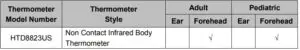
Thermometer Applications
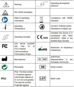
Equipment Symbols
Technical Specifications
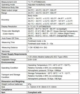
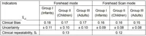
Calculated values of the indicators according to ISO 80601-2-56
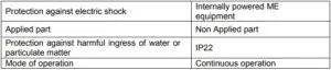
Safety classification of ME EQUIPMENT
Note: Not intended to be sterilized. Not for use in an OXYGEN RICH ENVIRONMENT
Operation
Battery installation
Caution: The Non Contact Infrared Body Thermometer does not operate with dead batteries and does not input outer power. Install new batteries.
- Pull the battery downward, toward the bottom of the Non Contact Infrared Body Thermometer, and remove the battery access door;
- Insert two pieces AAA size batteries according to the “+” and “-”;
- Close the battery cover.
How to Operate
Before Applying the Thermometer
Be sure to read and understand all warnings listed of the instructions before use.
- Forehead mode: press On/Scan button to open the device, the thermometer is aligned with the middle of the forehead to measure body temperature (between the eyebrows above) and keep the vertical distance, press the On/Scan button, the position lamp indicates measurement site with light spot on the forehead, temperature display immediately, see figure 3.

Figure 3-Measuring position and distance - Forehead Scan mode: gently position the probe flush (flat) on the center of the forehead, midway between the eyebrow and the hairline. Press and hold the On/Scan button. Lightly slide the thermometer across the fore-head keeping the sensor flat and in contact with the skin until you reach the hairline, release the On/Scan button and remove the thermometer from the head, then the temperature will display on the screen. The whole process takes 3~10 seconds.
- When the ambient temperature of the thermometer changes too much, such as moving the Thermometer from one place of lower temperature to another place of higher temperature, Allow the thermometer to remain in a room for 30 minutes where the temperature is between 5°C to 40°C.
- The ambient temperature around the test person should be stable, should keep away from the larger flow fan, air-conditioning vents and so on.
- When people moving from one place of lower temperature to another place of higher temperature, should at least remain in the test environment more than 5 minutes, to be consistent with the ambient temperature after the re-measurement.
- Wait at least 1 second for the next measurement. If the continuous measurement of five times, it is recommended to wait at least 30 seconds and then continue measurement.
- You cannot use the thermometer in place where the sun is strong.
General Setup and Use
Start measuring
- Turn on the thermometer by pressing the On / Scan button. The thermometer will perform self-test with all segments displayed (Figure 4) for 1 second.
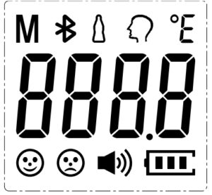
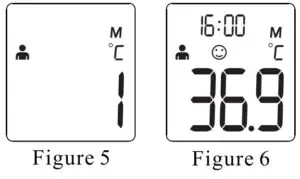
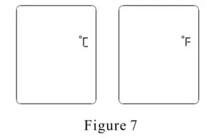
Figure 4- All segments displayed - And then show last measurement value (Figure 5), and back to ready display for measurement displayed ‘- – – -‘. (Figure 6)
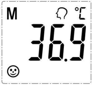
Figure 5 – Last memory display
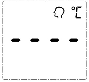
Figure 6 – Ready display for measurement - Forehead mode: Align staff forehead to keep the distance, and then press the On/Scan button, the position lamp indicates measurement site with light spot on the forehead, and start the measurement, read the data.
- Forehead scan method: position the probe flush (flat) on the center of the forehead, midway between the eyebrow and the hairline. Press and hold the On/Scan button. Lightly slide the thermometer across the fore-head keeping the sensor flat and in contact with the skin until you reach the hairline, release the On/Scan button and remove the thermometer from the head, then the temperature will display on the screen. The whole process takes 3~10 seconds.
Note:
- After full display over, you will hear a rattle or “bibi” four times, which means that the measurements have been completed, while the target value of the measured temperature is displayed on the LCD, while backlit display according to the appropriate setting among the three colors green, yellow, orange one of. And theGreen means ready for next measurement. When 37.5°C ~ 38.5°C, it’s yellow,
means slight fever warning. Please pay attention to body temperature. When the body temperature is 38.6°C or above, it’s orange, means high fever. Please take action to cool down or go for a doctor. - To ensure the accuracy of the measurement, wait at least 30 seconds after 5 consecutive measurements
Unit Set ( Only applicable for HTD8823US)
Turn on the thermometer by pressing the On/Scan button. The thermometer will perform self-test with all segments displayed for 1 second, and then show last measurement value. During last measurement show, press and hold on On/Scan button to enter unit switch display. When display unit what you want, release On/Scan button saving the setting, and back to ready display for measurement displayed ‘- – – -‘.
Troubleshooting
Replacing the Battery
- Open and release battery cover following indicator on the surface of shell. Before changing the battery being sure the system is already power off.
- Remove the batteries and replace with 2 new one, type AAA, Make sure align properly as indicated inside the battery compartment
- Slide the battery cover back in until it snaps in place.
Do not dispose of used batteries in household waste. Take them to special local collection sites. - In case, if system is latched up after changing battery. You may not follow up theprocess of rule one. Just take off battery, waiting 30 sec, then load battery again.
Warning
- The typical service life of the new and unused batteries is 2000 measurements for the operation time is 18s.
- Only use the recommended batteries, do not recharge non-rechargeable batteries and do not burn them.
- Remove the batteries if the thermometer is not to be used for a long period.
Cleaning, Care and Storage
The lens is very delicate.
It is very important to protect the lens from dirt and damage. This thermometer is for single patient reuse, you may use 70% isopropyl alcohol wipes to gently clean thethermometer after each use.
Rubbing device (including markings) by hand without undue pressure with 70% isopropyl alcohol, especially skin contact part, such as the probe, shell, LCD for 15s after each measurement, wiping sensor of thermometer (which is in the center of probe surrounded by ABS case) gently for 3s
using a cotton swab wetted 70% isopropyl alcohol if dirty.
Always keep the thermometer a within the storage temperature and humidity range as specified.
It is recommended to store the thermometer in a dry location free from dust.
Always keep the thermometer within the storage temperature range (- 20°C to 55°C or – 4°F to 131°F) and humidity range (≤ 95% non-condensing)
It is recommended to store the thermometer in a dry location free from dust. Do not expose the thermometer to direct sunlight, high temperature/ humidity or any extreme environment, otherwise the function will be reduced.
When the ambient temperature of the thermometer changes too much, such as moving the thermometer from one place of lower temperature to another place of higher temperature, allow the thermometer to remain in a room for 30 minutes where the temperature is between 5°C to 40°C.
Disposal
- Used batteries should not be disposed of in the household rubbish. Used Batteries should be deposited at a collection point.
- At the end of its life, the appliance should not be disposed of in household rubbish. Enquire about the options for environment-friendly and appropriate disposal. Take local regulations into account.
Warranty
Our company warrants Non Contact Infrared Body Thermometer at the time of its original purchase and for the subsequence time period of one year.
The warranty does not cover the followings:
- The device series number label is torn off or cannot be recognized.
- Damage to the device resulting from misconnection with other devices.
- Damage to the device resulting from accidents.
- Changes performed by users without the prior written authorization of the company.
- Batteries and packaging are not covered under warranty.
When asked to provide warranty service, you must have a purchase date and purchase stamp dealers (including dealers name and address) of the warranty card. Be sure to ask the dealer to purchase this product signature on the warranty card. When asked to provide warranty service, please put the product to get our distribution points for repair. Products outside the warranty expires, will be charged accordingly.
Note
- If you have any problems with this device, such as setting up, maintaining or using, please contact with SERVICE PERSONNEL of HeTaiDa Technology Co., Ltd. Don’t open or repair the device by yourself.
- Please report to HeTaiDa Technology Co., Ltd. if any unexpected operation or events occur.
- Calibration needed to ensure proper function for every two years or after device impact.
- The patient is an intended operator. The patient can measure and change battery. Under normal circumstances and maintain the device and its accessories according to the user manual.
EMC Declaration
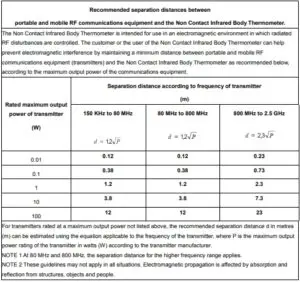
- This equipment needs to be installed and put into service in accordance with the information provided in the ACCOMPANYING DOCUMENTS; This product needs special precautions regarding EMC and needs to be installed and put into service according to the EMC information provided, and this unit can be affected by portable and mobile RF communications equipment.
- Caution: Do not use a mobile phone or other devices that emit electromagnetic fields, near the unit. This may result in incorrect operation of the unit.
- Caution: This unit has been thoroughly tested and inspected to assure proper performance and operation!
- Caution: this machine should not be used adjacent to or stacked with other equipment and that if adjacent or stacked use is necessary, this machine should be observed to verify normal operation in the configuration in which it will be used.
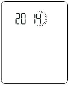
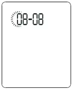
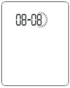
5. Set the month Press and realase the START BUTTON to advance one month until the correct month appears. After the month is set, press BUTTON, the Date figure is flashing automatically.
6.
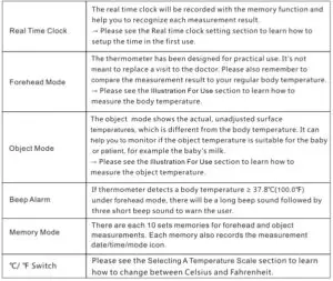
Memory Mode
- The Memory Mode can be accessed ether in forehead mode or object mode: When the thermometer has been turned on and followed by Figure 2/4 or finished testing, press and hold the BUTTON for three seconds. The letter M will appear in the center right corner of the display. (See Figure 5)
- The thermometer will automatically memorize the last 10 temperature readings. Each memory also records the measurement date/time/mode icon. Each time the BUTTON is pressed, the screen displays past readings that correspond with a number 1-10. The number 1 reflects the most recent reading, while the number 10 reveals the oldest reading stored in memory,(See Figure 6)
- In the memory mode,
 mark or
  mark always exist. The user can press the START BUTTON to take new measurements.
Selecting A Temperature Scale
- Temperature readings are available in the Celsius (‘C) or Fahrenheit (“F) scale.
- With the thermometer off, press and hold the START BUTTON for 3 seconds to enter into unit changing mode.
- Press and release START BUTTON to select the unit.
- When the preferred unit on the display, press© BUTTON to exit the unit changing mode.
Care And Cleaning
- The probe window must be kept clean, dry, and undamaged at all times to ensure accurate readings. The accuracy of temperature readings can be affected by damage to the probe window, or the presence of dirt, fingerprints, earwax, dust and other soiling compounds on the probe window. Degraded sensors can degrade performance or cause other problems.
- Periodic cleaning and disinfection of the device following in order to prevent patient cross infection. Please clean and disinfect the thermometer immediately after each use.
For cleaning: 1 )Soak a clean soft cloth in drinking waler, wring ii out and then wipe the then no meter(including probe) no less than 3 times;
2)Then use another clean soft cloth to wipe the residue water on thermometer;
3)Put the thennometer in the original packaging. For disinfection:
1 )Soak a clean soft cloth in drinking water, wring it out and then wipe the thermometer(includ.ing probe) no less than3 times;
2)Thcn use another clean soft cloth to wipe the residue water on thcnnomctcr;
3)Using a clean soft cloth dipped in 70% medical alcohol, wipe the probe 3 times, at least one minute for each time
4 )Using a clean cotton swab dipped in 70% medical alcohol, wipe the sensor window 3times;
5)Wait at least 10 minutes to let the alcohol volatilization and then put the thermometer in the original packaging - Us e a soft, dry cloth to clean the thermometer display and exterior.
- The thermometer is not waterproof. Do not submerge the unit in water when cleaning.
- Store the thermometer in a dry location, free from dust and contamination and away from direct sunlight.
- Strong electromagnetic fields may interfere with the proper operation of the then no meter. The device needs special pre-cautions regarding EMC according to the EMC information.
- Put the thermometer back to the original packaging after using.
Battery Replacement
- Replace battery when” I):) “appears in the upper right corner of LCD display. (See Figure 8)
- Slide battery cover down as shown in Figure 9.
- Remove battery and install 2 new AAA alkaline batteries as shown in Figure 10 .
- Slide battery cover back on.

Figure 8
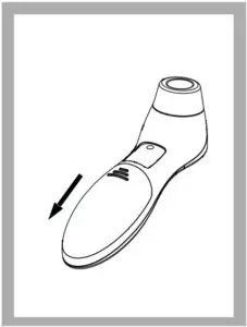
Figure 9
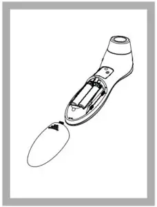
Figure 10
Specifications
Troubleshooting
Calibration
The thermometer is initially calibrated at the time of manufacture. If the thermometer is used according to the use instruction, periodic readjustment is not required. However, We recommends checking calibration every two years or whenever clinical accuracy of the thermometer is in question. Please send the complete device to the dealers or manufacturer.
The above recommendations do not supersede the legal requirements.
The user must always comply with legal requirements for the control of the measurement, functionality, and accuracy of the device which are required by the scope ofrelevant laws, directives or ordinances where the device is used.
A clinical summary and procedures for checking calibration are available upon request.(Turn on the thermometer and press the power button long time until entering into calibrate mode, software version will be displayed.)
Service
The thermometer has a limited one year warranty. Do not attempt to disassemble or repair the thermometer by yourself. Should service be required during or after the warranty period you must contact the manufacturer. Repackage the thermometer carefully in its original packaging or securely pack to avoid damage during shipping. Include the original sales slip indicating the date of purchase, a note describing the problem, and your return address. Send the thermometer prepaid and insured. The lay operator or lay responsible organization should contact the manufacturer or the manufacturer1 s representative:
– for assistance, if needed, in setting up, using or maintaining the thermometer; or
– to report unexpected operation or events.
Maoufacturer:
IOYTECH HEALTHCARE CO. LTD.
No.365, Wnzhou Rond, Yuhang EcOTiomic Development Zone, 3 l ll 00 H11ngzh011. , China
Telephone: +86-571-81957767
Fax: +86-571-81957750
Made in China
Warranty
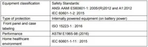
This appliance conforms to the following standards: ASTM El 965-98 Standard Specification for Infrared Thermometers for Intermittent Determination of Patient Temperature, ISO 80601-2-56 Medical electrical equipment-Part 2-56: Particular requirements for basic safety and essential performance of clinical thermometers for body temperature measurement, JEC 60601-1-11 Medical electrical equipment-Part 1-11: General requirements for basic safety and essential performance -Collateral Standard: Requirements for medical electrical equipment and medical electrical systems used in the home healthcare environment and complies with the requirements ofIEC 60601-l-2(EMC), AAMIANSI ES60601-l(Safety) standards. And the manufacturer is ISO 13485 certified.
Thermometer is warranted by manufacture to be free from defects in material and workmanship under normal use and service for a period of one year from the date of delivery to the first user who purchases the instrument. This warranty does not cover batteries, damage to the probe window, or damage to the instrument caused by misuse, negligence or accident, and extends to only to the first purchaser of the product.
FCC Information
Caution: Changes or modifications to this unit not expressly approved by the party responsible for compliance could void the user authority to operate the equipment.
*Note:
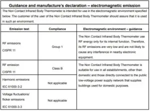
This equipment has been tested and found to comply with the limits for a Class B digital device, pursuant to Part 15 of the FCC Rules. These limits are designed to provide reasonable protection against harmful interference in a residential installation. This equipment generates, uses, and can radiate radio frequency energy. If this equipment does cause harmful interference to radio or television reception, which can be determined by turning the equipment off and on, the user is encouraged to try and correct the interference by one or more of the following measures:
– Reorient or relocate the receiving antenna.
– Increase the distance between the equipment and the receiver.
– Connect the equipment to an outlet on a circuit different from that to which the receiver is connected.
– Consult the dealer or an experienced radio/TV technician for help.
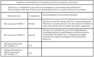
Electromagnetic Compatibility Information
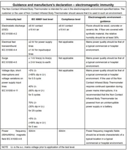
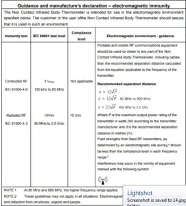
The device satisfies the EMC requirements of the international standard IEC 60601-1-2. The requirements are satisfied under the conditions described in the table below. The device is an electrical medical product and is subject to special precautionary measures with regard to EMC which must be published in the instructions for use. Portable and mobile HF communications equipment can affect the device. Use of the unit in conjunction with non-approved accessories can affect the device negatively and alter the electromagnetic compatibility, The device should not be used directly adjacent to or between other electrical equipment.
Table 1
Warning:
- The Use of this equipment adj11eent to or stacked with other equipment should be avoided because it could result in improper operation. If such use is necessary, this equipment and the other equipment should be observed to verify that they l!Ie operating normally.)
- Portable RF communications equipment (including peripherals such as antenna cables and ex.lernal anlennas) should be used no closer than 30 cm (12 inches) to any part of the [ME EQUIPMENT or ME SYSTEM], including cables specified by the manufacturer. Otherwise, degradation oftbe performance of this equipment could result.
Table 2
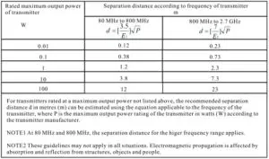
Table 3
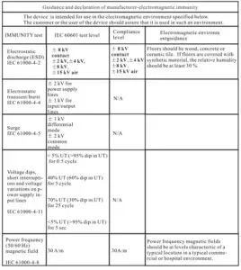
Table 4

Compliance Statements
FEDERAL COMMUNICATIONS COMMISSION INTERFERENCE
STATEMENT
This equipment has been tested and found to comply with the limits for a Class A digital device, pursuant to Part 15 of the FCC Rules. These limits are designed to provide reasonable protection against harmful interference when the equipment is operated in a commercial environment. This equipment generates, uses, and can radiate radio frequency energy and, if not installed and
used in accordance with the instruction manual, may cause harmful interference to radio communications. Operation of this equipment in a residential area is likely to cause harmful interference in which case the user will be required to correct the interference at his own expense.
The device complies with Part 15 of the FCC Rules. Operation is subject to the following two conditions: (1) this device may not cause harmful interference, and (2) this device must accept any interference received, including interference that may cause undesired operation.
FCC Caution
Any changes or modifications not expressly approved by the party responsible for compliance could void the user’s authority to operate this equipment.
Warning
Operation of this equipment in a residential environment could cause radio interference.

Industry Canada Statement
This Class A digital apparatus complies with Canadian ICES-003.
CAN ICES-003 (A)/NMB-003 (A)
HDMI Trademark Statement
The terms HDMI, HDMI High-Definition Multimedia Interface, and the
HDMI Logo are trademarks or registered trademarks of HDMI Licensing
Administrator, Inc.

RoHS
This product is RoHS compliant.
About this Manual
This User Manual is provided to help you get the most from your system. It
covers all aspects of installation, configuration and operation. An overview of the information found in the manual is provided below.
Chapter 1, Introduction, introduces you to the VE803 system. Its purpose,
features and benefits are presented, and its front and back panel components are described.
Chapter 2, Hardware Setup, describes how to set up your installation. All necessary steps to prepare for operation are provided.
Chapter 3, Basic Operation, describes how to use the EDID switch and EQ switch to adjust the picture quality.
An Appendix, provides specifications and other technical information regarding the VE803.
Package Contents
The basic VE803 package consists of:
- 1 VE803T HDMI USB Extender
- 1 VE803R HDMI USB Extender
- 1 power adapter
- 1 USB cable (1.8 m)
- 1 mounting kit
- 1 user instructions*
Check to make sure that all the components are present and that nothing got damaged in shipping. If you encounter a problem, contact your dealer.
Read this manual thoroughly and follow the installation and operation procedures carefully to prevent any damage to the unit, and/or any of the devices connected to it.
| * Features may have been added to the VE803 since this manual was published. Please visit our website to download the most up-to-date version. |
User Information
Be sure to register your product at our online support center:
| International | http://eservice.aten.com/ |
For telephone support, call this number:
| International | 886-2-8692-6959 |
| China | 86-400-810-0-810 |
| Japan | 81-3-5615-5811 |
| Korea | 82-2-467-6789 |
| North America | 1-888-999-ATEN ext 4988 1-949-428-1111 |
All information, documentation, and specifications contained in this manual are subject to change without prior notification by the manufacturer. The manufacturer makes no representations or warranties, either expressed or implied, with respect to the contents hereof and specifically disclaims any warranties as to merchantability or fitness for any particular purpose. Any of
the manufacturer’s software described in this manual is sold or licensed as is. Should the programs prove defective following their purchase, the buyer (and not the manufacturer, its distributor, or its dealer), assumes the entire cost of all necessary servicing, repair and any incidental or consequential damages resulting from any defect in the software.
The manufacturer of this system is not responsible for any radio and/or TV
interference caused by unauthorized modifications to this device. It is the responsibility of the user to correct such interference.
The manufacturer is not responsible for any damage incurred in the operation
of this system if the correct operational voltage setting was not selected prior to operation. PLEASE VERIFY THAT THE VOLTAGE SETTING IS CORRECT BEFORE USE.
Conventions
This manual uses the following conventions:
| Monospaced | Indicates text that you should key in. |
| [ ] | Indicates keys you should press. For example, [Enter] means to press the Enter key. If keys need to be chorded, they appear together in the same bracket with a plus sign between them: [Ctrl+Alt]. |
| 1. | Numbered lists represent procedures with sequential steps. |
| ♦ | Bullet lists provide information, but do not involve sequential steps. |
| > | Indicates selecting the option (on a menu or dialog box, for example), that comes next. For example, Start > Run means to open the Start menu, and then select Run. |
 |
Indicates critical information. |
Product Information
For information about all ATEN products and how they can help you connect without limits, visit ATEN on the Web or contact an ATEN Authorized
Reseller. Visit ATEN on the Web for a list of locations and telephone numbers:
| International | http://www.aten.com/ |
| North America | http://www.aten-usa.com/ |
Introduction
Overview
The VE803 HDMI USB Extender extends HDMI signals up to 60 meters from the HDMI source using two Cat 5e cables. It is capable of sending 1080i signals up to 60 meters, and 1080p signals up to 40 meters.
The VE803 is equipped with USB connectors, which allow you to extend any USB device between the units. The USB feature also provides support for touch panel control, allowing you to control the local HDMI source device from the remote display, or control the remote display through the local unit.
The VE803 is ideal for transportation centers, medical facilities, shopping malls or anywhere touch panel control at a kiosk is required. For flexibility and convenience, the VE803 local unit can be powered via the USB cable when connected to an appropriate source device. The VE803 is HDCP compliant, providing an easy and ideal HDMI extender solution for any application
- Uses two Cat 5e cables to connect the local and the remote units
- Extends 1080p by 40m; extends 1080i by 60m
- Superior video quality – HDTV resolutions of 480p, 720p, 1080i, 1080p (1920×1080), VGA, SVGA, XGA, SXGA, UXGA and WUXGA (1920×1200)
- Supports USB touch panels
- 8-segment Equalization adjustment switch optimizes display quality
- Supports Dolby True HD and DTS HD Master Audio
- Built-in 8KV / 15KV ESD protection
- Transparent USB Support – supports all USB 2.0 full speed device (12 Mbps)
- USB 2.0 compatible
- Supports wide screen formats
- HDMI (3D, Deep Color); HDCP compatible – signaling rates up to 2.25 Gbits
- Transmitter unit powered via USB cable
Requirements
The following equipment must be installed on the source device or computer:
- HDMI Type A output connector(s)
- A display device or receiver with an HDMI Type A input connector
- Use HDMI cables to connect the HDMI source and display device to the VE803T and VE803R
- Use two Cat 5e cables to connect the VE803T to the VE803R
- Use standard USB cables with Type-A to Type-B connectors to connect USB devices
| Note: Cables are not included in this package. We strongly recommend that you purchase high-quality cables of appropriate length since this will affect the quality of the audio and video display. Contact your dealer to purchase the correct cable sets. |
Maximum cable distances are as follows:
- 40 m at 1080p @ 24-bit color depth
- 60 m at 1080i @ 24-bit color depth
Components
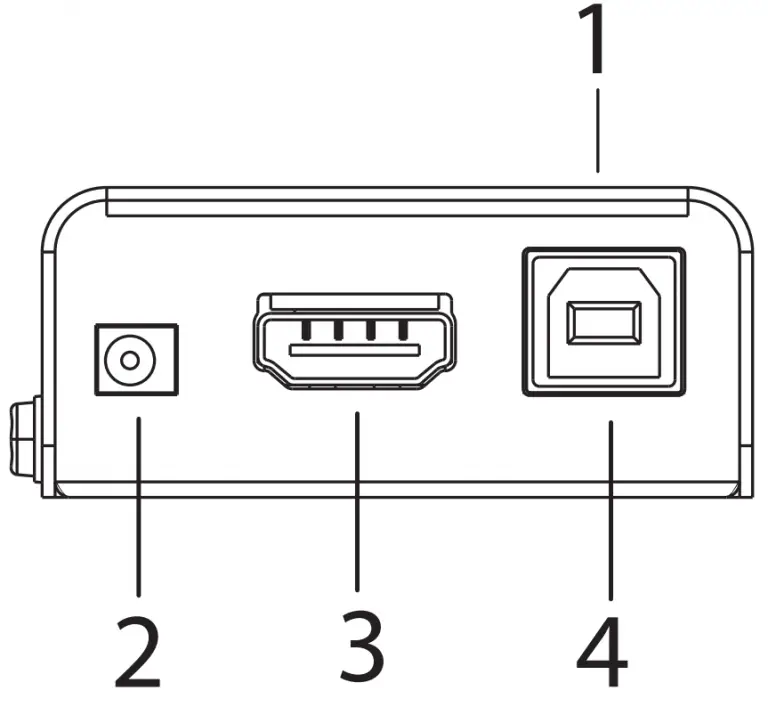
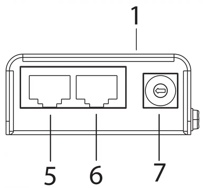
| No. | Component | Description |
| 1 | power LED | Lights (green) to indicate that the unit is receiving power. |
| 2 | power jack | The power adapter cable plugs connects here. |
| 3 | HDMI in | Connect the HDMI source device to this port. |
| 4 | USB Type-B port | Connect the source controller device to this port. |
| 5 | HDMI port | Use a Cat 5e cable to connect the VE803T to the VE803R through this port. This channel is equipped with TMDS and sends the HDMI signal between the two units. |
| 6 | USB port | Use a Cat 5e cable to connect the VE803T to the VE803R through this port. This channel is equipped with DDC and sends the USB signal between the two units. |
| 7 | EDID switch | Use this switch to set the EDID mode (Bypass or Default). |
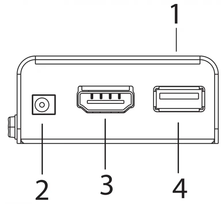
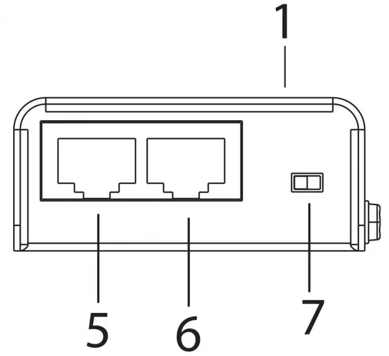
| No. | Component | Description |
| 1 | LEDs | Three LEDs – Power, HDMI, and USB – light (green) when the unit is properly connected to an appropriate source. |
| 2 | power jack | The power adapter cable plugs connects here. |
| 3 | HDMI out | Connect the HDMI display to this port. |
| 4 | USB Type-A port | Connect the display device to this port for controlling the source device. |
| 5 | HDMI port | Use a Cat 5e cable to connect the VE803T to the VE803R through this port. This channel is equipped with TMDS and sends the HDMI signal between the two units. |
| 6 | USB port | Use a Cat 5e cable to connect the VE803T to the VE803R through this port. This channel is equipped with DDC and sends the USB signal between the two units. |
| 7 | EQ switch | This 8-segment switch is used to adjust video quality. |
Hardware Setup
- Important safety information regarding the placement of this device is provided on page 11. Please review it before proceeding.
- Make sure that the power to all devices connected to the installation are turned off. You must unplug the power cords of any computers that have the Keyboard Power On function.
Installation
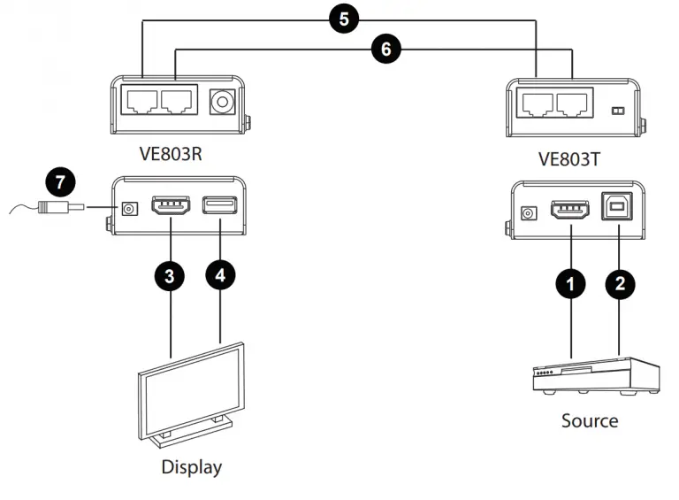
Setting up the VE803 is a matter of plugging in all the cables. Refer to the installation diagram on the next page (the numbers in the diagram correspond to the numbered steps) and do the following:
- Connect one end of an HDMI cable to the HDMI output port of your source device, and connect the other end to the HDMI Input port on the VE803T.
- Using the USB cable provided with this package, connect one end (Type-B connector) to the USB port on the VE803T, and the other end (Type-A connector) to the source device.
Note: The VE803T takes its power from this USB port. If the power supply is not enough to power on the VE803T, the unit can be plugged directly to a power outlet using a second power adapter (not supplied in this package). - Use an HDMI cable to connect your HDMI display to the HDMI Output port on the VE803R.
- Using a USB cable, connect one end (Type-A connector) to the USB port on the VE803R, and the other end to your HDMI display (or another device, such as a touchscreen).
Note: The USB cable for the VE803R is not supplied in this package. - Use a Cat 5e cable to connect the HDMI port on the VE803T to the HDMI port on the VE803R
- Use a second Cat 5e cable to connect the USB port on the VE803T to the USB port on the VE803R.
Note: For the VE803, a second Cate 5e cable is required if you need to use EDID bypass and HDCP authentication. - Using the power adapter supplied with this package, connect the VE803R to a power outlet.
- Turn on the HDMI source and display devices.
Installation Diagram
Basic Operation
Overview
This chapter describes the EDID and Equalization (EQ) switch functions to adjust the HDMI display and obtain the best video quality.
EDID Switch
Extended Display Identification Data (EDID) is a data format that contains a display’s basic information and is used to communicate with the video source/ system. In order to deliver the best video format, the VE803 is able to read the EDID information from the display and determine the best video resolution to send to the video source and program its resolution.
Use the EDID switch on the VE803T to manually switch EDID modes. There are two EDID modes to choose from:
- EDID/DDC Bypass- This mode bypasses the use of EDID / DDC, thus allowing the display information to come directly from the HDMI display to the source device, and determine the best resolution.
- ATEN Default- ATEN’s default EDID setting is sent to the video source to set the display resolution setting for your HDMI display.
Equalization Adjustment
The 8-segment Equalization (EQ) switch located on the VE803R unit is used to adjust the video quality. Use the EQ switch to adjust the equalization strength in order to improve a flickering or blinking image:
- 7 = Strongest EQ
- 0 = Weakest EQ
Appendix
Safety Instructions
- Read all of these instructions. Save them for future reference.
- Follow all warnings and instructions marked on the device.
- This product is for indoor use only.
- Do not place the device on any unstable surface (cart, stand, table, etc.). If the device falls, serious damage will result.
- Do not use the device near water.
- Do not place the device near, or over, radiators or heat registers.
- The device cabinet is provided with slots and openings to allow for adequate ventilation. To ensure reliable operation, and to protect against overheating, these openings must never be blocked or covered.
- The device should never be placed on a soft surface (bed, sofa, rug, etc.) as this will block its ventilation openings. Likewise, the device should not be placed in a built in enclosure unless adequate ventilation has been provided.
- Never spill liquid of any kind on the device.
- Unplug the device from the wall outlet before cleaning. Do not use liquid or aerosol cleaners. Use a damp cloth for cleaning.
- The device should be operated from the type of power source indicated on the marking label. If you are not sure of the type of power available, consult your dealer or local power company.
- To prevent damage to your installation it is important that all devices are properly grounded.
- Do not allow anything to rest on the power cord or cables. Route the power cord and cables so that they cannot be stepped on or tripped over.
- Position system cables and power cables carefully; Be sure that nothing rests on any cables.
- Never push objects of any kind into or through cabinet slots. They may touch dangerous voltage points or short out parts resulting in a risk of fire or electrical shock.
- Do not attempt to service the device yourself. Refer all servicing to qualified service personnel.
- If the following conditions occur, unplug the device from the wall outlet and bring it to qualified service personnel for repair.
♦ The power cord or plug has become damaged or frayed.
♦ Liquid has been spilled into the device.
♦ The device has been exposed to rain or water.
♦ The device has been dropped, or the cabinet has been damaged.
♦ The device exhibits a distinct change in performance, indicating a need for service.
♦ The device does not operate normally when the operating instructions are followed. - Only adjust those controls that are covered in the operating instructions.
Improper adjustment of other controls may result in damage that will require extensive work by a qualified technician to repair.
Technical Support
- For online technical support – including troubleshooting, documentation, and software updates: http://eservice.aten.com
- For telephone support, see Telephone Support, page vi:
| Email Support | [email protected] | |
| Online Technical Support | Troubleshooting Documentation Software Updates | http://www.aten-usa.com/support |
| Telephone Support | 1-888-999-ATEN ext 4988 | |
When you contact us, please have the following information ready beforehand:
- Product model number, serial number, and date of purchase.
- Your computer configuration, including operating system, revision level, expansion cards, and software.
- Any error messages displayed at the time the error occurred.
- The sequence of operations that led up to the error.
- Any other information you feel may be of help.
Specifications
| Function | VE803T | VE803R | |
| Connectors | HDMI In | 1 x HDMI Type A Female (Black) | N/A |
| HDMI Out | N/A | 1 x HDMI Type A Female (Black) | |
| USB | 1 x USB Type B Female (White) | 1 x USB Type A Female (White) | |
| HDMI/USB Port* | 2 x RJ-45 Female (Silver) | ||
| Power | 1 x DC Jack (Black) | ||
| Switches | EQ Compensation | N/A | 1 x 8-position switch |
| EDID Selection | 1 x slide switch | N/A | |
| LED | Power | 1 x Green | 1 x Green |
| HDMI | N/A | 1 x Green | |
| USB | N/A | 1 x Green | |
| Video Resolution | 1080p @ 60Hz, at 40m 1080i @ 60Hz, at 60m | ||
| Power Consumption | DC5V; 1W | DC5V; 3.9W | |
| Environment | Operating Temp. | 0–50ºC | |
| Storage Temp | -20–60ºC | ||
| Humidity | 0–80% RH, Non-condensing | ||
| Physical Properties | Housing | Metal | |
| Weight | 0.16kg | 0.16kg | |
| Dimensions (L x W x H) | 7.16 x 3.16 x 2.30 cm | 7.16 x 3.16 x 2.30 cm | |
| Note: *HDMI/USB Port is equipped with TMDS.DDC and sends the HDMI/USB signal between the two units. |
Limited Warranty
ATEN warrants its hardware in the country of purchase against flaws in materials and workmanship for a Warranty Period of two [2] years (warranty period may vary in certain regions/countries) commencing on the date of original purchase. This warranty period includes the LCD panel of ATEN LCD KVM switches. Select products are warranted for an additional year (see A+ Warranty for further details). Cables and accessories are not covered by the Standard Warranty.
What is covered by the Limited Hardware Warranty
ATEN will provide a repair service, without charge, during the Warranty Period. If a product is detective, ATEN will, at its discretion, have the option to (1) repair said product with new or repaired components, or (2) replace the entire product with an identical product or with a similar product which fulfills the same function as the defective product. Replaced products assume the warranty of the original product for the remaining period or a period of 90 days, whichever is longer. When the products or components are replaced, the replacing articles shall become customer property and the replaced articles shall become the property of ATEN.
To learn more about our warranty policies, please visit our website:
http://www.aten.com/global/en/legal/policies/warranty-policy/
© Copyright 2021 ATEN® International Co., Ltd.
Released: 8 April 2021 1:07 pm
ATEN and the ATEN logo are registered trademarks of ATEN International Co., Ltd. All rights reserved.
All other brand names and trademarks are the registered property of their respective owners.

INSTRUCT/ON MANUAL (Please read carefully before using)
DEVICE DESCRIPTION AND INTENDED USE
The thermometer is an electronic device intended to measure the body (human) temperature. It is designed to absorb the infrared from human body to detect your temperature. It can be used with adult or pediatric patients and it can be used in household.
HOW TO USE
Forehead Measurement
- Press and release the ON/OFF button to tum on the device.
- Aim the forehead within measuring distance and the device should be kept as still as possible during use.
- Press and release the ON/OFF button to do a measurement.
- Read the temperature on the LCD.
Object Measurment
- Switch to object measuring mode.
- Aim the object surface within 1.18-3.15 inch (3-8cm).
- Press and release ON/OFF button to do a measurement.
Doing A Measurement
- Press and release the ON/OFF button to tum on the device; it will auto self-diagnosis.
- After completing self-diagnosis, the device will be ready for measurement.
- Press and release the ON/OFF button then read the temperature.
- Device will beep in accordance with the temperature, when the reading is higher than 99.5°F(37.5°C), the device will have fever alarm.
CONTRAINDICATIONS
- Place the probe in scarred tissue or tissue compromised by any disorders of measuring site.
- Patients in trauma or treat with certain drug therapies of measuring site.
- Place the device on measuring site exposed to direct sunlight, fireplace heat, cold, compress therapies, air condition flow, etc.
SETTING
SETTING ·c or °F
When the device is on, simply press M button then press ON/OFF button immediately.
Changing Modes
The device has two mode of measuring site:
- Forehead mode 2. Object mode. The default Is Forehead mode.
- Turn on the device then the device is ready for forehead measuring.
- Press and hold M button until LCD shows for and forehead icon.
- Press and hold M button again for 2 seconds to switch back.
- The measuring site icon flashes twice and it means the mode change is successful.
Changing Setting
Otherwise, the beeps and offset can be set.
- Repeat step1-2, press and release M button again to enter beeps on/off mode.
- The”-” flashes for 3 times then LCD shows on, press and release M button to tum on or off the beeps. The beep default is on.
- Per above, then press and release M button again to enter offset mode.
- After flashing, press and release M button to turn off this setting.
- Or set the value by press ON/OFF button, the incremenUdecrement is
- After step9, wait for 5 seconds, the device is ready for measuring.
The offset default is zero(off).
NOTE : Offset is a personal setting to decrease variation of measurements through different body site. It can be adjusted in accordance with user’s body temperature and habit.
The device is capable to convert measured forehead temperature reading to oral temperature automatically. You can apply this mode as a reference temperature to other body sites such as rectal, axillary, and auricular. Please use other thermometers to measure your rectal, axillary or auricular temperature to confirm the temperature difference. Below table is the normal ody temperature, for reference.

MEMORY FUNCTIONS
Recall Memory
1. Memory recall can only be used when the device is ready for measuring.
2. After device has been powered on, press and release the M Button to show
readings stored in memory.
3. When finished viewing memory, press ON/OFF button to do a measurement.
Delete all Memory
Replace batteries to delete all memories of body temperatures
 DEVICE OVERVIEW AND DISPLAY OVERVIEW

QUICK START
- Install battery into the device. Make sure the polarity(+ and-) of the battery matches as shown in the battery compartment.
- Press and release the ON/OFF button, you will hear a short beep. The device will be ready for measuring when two short beeps are heard.
- Aim probe to the measuring site within measuring distance.
- Press the ON/OFF button then read the temperature on the display
PRODUCT SPECIFICATION
Measuring Site: Forehead / Object
Measuring distance:1.18-3.15 inch (3 – 8 cm)
Measuring time: 1 second
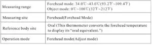
Measuring range:Forehead mode ‘ 90°F – 110″F (32.2″C – 43.3°C)
Object mode ‘ 32″F – 212″F (0″C -100°C)
Accuracy:Forehead mode 90°F-110°F (32.2″C ~43.3″C) ‘± 0.4°F (0.2″C)
Object mode 32°F-212°F (0°C-100°C)’ ± 1.8°F (1 .0″C)
Resolution: 0.1°F(0.1°C)
Memory Sets: 10sets
Operating Condition: 60.8°F – 104°F(16°C – 40″C), 15 – 95%RH (non-condensing)
Storage Condition: -4°F-131°F (-20°C- 50″C), 15-95%RH (non-condensing)
Battery:AAA battery x 2
Battery Life:5000 measurements at least
Auto Power Off:After 60 seconds of inactivity
Dimension: 5.43×3.54×1 .77 inch (138 x 90 x 45 mm)
Weight: 132g including batteries
Certification: ISO 13485/ASTM E1965-98
ABOUT BODY TEMPERATURE
A person’s normal body temperature can range from 95.9°F to 100.0°F(35.5°C to 37.8°C) throughout the day. We recommend taking your temperature at different times during the day when you are NOT sick. This will give you a preliminary reference to know what your normal temperature is and how it fluctuated during a normal day. Then, when you feel sick or discomfort, knowing this will provide an index for a reliable diagnosis of a fever.
EXPLANATION OF SYMBOLS

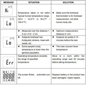
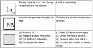
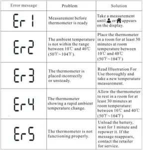
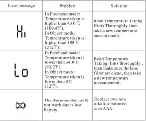
TROUBLESHOOTING

The reading is over measuring range.
Please wait a few minutes and measure again.

The ambient temperature is out of the Operation Environment range.
The device self-diagnostic is failed. Please contact the distributor.
BATTERY INSTALLMENT
- Replace with 2 new AAA batteries simultaneously when <1) ® <ID the low battery indication appears.
- The memories might be erased after replacing the battery.
- Remove battery if the device is not likely to be used for a long period of time.
- Do not dispose the battery in a fire, the battery will explode.
Replace Battery
- Remove the battery cover to insert battery.
- Confirm the polarity (+ and -) of batteries are correct as • ~ indicated inside the compartment and insert batteries accordingly.
- Replace the battery cover.
WARNING
- Discard old battery carefully, out of reach of young children. Swallowing the battery may be fatal. If the battery is swallowed, contact a hospital immediately to have it removed. Do not dispose of the battery in a fire. It may explode.
- For battery disposition, please consider the national regulation
CLEANING AND DISINFECTION
- To clean and disinfect the device, use a cotton swab or pad moistened with 70% alcohol to wipe the probe.
- Use a cloth dampened with water or neutral detergent to clean and dry the device.
- Do not use thinner, benzene, and other harsh cleaners for cleaning the device.
- Do not immerse the unit in water or liquid of any kind. The unit is not water proof.
. Do not submerse or expose the device to water.
, Do not use corrosive detergent to clean the device. Clean and disinfect the thermometer before and after use.
Drying process
- After cleaning and disinfection process,
- Put the device to air-dry in the room temperature 68-86°F(20-30°C), exposure time around 30-60 min.
- And store the device in a dry, clean, and dust-free environment at moderate temperatures of 41 °F(5°C) to 104°F(40°C).
CARE AND STORAGE
- Do not drop or crush the device. It is not shock proof.
- Do not dismantle or modify the device other than changing the batteries.
- Do not store the device in an extreme environment with direct sunlight, high/low temperatures or in a location with high humidity or severe dust.
Please contact your local agents or distributors if the device does not function properly as specified under PRODUCT SPECIFICATION.
SAFETY INSTRUCTIONS
WARNING:
- Read the entire instruction manual before trying to operate the device.
- The device is delivered non-sterile; please clean the device before measuring.
- Stop using the device if malfunctions appear or if it operates abnormally.
- Children should not use the device without the supervision of an adult. Keep out of reach of unsupervised children.
- Do not use the device when flammable materials are around.
- Do not place the device on scarred tissue, open wounds or abrasions.
- Some medications may cause a rise in skin temperature which can consequently lead to incorrect measurements.
- Taking a measurement after skin has been exposed to an extreme condition such as direct exposure to sunlight, fireplace/ heater or air conditioner flow, may lead to incorrect readings.
- If the device has been kept or stored in extreme temperatures, wait at least one hour for the device to return to room temperature before measuring.
- Do not touch the probe, unless the device is on the measuring.
- The device is not water resistance, please keep dry.
- Do not drop the thermometer or expose it to heavy shock.
- Do not bite or swallow the probe and the battery cover.
- Do not let thermometer come into contact with any thinner or chemical solvents.
- Components may be harmful ff swallowed. Contact a physician immediately should this occur.
- Do not use it if the display malfunctions or it operates irregularly.
- Do not put this unit in dishwasher.
- Performance of the thermometer may be degraded if: Operated or stored outside stated temperature and humidity ranges or if the patient’s temperature is below the ambient (room) temperature.
- The reading is for reference, iffeel sick or uncomfortable, please contact the physician.
CAUTIONS:
- Do not scrape or scratch the probe as it will hamper the effectiveness of the device.
- Do not dismantle the device except when replacing the battery.
- Wait at least thirty minutes after exercising, bathing or eating before taking a measurement.
- If the subject’s body temperature is lower than the room temperature, a false reading may occur.
- To ensure the best performance of the device, please follow the Product Specification “Storage condition” regarding temperature and humidity ranges for storing the device.
- Dispose of the device and battery according to your local regulatory or environmental protection agency
- The device is not intended for use in the emergency medical services environment.
WARRANTY INFORMATION
Warranty:
The device itself (battery excluded) comes with one year warranty from purchasing date if it is operated under normal circumstances without evidence of tampering. See exclusions below.
Warranty exclusions:
- If user does not properly operate the device according to the instructions as described in this manual.
- If the device shows signs of tampering or attempted modification.
- Improper handling, such as dropping, liquid or cleaner damage.
- Natural disasters (such as fire, flood, earthquake, thunder strike).
- If you do not have a receipt or proof of purchase showing date of purchase
Infrared Thermometer KI-8280 Instruction Manual Original-PDF
Infrared Thermometer KI-8280 Instruction Manual Optimized-PDF
References