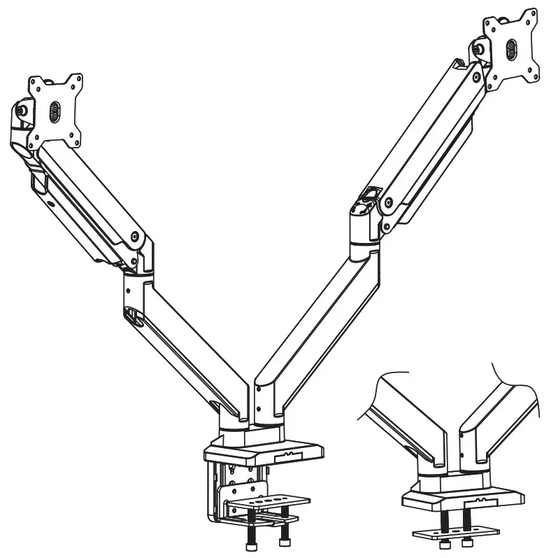
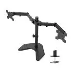
Dual Monitor Desk Mount

WARNING!
If you do not understand these directions, or if you have any doubts about the safety of the installation, please call a qualified technician. Check carefully to make sure there are no missing or defective parts. Improper installation may cause damage or serious injury. Do not use this product for any purpose that is not explicitly specified in this manual. Do not exceed weight capacity. We cannot be liable for damage or injury caused by an improper mounting, incorrect assembly or inappropriate use.
TIPOVER WARNING
SERIOUS OR FATAL CRUSHING INJURIES CAN OCCUR FROM TIPOVER. TO HELP PREVENT TIPOVER:
- NEVER ALLOW CHILDREN TO CLIMB, STAND, HANG, OR PLAY ON ANY PART OF THE MONITOR OR STAND.
- USE TIP-OVER RESTRAINT OR ANCHOR STAND TO WALL.
USE OF TIP-OVER RESTRAINTS MAY ONLY REDUCE, BUT NOT ELIMINATE THE RISK OF TIP-OVER.
SMALL PARTS- NOT FOR CHILDREN UNDER 3 YEARS. ADULT SUPERVISION IS REQUIRED.
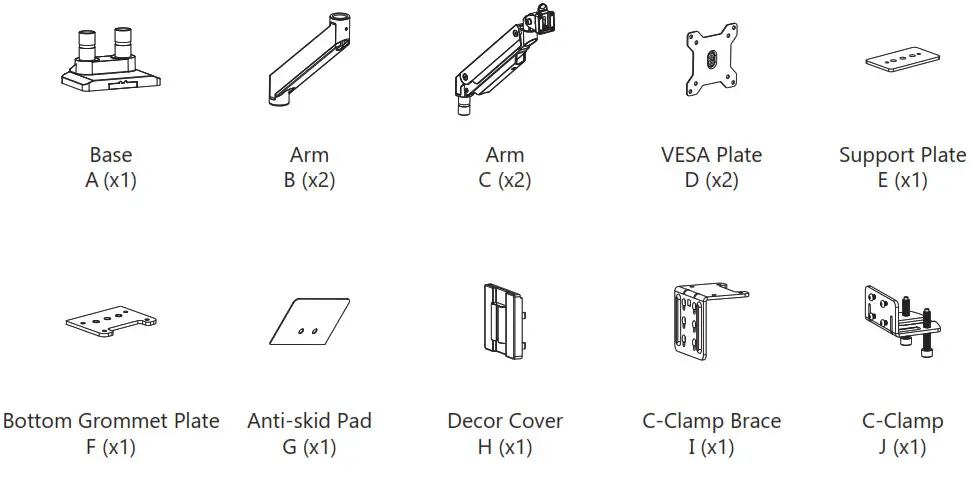
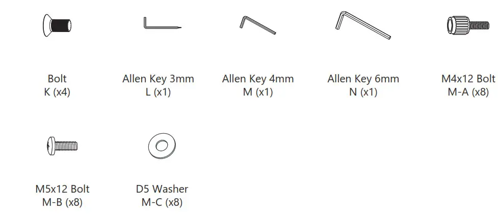
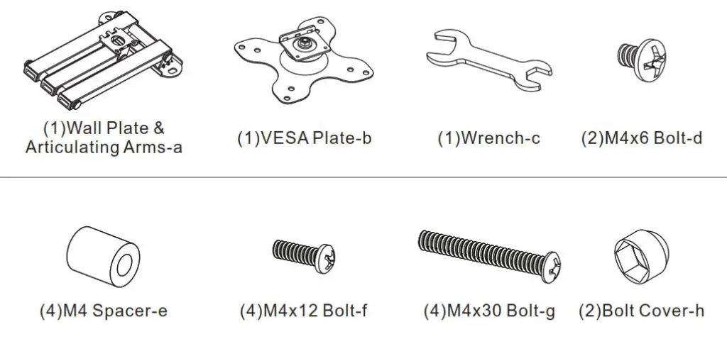
Supplied Parts List

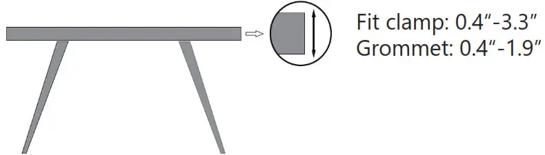
Step 1
Measure the thickness of your mounting surface or desk.
Step 2
Option A Clamp Installation
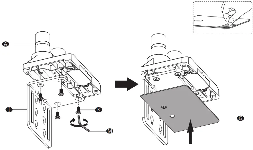
- Connect the C-Clamp Brace I to the Base A from the bottom using 4 pcs Bolt K and tighten with Allen Key 4mm M . Tear off the protective paper to attach Anti-Skid Pad G to the bottom designated position of Base A as the image shown.
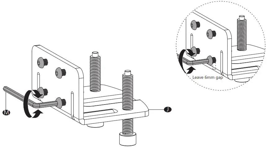
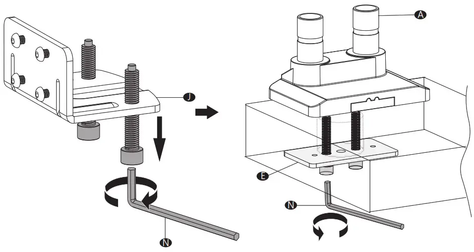
- Loosen the Bolts on the C-Clamp J using Allen Key 4mm M.
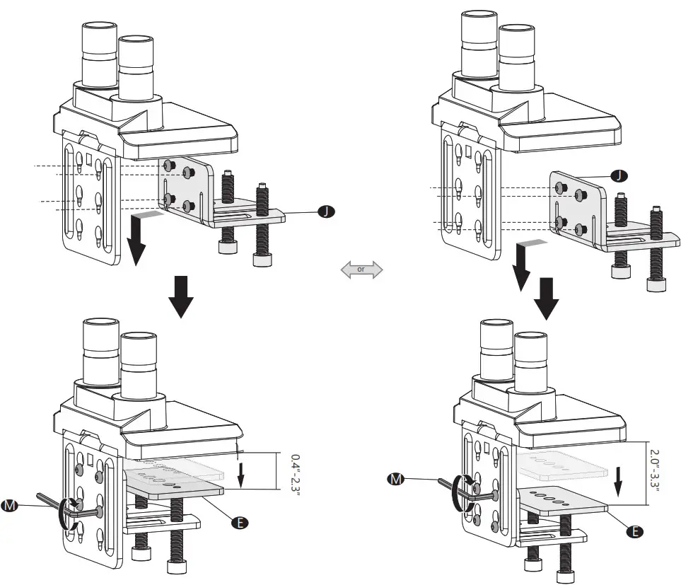
- Hang the C-Clamp J on the C-Clamp Brace I to the preferred height according to your desk thickness and tighten using Allen Key 4mm M . Place Support Plate E on top of clamp bolts.
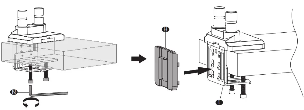
- Position base on desktop and tighten clamp bolts evenly using Allen Key 6mm N . Attach Decor Cover H to back of C-Clamp Brace I.
Step 2
Option B Grommet Base Installation
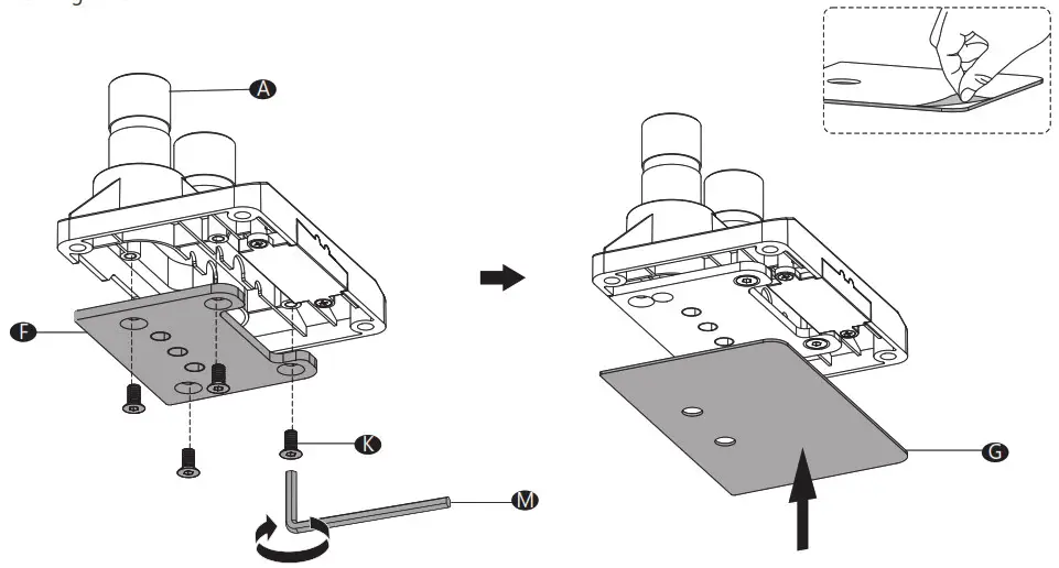
- Connect the Bottom Grommet Plate F to the Base A from the bottom using 4 pcs Bolt K and tighten with Allen Key 4mm M . Tear off the protective paper to attach Anti-Skid Pad G to the bottom designated position of Base A as the image is shown.
- Remove clamp bolt from C-Clamp J using Allen Key 6mm N. Place the Base A onto the desk hole, and guide the Support Plate E through the bolt. Tighten the bolt to the base for stability using Allen Key 6mm N.
Step 3
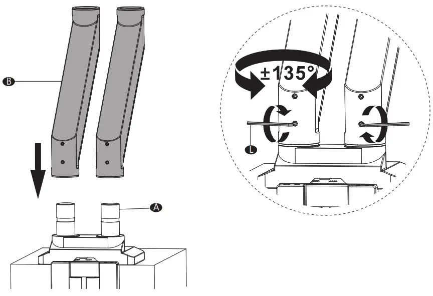
Connect the Arm B to Base A and tighten the lower screw with Allen Key 3mm L.
 Step 4
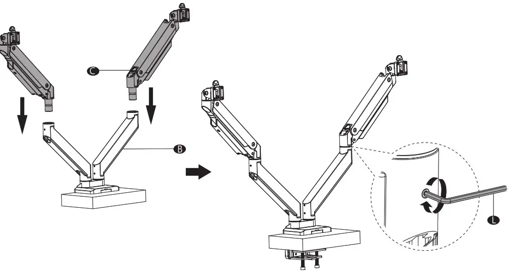
Connect Arm C to Arm B and tighten with Allen Key 3mm L.
Step 5
Step 5.1
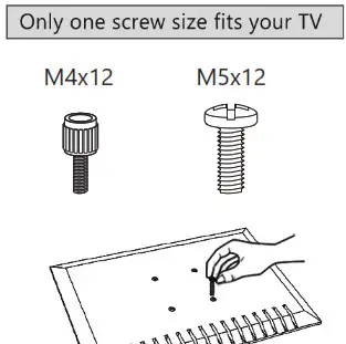
 Hand thread screws into the threaded inserts on the back of your TV to determine which screw diameter (M4) or (M5) to use.
Step 5.2
Select M4x12 Bolt M-A or M5x12 Bolt M-B according to your TV/Monitor, connect VESA Plate D together with D5 Washer M-C into the mounting holes on the back of TV/Monitor, tighten with a screwdriver. (Screwdriver needed but not included)
 Step 6
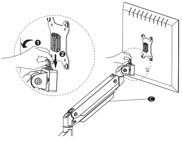
Pull the buckle and put the assembled TV/Monitor onto the Arm C and ensure stability.
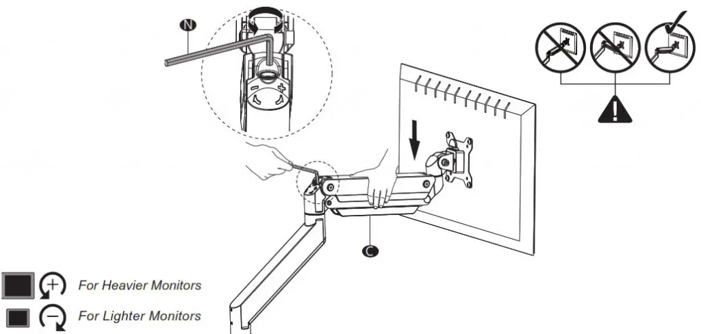
 Step 7
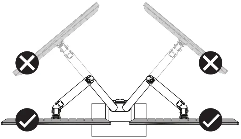
Press the Arm C on the horizontal level as the image shown, adjust gas spring tension to your personal preference using Allen Key 6mm N.
Adjust the Gas Spring Tension
- Insert the 6mm Allen Key into the adjusting hole and turn clockwise (-) to reduce gas spring tension, suitable for lighter screens.
- Insert the 6mm Allen Key into the adjusting hole and turn counter-clockwise (+) to increase gas spring tension, suitable for heavier screens.
- Please take note it may take numerous turns for gas spring tension adjustment.
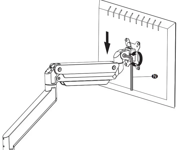
 Step 8
Adjust the tilt tension using Allen Key 6mm N.
Step 9
Screw out the bolts and take off the cable cases.
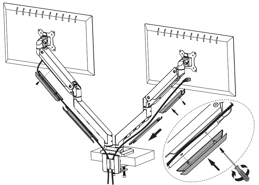
Step 10
Guide the cables through and put the cable cases back.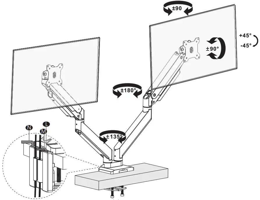
Step 11
For safety, please do not extend the monitor behind the desk. This may cause instability and tip the desk over.
Step 12
Manually swivel, tilt, and rotate the monitor for the best viewing angle. Store the Allen Keys in the holder of Decor Cover H for future convenience. 
![]()
Thank you for choosing us!
We support the technology that brings your home to life.
We offer high-quality products, professional customer service,
and extensive technical support.
If you have any questions, please contact us.
 1-844-SATTLER (18447288537)
 [email protected]
 www.walielectric.com
INSTALLATION MANUAL
1330LM
[email protected]
UNPACKING INSTRUCTIONS
- Carefully open the carton, remove contents, and layout on cardboard or another protective surface to avoid damage.
- Check package contents against the Supplied Parts List on the next page to assure that all components were received undamaged. Do not use damaged or defective parts.
- Carefully read all instructions before attempting installation.
IMPORTANT SAFETY INFORMATION
Install and operate this device with care. Please read this instruction before beginning the installation, and carefully follow all instructions contained herein. Use proper safety equipment during installation. Please call a qualified installation contractor for help if you:
- If you don’t understand these directions or have any doubts about the safety of the installation.
- If you are uncertain about the nature of your wall, consult a qualified installation contractor.
Do not use this product for any purpose or in any configuration not explicitly specified in this instruction. We hereby disclaim any and all liability for injury or damage arising from incorrect assembly, incorrect mounting, or incorrect use of this product.
Supplied parts list

| CAUTION! | |
| This TV mount must be securely attached to the vertical wall. If the mount is not properly installed it may fall, resulting in possible injury and/or damage. |
Tools Required
- 4mm Drill bit.
- Phillips Screwdriver
- 10mm masonry bit.
- Carpenter’s Level.
Note: The mounting components and hardware supplied in this package are not designed for installations to walls with steel studs or to cinder block walls. If the hardware you need for your installation is not included, please consult your local hardware store for proper mounting hardware for the application.