
- This kit converts all 33/35A and 98/99 series EL devices and fire devices built prior to Oct. 2014 to quiet electric latch (QEL) retraction devices.
- QELX and HD-QELX Baseplate Conversion Kits are only for use with Von Duprin AX98/99, AXXP98/99, and AX33A/35A exit devices only.
They are not to be used to convert standard exit devices to QELX. - Install according to instructions or device will not function and panic or fire label will be void.
- The QEL wiring must be attached to the fire alarm system if installed on fire exit hardware.
Parts
Tools Required


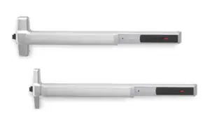
QEL Baseplate w/o Dogging (replaces EL Baseplate and Fire Baseplate)
QEL Baseplate with Dogging (replaces EL-HD Baseplate)
![]()
If existing exit device is fire rated, do not install HD-QEL or HD-QELX (hex dogging) baseplate. Doing so will void fire rating.
Setup Instruction

To avoid risk of shock, disconnect AC power from power supply before proceeding with this conversion. If using Battery Backup option, unplug all four wires from battery terminals.- Detach Vertical Rods if present Refer to device instructions as needed.
- Remove Exit Device from Door
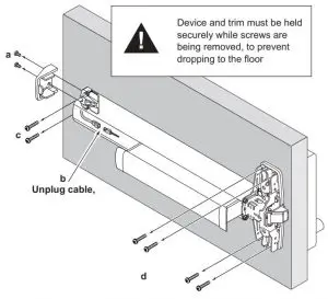
4. Remove Old Baseplate Assembly
4a Remove Mechanism Case
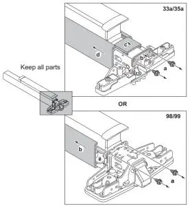
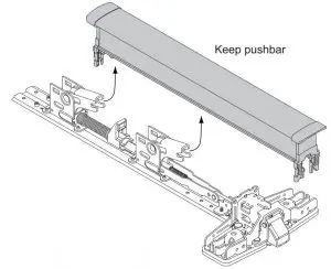
4b Remove Pushpad From Baseplate.
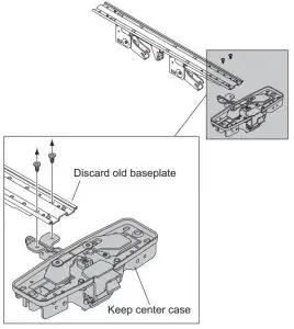
4c Discard retaining ring and pin

4d Discard old baseplate
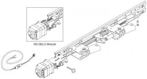
5. Install New QEL Baseplate Assembly
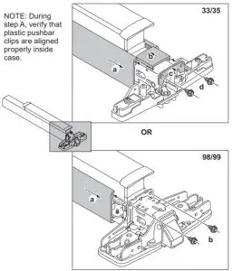
5a Attach existing center case to new baseplate using two screws
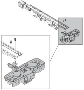
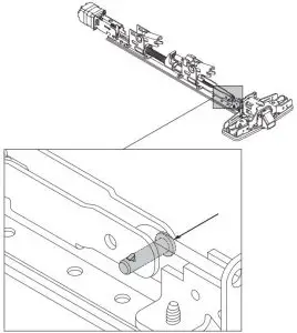
5b Install new slic pin
5c Install pushpad
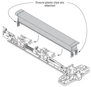
6. Install mechanism case
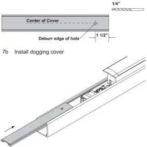
7. Prepare dogging cover for HD dogging key (if applicablle and only on panic devices).
7a Locate and drill hole
8. Drill Wire Access Hole (if required)

9. Attach Exit Device to Door

For more detailed installation instructions for specific Exit Devices, visit the Support area of the Allegion website at www.allegion.com/us
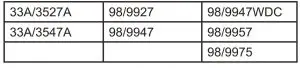
10. Confirm Equipment Compatibility
The QEL is compatible with the following equipment (refer to individual instructions as needed):
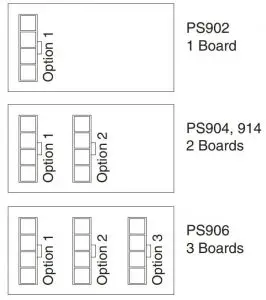
- PS900-SERIES POWER SUPPLIES – PS902, PS904, PS906, PS914
- 900-SERIES OPTION BOARDS – 900-2RS, 900-4R, 900-4RL, 900-2Q
- PS873 POWER SUPPLY PLUS 871-2, 871-2Q, 873-4TD/AO OPTION BOARDS
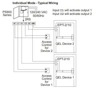
11. Route Two Wires from QEL Exit Device to Power Supply
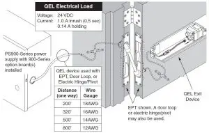
Note: Power wires to QEL are not polarized.
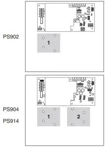
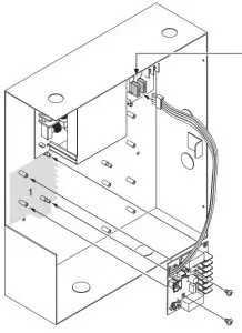
12. Install 900-2Rs, 4Rl, or 4R Option Board(s) into Power Supply
12a Review Available 900 series Option Board Mounting Locations (Gray)

12b Plug Option Board Cable into any Available Option Connector.
12c Secure Board(s) with Screws
Notes:
- 24VDC output setting required when QEL device connected
- 2. If installing board in location 2 or 3, rotate board 180°
- The QEL is compatible with an existing 900-2Q board if currently installed.
- Latchbolt retraction of (2) sequenced QEL’s requires more than 1 second to complete.
- When powering multiple components, verify that the amperage requirements of all components combined does not exceed the power supply output rating.
13. Connect Input and Output Wires to Option Board (2RS Shown)

14. Check Operation
- Activate each input and verify all QEL devices operate properly.
- If any device does not operate properly, see step 15 for troubleshooting.
15. If Necessary, Troubleshoot Operation (LED is only visible with the mechanism cover removed)
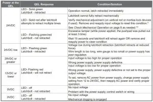
*For information about adjusting exit devices, you can find their installation instructions in the support area at www.allegion.com/us or call Technical Services at 1-877-671-7011

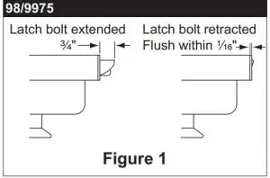
16. Check Mechanical Operation
- Make sure device is not dogged for SD-QEL / HD-QEL.
- Depress pushbar and make sure latch bolt retracts and extends fully (see Figure 1).
- If latch bolt does not retract or extend fully, adjustments may be required per the device installation instructions.

- Make sure device is not dogged for SD-QEL/HD-QEL.
- Depress pushbar. Door should begin to open with pushbar depressed halfway.
- Close door. Top latch should be secure. If two point latch, bottom latch should be secure as well.
- If device does not function as described in steps 2 and 3, adjustments may be required per the device installation instructions.
Any HD Device
- Fully depress pushbar.
- Insert hex dogging key and turn clockwise.
- Release pushbar and verify latchbolt remains retracted.
- Fully depress pushbar.
- Insert hex dogging key and turn counter clockwise.
- Release pushbar and verify latchbolt extends fully.
Customer Service
Call: 1-877-671-7011
Visit: www.allegion.com/us
![]()
© Allegion 2020
Printed in U.S.A.
24908394 Rev. 10/20-e