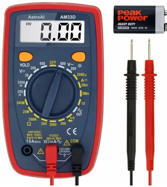
Thank you for purchasing the Digital Multimeter from AstroAl. The AstroAl Digital Multimeter is designed to be safely and accurately used in schools, laboratories, factories and other social/industrial fields. This user manual provides all the safety information, operation instruction, specifications, and maintenance for the meter. This instrument performs AC/DC Voltage, DC Current, Resistance, Diode Testing and Continuity Testing. Thank you again for choosing AstroAl, if you have any questions or concerns regarding your product, please contact us at [email protected].
NOTE:
Fully read and comprehend this manual before using this Digital Multimeter.
WARNING
To avoid possible electric shocks, personal injury and to avoid possible damage to the Meter or to the equipment being tested, adhere to the following rules:
- Use the Meter strictly in accordance with this manual, otherwise the protection function provided by the Meter may be damaged or weakened.
- Please be especially careful when measuring over 60V DC, 30V AC RMS or 42V peak value, there is a danger of electric shocks.
- Do not apply more than the rated voltage marked on the Meter, between the terminals or between any terminal and grounding.
- Check whether the Meter is working normally by measuring the known voltage, do not use it if the readings are incorrect or the Meter is damaged.
- Before using the meter, please check whether there are cracks or damage to the plastic parts of the meter casing. Do not use the Meter if all or part of the exterior casing is damaged.
- Before using the Meter, please check whether the test leads are cracked or damaged. Please replace the test leads with those of the same model and same electrical specifications if the leads are damaged.
- Use the Meter according to the measurement category, voltage or current rating specified on the meter or manual.
- Comply with local and national safety regulations. Wear personal protective equipment (such as approved rubber gloves, masks, and flame-retardant clothing, etc.) to prevent injury from electric shocks and arcs when hazardous live conductors are exposed.
- Replace the battery as soon as the low-battery indicator appears to avoid measurement errors.
- Do not use the Meter around explosive gas. steam or humid environ rne
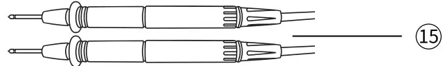
- vvhntens. using the test leads, keep your fingers behind the finger guards.
- When measuring, connect the neutral wire or ground wire first, then connect the live wire; when disconnecting. disconnect the live wire first, and then disconnect the neutral and ground wires.
- Before opening the case or battery cover, remove the test leads from the Meter first. Do not use the Meter when it is disassembled or when the battery cover is opened.
- The Meter can only be used with the equipped test leads to meet the requirements of safety standards If the test leads are damaged and need to be replaced, replace only with the same model and the same electrical specifications.
ELECTICAL SYBOLS
 |
AC (Alternating Current) |
 |
Low Battery Symbol |
 |
DC (Direct Current) |  |
Audible Continuity Test |
| V | Voltage |  |
Diode Test |
| A | Current |  |
Resistance Test |
 |
Square Wave |  |
Earth Ground |
 |
Double Insulation |  |
Warning |
 |
Compliant with EU Standards | ||
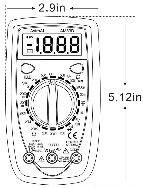
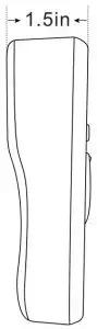
SIZE
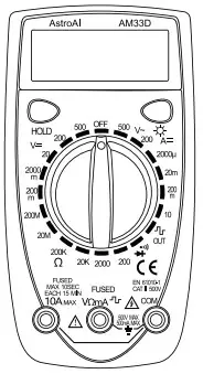
DIAGRAM
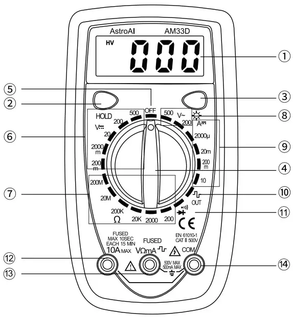
- LCD Screen
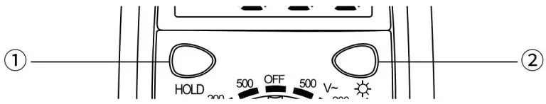
- Hold Button
- Backlight Button
- Rotary Switch
- OFF
- DC Voltage Test
- Resistance
- AC Voltage Test
- DC Current Test
- Square Wave Output
- Continuity Test/Diode Test
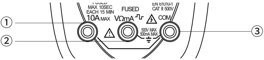
- 10A Termina
- vnwm Terminal
- Com Terminal
- Test Leads
GETTING TO KNOW YOUR DEVICE
BUTTON FUCNTIONS
 |
|
| BUTTONS | FUNCTIONS |
|
|
|
 |
|
|
|
|
|
| 3 |
|
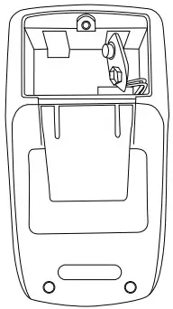
REPLACING THE BATTERY AND FUSE
- Turn off the Meter and remove the test leads.
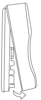
- Unscrew the screws (that fix the battery cover) with a screwdriver, and remove the battery cover.
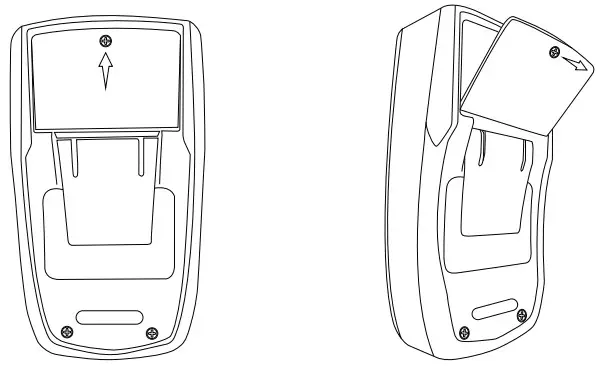
- Remove the old battery and replace it with a new battery of the same specification.
- Put the battery cover back to its original position and fix the battery cover with the removed screws.
Battery Type: 1 x 9V Battery NEDA 1604/6F22/006P
REPLACING FUSE
- Turn off the Meter and remove the test leads.
- Unscrew the screws fixing the battery cover with a screwdriver, and remove the battery cover and the battery
- Remove the insulating sleeve and screws on the back cover of the
Meter.
- Remove the blown fuses and replace them with new fuses of the
same specification, make sure that the fuses are loaded into the fuse
clip and clamped tightly.
- Put the insulation cover, the battery and the battery cover back, and lock the cover with screws.
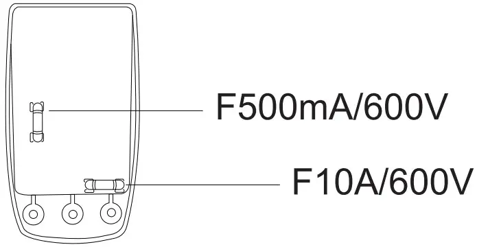
THE SPECIFICATIONS OF FUSES
- Fuse 1: F500mA/600V fuse; Size:p5*20mm
- Fuse 2: F10A/600V fuse; Size:p5“20mm
OPERATION INSTRUCTIONS
- To avoid damage to the Meter, do not measure voltages exceeding SOOV.
- This Meter is a manual range Multimeter. Please be sure to choose the correct measuring range to prevent damage.
- Pay special attention to safety when measuring high voltages to avoid electric shock or personal injury.
- Before using the Meter to test a known voltage or current, confirm that the Meter functions work properly.
MEASURING AC/DC VOLTAGE
MEASURING DC VOLTAGE
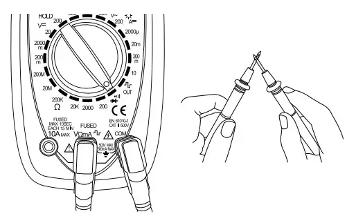
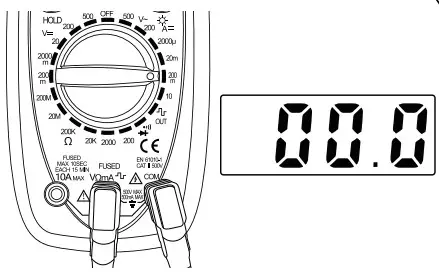
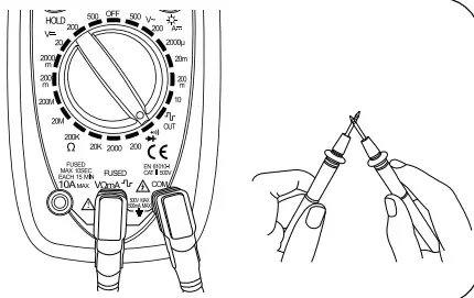
- Insert the red test lead into the “ vnmAm “terminal and the black test lead into the “COM” terminal.
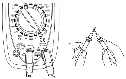
- Turn the rotary dial to the continuity test, touch the red test lead and the black test I ead to check whether they are normal. The buzzer will beep if the test leads are normal.
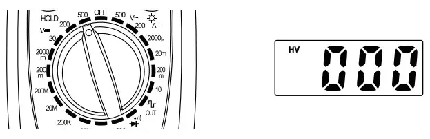
- Turn the rotary dial to the “ V- ” area with a white font. The screen will display “000” indicating that the measurement function is DC voltage.
NOTE
- Of The test unit of “v=” area is “V ”; If the number on the white area is followed by “m”, then the test unit is “mV”.
- If the measurement range is the maximum, that is, 500 V setting, “HV” will be displayed on the screen.
- Connect the test leads to the circuit under test (connect the leads in parallel to the power supply or circuit under test) to measure.
NOTE
- @ If the reading is negative when measuring the DC voltage, it means that the positive and negative poles of the test leads are reversed, please change the test leads.
- After the reading stabilizes, record the reading from the LCD screen.
- Turn the rotary switch to the OFF position to turn off the Meter.
MEASURING AC VOLTAGE
- Insert the red test lead into the “ VnmA -’tr” terminal and the black test lead into the “COM” terminal.
- Turn the rotary dial to the continuity test, touch the red test lead and the black test lead to check whether they are normal. The buzzer will beep if the test leads are normal.

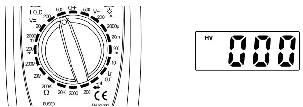
- Turn the rotary dial to the “V ” area with a white font. The screen will display “000” indicating that the measurement function is DC voltage.
NOTE
@ The test unit of “V ”area is “V”. 2 If the measurement range at the maximum (SOOV setting) “HV” will be displayed on the screen.
- Connect the test leads to the circuit under test (connect the leads in parallel to the power supply or circuit under test) to measure.
- After the reading stabilizes, record the reading from the LCD screen.
- Turn the rotary switch to the OFF position to turn off the Meter.
VOLTAGE TIPS
HOW TO FIND A LIVE WIRE IN A SOCKET
- Switch to the voltage test setting.
- Connect the black test lead to the grounded wire or jack. Connect the red test lead to one of the jacks to be measured.
- Check both jacks. One should have a reading and the other should remain at or near zero. The live wire will have the reading.
VOLTAGE NOTES
- Choose the SOOV setting to measure the unknown voltage first, and then select the appropriate range according to the voltage.
- To avoid damage to the meter, do not measure voltage exceeding SOOV DC or SOOV AC CATII.
- If the AC setting is used to measure DC and vice versa, an overflow symbol will be displayed. Performing this action has the potential to damage the Meter or any components you are attempting to test.
- When measuring voltage, the result will fluctuate depend ing on the power supply. Generally, the result will fluctuate +10V, which is NOT an inaccurate result.
MEASURING DC CURRENT
- Disconnect the power supply of the circuit under test.
- Insert the red test lead into the “ “ terminal and the black test lead into the “COM” terminal.
- Turn the rotary dial to the continuity test, touch the red test lead and the black test lead to check whether they are normal. The buzzer will beep if the test leads are normal.
- Insert the black test lead into the “COM” terminal and red test lead into the 10A terminal.
NOTE
@ Please be sure to start the test from the 10A setting when measuring the unknown current. - Turn the rotary dial to the 10A setting of “A=” area. The screen will display “000” indicating that the measurement function is a DC current from 200mA to 10A.
- Connect the Meter to the circuit under test in series, and then turn on the power supply of the circuit.
- After the reading stabilizes, record the reading from the LCD screen.
- Turn the rotary switch to the OFF position to turn off the Meter.
MEASURING DC A CURRENT
- Disconnect the power supply of the circuit under test.
- Insert the red test lead into the “VDmA-‘Tr” terminal and the black test lead into the “COM” terminal.
- Turn the rotary dial to the continuity test, touch the red and black test leads to check whether they are normal. The buzzer will e beep if the test leads are normal.

- Turn the rotary dial to the “A=” area with yellow font. The screen will display “000” indicating that the measurement function is a DC A current from 200pA to 200mA.
 NOTE
NOTE
@ The test unit of “ A= ”area is “A”; If the number on the yellow area is followed by “m™, then the test unit is “mA”. - Choose a larger setting to measure the unknown current first, and then select the appropriate range according to the current.
- Connect the Meter to the circuit under test in series, and then turn on the power supply of the circuit.
- After the reading stabilizes, record the reading from the LCD screen.
- Turn the rotary switch to the OFF position to turn off the Meter
AUTOMOTIVE PARASITIC BATTERY DRAIN
- Check if the battery voltage and power generation are within normal range. The battery voltage is generally around 12.7V and the power generation is around 14V.
- Turn off all electrical accessories inside and outside the car and close the doors.
- Remove the negative electrode of the battery. Set the Multimeter to the maximum current level and connect the Meter in series to the battery.
Connect the red test lead to the negative line and the black test lead to the battery terminal. - Adjust the Meter, if necessary, to a lower range.
- Wait for about 30 minutes; after all the modules of the vehicle have entered the sleep state, read the accurate static discharge current. The discharge current is generally 0.02A (20mA), however, this can vary depending on the vehicle. Normally it will not exceed 50mA.
- If the drain is larger than 50mA, begin checking fuses individually for which circuit is carrying the excess load.
If a removed fuse reduces the battery draw to below 50mA, it can be determined that the corresponding circuit is drawing the excess discharge.
CURRENT NOTES
- Choose the maximum setting to measure the unknown current first, and then select the appropriate range according to the current.
- If you insert the red test lead into the 10A jack, be sure to insert the test lead back into the “ VnmAm ” jack after the test to avoid forgetting to switch the jack for the next operation and thus burning the Multimeter.
- When testing a high current, for safety reasons, each measurement time should be less than 10 seconds, and the interval time between tests should be greater than 15 minutes.
- When testing the current, there must be a load in the circuit. Do not connect the multimeter in series with the circuit without a load to measure; doing so can potentially damage the Meter.
- Do not apply a current exceeding the Meter’s range to avoid damaging the Meter.
MEASURING RESISTANCE
- Insert the red test lead into the “VnrnA-’Ir” terminal and the black test lead into the “COM” terminal.
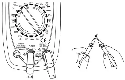
- Turn the rotary dial to the continuity test, touch the red and the black test leads to check whether they are normal. The buzzer e will beep if the test leads are normal.
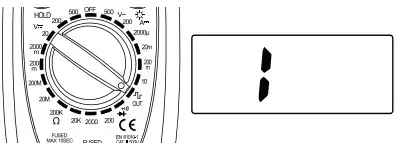
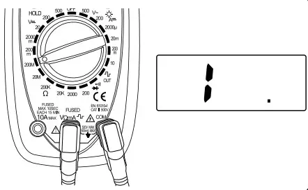
- Turn the rotary dial to the“CI” area with a yellow font. The screen will display “1” indicating that the measurement function is resistance.

NOTE
- The test unit of “Cl” area is “Cl”; If the number on the yellow area is followed by a“M”, then the test unit is “MD”; If the number on the yellow area is followed by a “K”, then the test unit is “KPI”.
- Choose a larger measurement range to measure the unknown resistance first, then select the appropriate range according to the resistance.
- Connect the test leads to both ends of the circuit or resistor under test (connect the leads to the resistance under test in parallel).
- After the reading stabilizes, record it from the LCD screen.
- Turn the rotary switch to the OFF position to turn off the Meter.
RESISTANCE NOTES
- Do not change the resistance while taking a measurement.
Doing so may damage the Meter and affect the test results. - Do not test parallel circuits. The accuracy of the measurement will be affected, and the results may not be accurate.
- Do not directly measure the internal resistance of micrometers, galvanometers, batteries, and other instruments.
CONTINUITY TEST
- Insert the red test lead into the “VnmAT” terminal and the black test lead into the “COM” terminal.
- Turn the rotary dial to the “ ++ ”setting. touch the red and the black test leads to check whether they are normal. The buzzer will beep if the test leads are normal.

- Connect the test leads to both ends of the circuit or resistor under test (parallel). If the resistance of the circuit or resistor under test is connected and less than SOA, the buzzer will emit a beep sound.
- If the circuit or resistor under test is disconnected, or the resistance value is greater than 50Cl, the LCD screen will display “1”.

- Turn the rotary switch to the OFF position to turn off the Meter.
DIODE TEST
- Insert the red test lead into the “VCtmAm” terminal and the black test lead into the “COM” terminal.
- Turn the rotary dial to the “ ++’ ” setting. touch the red and the black test leads to check whether they are normal. The buzzer will beep if the test leads are normal.
- Connect the red test lead to the anode of the diode under test and the black test lead to the cathode of the diode.
NOTE
Usually the anode of the diode is the longer end. - The LCD screen will display the approximate voltage drop reading of the diode. The test unit is “mV”. If the test leads are connected in reverse, “1” will be displayed on the LCD screen.
Please replace the test leads to measure again. - Turn the rotary switch to the OFF position to turn off the Meter.
DIODE TEST TIPS
- Is the diode functioning correctly: If the red test lead is connected to the positive pole of the diode and the black lead is connected to negative, then the diode should be in a forward conduction state, and the displayed value is the forward voltage drop.
- Normal diode forward pressure drop: the general silicon tube is 0.5- 0.7 V, germanium tube is 0.15-0.3V.
- You can also verify that the red test lead is connected to the negative pole of the tested diode and the black test rod is connected to the positive pole. The diode should display“1″.
POLARITY JUDGMENT METHOD
- Switch the Multimeter to the Resistance setting.
- Connect the two test leads to the two electrodes of the diode.
- Measure one result, then swap the positions of the test leads and measure the second result.
- The larger result is the reverse resistance and the smaller result is the forward resistance. The smaller resistance is when the black test lead is connected to the positive end of the diode and the red lead is connected to the negative end.
SQUARE WAVE OUTPUT
- Insert the red test lead into the “VrznA-‘Tr” terminal and the black test lead into the “COM” terminal.
- Turn the rotary dial to the continuity test, touch the red test lead and the black test lead to check whether they are normal. The buzzer will beep if the test leads are normal.
- Turn the rotary dial to the “ ” setting. The screen will display “1” indicating that the measurement function is square wave output.
- Connect the test leads in parallel to both ends of the tested power supply or circuit.
- After the reading stabilizes, record the reading from the LCD screen.
- Turn the rotary switch to the OFF position to turn off the Meter.
MAINTENANCE
CLEANING THE METER
If there is dust or humidity in the terminals, it may produce erroneous measurements. Please clean the Meter as follows:
- Turn off the power to the Meter and remove the test leads.
- Turn the meter over and shake out the dust accumulated in the input jack, wipe the case with a damp cloth or mild detergent. Wipe the contacts in each terminal with a clean cotton swab dampened in alcohol.
SPECIFICATIONS
Accuracy is guaranteed for 1 year, with storage conditions of 23°C+5°C, less than 80%RH
| Digital Display | 2000, 3 / |
| Sampling Speed | 2 Times/Second |
| LCD Dimensions | 49 x 17mm |
| Range Selection | Manual |
| Polarity Indication | “-” Automatically Displayed |
| Overload Indication | “1” Displayed |
| Low Battery Indication | “ ”displayed when battery voltage is lower than normal |
| Work Environment | 32-104 °F; 0-40 °C, at <80%RH |
| Storage Temperature | 14-122 °F; -10-50 °C, at <85%RH |
| Power | 1 x 9V Battery NEDA 1604/6F22/006P |
| Weight | Approximately 145g |
| Dimensions | 130 x 73 x 37mm |
DETAILED SPECIFICATIONS
Accuracy is guaranteed for 1 year, with storage conditions of 23°C+5°C, less than 80%RH
- DC VOLTAGE
Range Resolution Accuracy Overload Protection 200mV 100pV * (0.5%+3) 220V RMS AC 2000mV 1mV 1 (0.8%+2) SOOV DC / SOOV RMS 20V 10mV 200V 100mV SOOV 1V * (0.8%*3) - AC VOLTAGE
Range Resolution Accuracy Overload Protection 200V 100mV *(2.0%+10) SOOV DC / SOOV RMS SOOV 1V - DC CURRENT
Range Resolution Accuracy Overload Protection 2000pA 1pA * (2.0%+5) 500mA, 600V fuse 20mA 10pA 200mA 100pA 10A 10mA * (2.5%+5) 10A, 600V fuse Measured Voltage Drop: 200mV
- RESISTANCE
Range Resolution Accuracy Overload Protection 200CI 0.1CI (1.5%*5) 15 seconds maximum exposure to 220Vrms 2000CI 1CI * (1.0%*4) 20KCt 10CI 200KCI 100D 20MCI 10KCI -L (1.0%+10) 200MCI 100KCI -L (1.0%+10) Maximum Open Circuit Voltage: 3V
- CONTINUITY TEST
Range Resolution Overload Protection 
Built-in buzzer sounds if resistance is less than 301-20CI 15 second maximum exposure to 220V RMS
INCLUDED IN BOX
- 1 x User Manual
- 1 x Pair of Test Leads
- 1 x AstroAl Digital Multimeter
1 YEAR LIMITED WARRANTY FROM ASTROAI
Each AstroAl Digital Multimeter will be free from defects in material and workmanship. This warranty does not cover fuses, disposable batteries and damage from neglect, misuse, contamination, alteration, accident, or abnormal conditions of operation or handling, including over-voltage failures caused by use outside the Meter’s specified rating, or normal wear and tear of mechanical components. This warranty covers the original purchaser only and is not transferable. If this product is defective, please contact AstroAl Customer Support at [email protected].
Web: www.astoai.com
E-mail: [email protected]
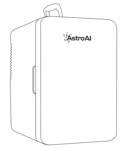
AstroAI 10L Mini Fridge
This manual contains important information regarding the safety, operation, maintenance, and storage of this product. Before using, read and understand all warnings, instructions and product labels. Failure to do so
could result in possibly injury or property damage. Please keep this manual for future reference.
Thank you for purchasing the AstroAI 10L Compact Portable Mini Fridge. This is a portable fridge that can be used with both a 12-volt car and a standard wall outlet. With an included chill and heat function, you’ll be able to keep everything at the perfect temperature.
We hope you enjoy your new Mini Refrigerator! Questions or Concerns? You are welcome to contact us with your question via [email protected].
SAFETY INFORMATION
- This appliance can be connected to a 110V supply by means of a threepin socket. (Countries with different voltages need to select products with corresponding voltages.)
- When using the 12V in-car adapter, the compact fridge should not be left connected for long periods of time when the engine is not running.
- DO NOT connect directly to a 24V lighter socket on a heavy-duty vehicle.
- Unplug this device during lightning storms or when not in use for long periods of time to prevent damage.
- DO NOT open or remove covers, doing so may expose you to dangerous voltages or other hazards.
- To prevent the risk of fire or electric shock, avoid overloading wall outlets, extension cords, or other devices that carry an electrical load.
- Only use suitable power sources – Plug the product into a suitable power source, as described in the operating instructions or as marked on the product.
- The supply voltage should be the same as that indicated in the technical specifications and the appliance rating plate.
- In order to disconnect the device from the mains completely switch off the outlet and remove the mains plug.
- Do not bend, stretch or pull the supply cable in order to avoid electric shock.
- When installed, the power socket must be within easy reach.
- Avoid using locations where dust or other airborne contamination may be drawn into the fan.
- Allow at least 2 inches of distance from the back and sides of the device to allow proper air circulation and heat dispersal.
- Never leave the fridge running in poorly ventilated areas e.g. a car’s trunk.
- Handle with ease and do not squeeze.
- Do not sit on the fridge.
- Allow 30 minutes for the compact fridge to return to room temperature before attempting to switch from heating to cooling mode, or vice versa.
- Do not expose the fridge to rain and keep the fridge away from corrosive gases and liquids.
- Disconnect the power supply when not in use for an extended period of time. Store in a cool, dry, and well-ventilated environment. Avoid exposing the device to direct sunlight.
- Not for children. This device should be used with adult supervision.
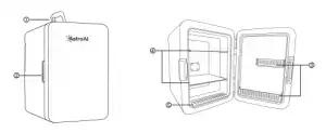
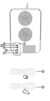
DIAGRAM

- Carrying Handle
- Door Handle
- Removable Shelf
- Condensation Water Tank
- Red Indicator Light
- Green Indicator Light
- Warm/Off/Cool Switch
- Non-ECO/ECO
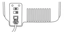
- DC Power Port
- AC Power Port
- AC Cord and plug
- DC Cord and plug
- Shelf
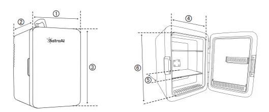
SIZE DESCRIPTION
- 25cm—9.8in
- 32.5cm—12.8in
- 35.2cm—13.9in
- 19cm—7.5in
- 18cm— 7.1in
- 27cm—10.6in
INSTRUCTIONS
CONNECTING TO 12V CIGARETTE LIGHTER
- Set the MODE switch to the OFF position before connecting to the 12V outlet. The two indicator lights will be off.
- Insert the DC power cord into the DC power port at the rear of the fridge.
- Secure the fridge in place and insert the power cord into the 12V socket

- Turn the MODE switch to either WARM or COOL. The green indicator light will be on under the COOL mode, and the red indicator light under the WARM mode.
WARNING: Running the portable fridge while your vehicle is off may drain the vehicle’s battery.
CONNECTING TO A WALL OUTLET
- Set the MODE switch to the OFF position before connecting to the wall outlet. The two indicator lights will be off.
- Insert the AC power cable into the AC power port at the rear of the fridge
- Secure the fridge in place and insert the power cable into the wall outlet.
- Turn the MODE switch to either WARM or COOL. The green indicator light will be on under the COOL mode, and the red indicator light under the WARM mode.
TIPS FOR MODES
ECO MODE
- ENERGY SAVING MODE. The lowest cooling temperature in this mode is higher than that in the non-ECO mode, the cooling rate is slower than that in the non-ECO mode, and the noise is much lower than that in the non-ECO mode.
- The fridge will default to a mode. If the noise is too loud, you can switch from non-ECO mode to ECO mode; If you are not satisfied with the cooling operation,you can switch from ECO mode to non-ECO mode.
COOLING TIPS - To achieve the quickest cooling, fill the fridge with beverages which have already been refrigerated.
- The lowest possible temperature depends on the ambient environment. The lowest temperature the fridge can achieve may rise if the ambient temperature is too high.
NOTE: Ambient temperature refers to the temperature of the surrounding air. For example, if the fridge is used for cooling, and your immediate surroundings are 75°F(24°C),then the fridge will have a difference of
3- 8°F (1.7-4.4°C)based on the temperature you set.
WARMING TIPS
- The fridge is designed to keep items warm. It is not designed to heat up cold items.
- Hot items will stay warm for several hours after the portable fridge has been turned off, provided that the door is closed properly.
CARE AND MAINTENANCE
- Ensure you disconnect the plug fully before performing regular maintenance.
- Clean the case with a damp cloth and mild cleaner.
- Ensure the inside is completely dry, when not in use, before storing.
TROUBLESHOOTING
| Does not work |
|
| Does not cool |
|
| Condensate water |
|
| Poor heat dissipation |
|
| Capacity | 10L | |
| Input voltage | DC 12V | cool mode: 4.2A |
| warm mode: 3.2A | ||
| AC 100-120V | cool mode: 0.85A | |
| warm mode: 0.7A | ||
| Operating temperature | Ambient Temp – 20°C Chill | |
| 140°F (60°C) Heat | ||
| Certifications | ETL , PSE , CE | |
3 YEAR LIMITED WARRANTY FROM ASTROAI
Each AstroAI 10L Mini Fridge will be free from defects in material and workmanship. This warranty does not cover damage from neglect, misuse, contamination, alteration, accident, or abnormal conditions of operation or handling. This warranty covers the original purchaser only and is not transferable. AstroAI always wants to provide our customers with excellent products as well as customer service. To know more about us, please visit astroai.com.
]]>