Model: PSE90
SAFETY DISCLAIMER
IMPORTANT SAFETY INSTRUCTIONS BELOW
WARNING: Failure to provide adequate structural strengthening, prior to installation can result in serious personal injury or damage to the equipment. It is the installer’s responsibility to ensure the structure to which the component is affixed can support four times the weight of the component and any additional apparatus mounted to the component.
WARNING: Do not exceed the weight capacity for this product as listed below. This can result in serious personal injury or damage to the equipment. It is the installer’s responsibility to ensure that the total combined weight of all attached components does not exceed that of the maximum figure stated.
WARNING: Risk of death or serious injury may occur when children climb on audio and/or video equipment or furniture. A remote control or toys placed on the furnishing may encourage a child to climb on the furnishing and as a result the furnishing may tip over on to the child.
WARNING: Risk of death or serious injury may occur. Relocating audio and/or video equipment to furniture not specifically designed to support audio and/or video equipment may result in death or serious injury due to the furnishing collapsing or over turning onto a child or adult.
WARNING – RISK OF INJURY!
Only for use with equipment weighing 132LBS (59KG) OR LESS.
Use with heavier projectors/equipment may lead to instability causing tip over or failure resulting in death or serious injury.
Bracket Suitable for Residential and Commercial Use.
ADDITIONAL WARNINGS:
- Keep all documentation/instructions after fitting.
- Read all technical instructions fully before installation and use. It is the installer’s responsibility to ensure that all documentation is passed on to the end user and read fully before operation.
- Do not use near water or outdoors unless the product has been specifically designed to do so.
- Protect any cables or cords being used near this bracket from being walked on or pinched to prevent damage and risk of injury.
- Use this product only for its intended purpose as described in the product instructions and only use attachments/ accessories specified by the manufacturer.
- Do not operate the product if it is damaged in any way, liquid has been spilled or objects have fallen into the
apparatus, the apparatus has been exposed to rain or moisture, does not operate normally, or has been dropped. Contact the original installer/manufacturer to arrange repair or return.
WARNING – To reduce the risk of burns, fire, electric shock, or injury to persons:
1. Clean only with a dry cloth and always unplug any electrical items being used in conjunction with this product before cleaning.
Future Sound & Vision trading as Future Automation intend to make this and all documentation as accurate as possible. However, Future Automation makes no claim that the information contained herein covers all details, conditions or variations, nor does it provide for every possible contingency in connection with the installation or use of this product. The information contained in this document is subject to change without prior notice or obligation of any kind. Future Automation makes no representation of warranty, expressed or implied, regarding the information contained herein. Future Automation assumes no responsibility for accuracy, completeness or sufficiency of the information contained in this document.
PRODUCT WARRANTY & RISK ASSESSMENT
WARRANTY INFORMATION
WARNING – The warranty offered for this product shall be annulled if the product is used improperly or in a way that is in breach of our Terms of Service.
Future Automation provides warranty for the mechanism you purchased for the period of 24 months from the date of purchase, provided that it isn’t used for unintended purposes.
Under the warranty, Future Automation aims to either solve the issue remotely (via telephone or email support) or if the mechanism requires a part, arrange a visit to your premises by a Future Automation approved engineer or send replacement items where appropriate.
Warranty repairs will be carried out as quickly as possible, but subject to parts availability. This warranty period is
respectively extended for the period of a repair.
A malfunctioning product must be cleaned and placed into suitable packaging to protect against transit damage before organising delivery to a repair workshop.
All the complaints about defects must be submitted to the vendor/installer that sold this product, rather than directly to the manufacturer.
Any part of your system that needs to be replaced during a warranty repair becomes the property of Future Automation.
The warranty does not cover the following:
- Damages resulting from improper product use or maintenance.
- Repairs carried out by unauthorized persons.
- Natural wear and tear during operation.
- Damages caused by the buyer.
- Accidental damages caused by a customer or damages caused as a result of careless attitude or usage, or damages caused by natural disasters (natural phenomena).
- Any electrical, or other environmental work external to your Future Automation mechanism including power cuts, surges etc.
- Additional items not supplied by Future Automation although they may have been supplied together by the retailer
- Any 3rd party software products controlling your mechanism
- Any transfer of ownership. Warranty is provided only to the initial purchaser.
- Compensation for loss of use of the product, and consequential loss of any kind.
A separate Safety and Servicing Information document is provided with these instructions (additional copies can be found at www.futureautomation.co.uk/safety), and this document MUST be filled out by the approved Future Automation Dealer who is installing the product. This Warranty Sheet must be held by the end user for the duration of the products life and will be referred to during servicing or warranty queries.
The Safety and Servicing Information document also contains two Service History Forms that must be filled in by the approved Future Automation dealer who is performing the first required yearly service of this product.
One copy of the Service History Form must be held by the customer (along with the Warranty Sheet) and a
duplicate copy must be held by the approved Future Automation dealer that performed the service. Missing and/or mismatching documents may delay or invalidate warranty claims.
Additional Service History Forms can be found on the Future Automation website for further yearly services.
RISK ASSESSMENT INFORMATION
It is the installer’s responsibility to perform a risk assessment of installed products. Future Automation can provide guidelines to installers/dealer about what should be included in a risk assessment, but due to the individual nuances of each location/site, Future Automation cannot provide a full list of areas to risk assess.
For full risk assessment and safety information please view our Safety and Servicing guide available at
www.futureautomation.net/safety
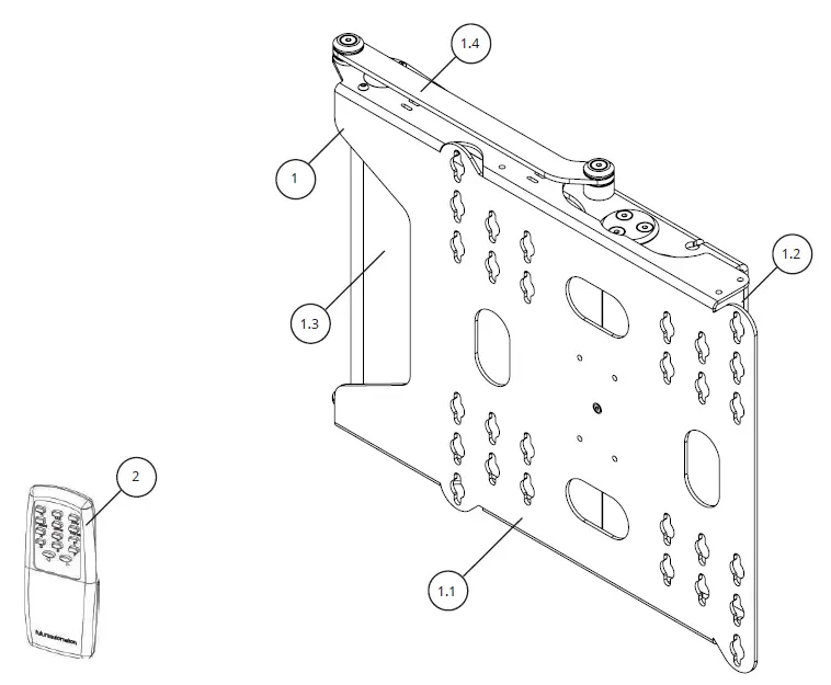
PACKAGE CONTENTS
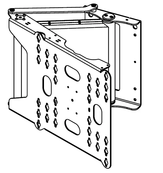
- PSE90 MECHANISM
1.1 – SCREEN MOUNT PLATE
1.2 – WALL MOUNT PLATE
1.3 – MECHANISM COVER
1.4 – LINK ARM - INFRARED (IR) REMOTE CONTROL
ITEMS NOT SHOWN ON PAGE - PSE90 CONTROL BOARD (INSIDE PSE90 MECHANISM)
- PSE90 ACCESSORY PACK
4.1 – X2 AAA BATTERIES
4.2 – MAINS POWER LEAD
4.3 – INFRA-REF CONTROL LEAD
4.4 – CAT5 LEAD WITH RJ45 CONNECTOR
4.5 – SCREEN FIXINGS PACK (MULTI-PACK OF NUTS, BOLTS AND WASHERS)
INITIAL TESTING
Before installing of the PSE90 mechanism, the following should be checked;
- There is no damage to any part of the PSE90 mechanism, control board, or wiring.
- All internal and external mechanism wiring is secure.
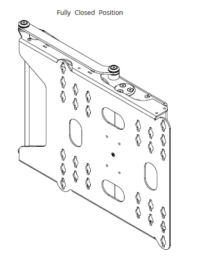
- The mechanism is in the fully CLOSED position.
- The mechanism operates correctly. This can be tested by moving the mechanism between the CLOSED and OPEN positions using the IR remote (Refer to page 14 for operating instructions)
WARNING: THE PSE90 MECHANISM DOES NOT HAVE AN ANTI-JAM CAPABILITY.
THE MOTOR DRIVE SYSTEM WILL CONTINUE TO MOVE UNTIL A LIMIT SWITCH IS CONTACTED. KEEP HANDS AND ANY OBJECTS CLEAR OF MECHANISM DURING OPERATION TO REDUCE RISK OF DAMAGE OR INJURY.
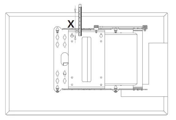
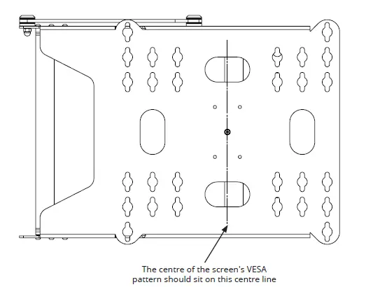
CALCULATING MOUNTING HEIGHT
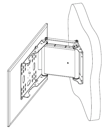
- Carefully offer the PSE90 mechanisms uprights to the back of the screen, lining up the screens VESA holes with the corresponding slots on the PSE90 Screen Mount Plate.
2. Measure from the top of the screen, down to the top mounting holes on the Wall plate (dimension X as indicated above) to determine positioning of the top wall fixing holes.
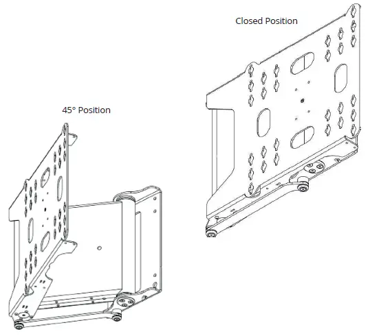
OPENING
THE BRACKET
- Hold the PSE90 by the wall plate, upside down (link arm underneath as shown) on a soft, non-abrasive surface that is free from any obstructions.
- Make sure the power is connected and press the HOME button on the remote control. This will open the PSE90 to the 45 degree position.
Closed Position 45° Position 3 - Once the bracket has stopped moving, remove the power and turn the PSE90 the correct way up.
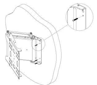
WALL MOUNTING
- The top fixing holes for the PSE90 Wall Plate should be located the distance of Dimension X (previously measured) down from the top of the desired screen position.
- Fix the top two fixings to the wall, 200mm apart and symmetrically about the center line of the wall plate.
- Check that the top two fixings are level, then hang the mechanism onto the two fixings using the keyhole slots on the Wall Mount Plate.
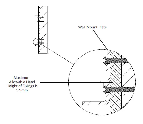
- Drill and screw the remaining six fixings in place using the holes in the Wall Mount Plate as a template.
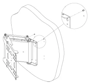
NOTE: THE WALL FIXING HEADS SHOULD NOT PROTRUDE MORE THAN 5.5MM FROM THE WALL MOUNT PLATE
NOTE: IT IS THE INSTALLERS RESPONSIBILITY TO CHOOSE THE APPROPRIATE FIXINGS WHEN ATTACHING TO THE WALL AND TO ENSURE THE MECHANISM IS SECURE AND SAFE BEFORE OPERATING.
CABLE ROUTING
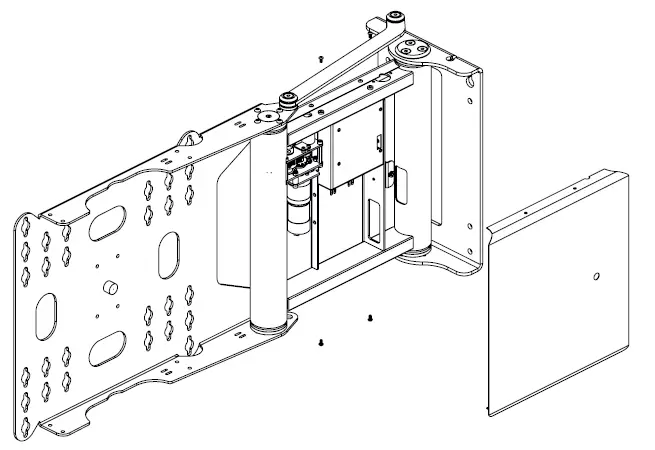
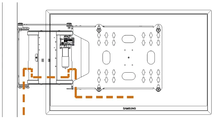
- Once fitted to the wall, the PSE90 rear arm covers can be removed to allow easy cable routing. This is best done in the 90 degree OUT position. To open the bracket, plug in the mains power and press the OUT button on the IR Remote (Refer to page 14 for Operating Instructions.)
- Once in the OUT position, remove the mains power and remove the 4 x M4 bolts that secure the rear arm cover to the PSE90.
3. Route TV power and signal cables through the mechanism as directed below. Ensure that enough clack is left for the movement of the mechanisms to avoid putting stress on the cables. All cables should also be well secured and kept as low profile as possible.
4. Replace the rear arm cover by re-securing the 4 x M4 bolts removed in step 2.
SCREEN MOUNTING
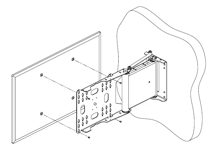
- Secure the screen to the Screen Mount Plate using the bolts and washers provided in the Fixing Pack as shown below. If the Screen has recessed mount holes, or if you need to space the screen off for clearance, use the spacers provided in the Fixings Pack. This is best done in the 90 degree out position. To open the bracket, plug in the mains power and press the OUT button on the IR Remote (Refer to Page 14 for Operating Instructions.)
FINAL CHECKS
- Make sure that both rear arm covers are fully secured to the mechanism.
- Check that there are no obstructions in the mechanisms movement (e.g. Cables caught between the Screen Mount Plate and Rear Arm.)
- Check that the mechanism is square and level on the wall.
MECHANISM PRESETS
- The PSE90 has standard IN and OUT positions, as well as 7 programmable preset positions linked to the buttons shown below.
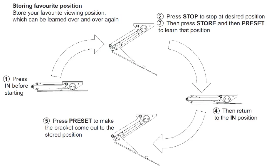
2. To overwrite any of the preset positions, use the IN, OUT and STOP buttons to take the mechanisms to the desired position. Then press the STORE button, followed by the desired preset button (HOME, PRESET or A-F). These buttons will need to be pressed within two seconds of each other.
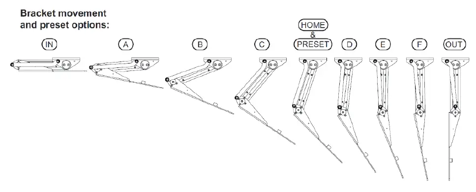
NOTE: THE PRESET POSITIONS WILL NOT BE ACTIVE UNTIL THE MECHANISM HAS OPENED TO ITS FULLY OUT POSITION AND THEN CLOSED TO THE FULLY IN POSITION.
NOTE: IF THE MECHANISM IS MOVING AND THE POSER IS CUT, TO REVISE ALL POSITIONS THE MECHANISMS NEEDS TO GO BACK TO THE IN POSITION, AFTER WHICH THE PREVIOUSLY STORED PROGRAMMED POSITIONS WILL BE RETAINED.
GENERAL CONTROL
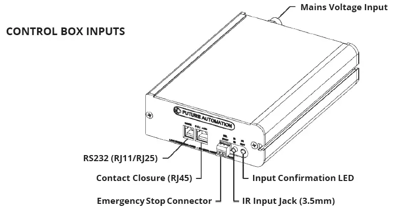
This mechanism has multiple standard control methods, each of which requires a different input method to the control box. For ease, the input sockets on the control board are labelled below.
(Control box size and style may vary to image shown)
MECHANISM EMERGENCY STOP CONNECTOR
This mechanism features an Emergency Stop Connector, which MUST be plugged into the control box in the connector labelled above for the mechanism to operate. If this connector is not plugged in, the Input Confirmation LED will be permanently lit. As per the red plastic tag attached to the Emergency Stop Connector (and shown below), the small loop of wire in this connector is designed to be replaced by a third party safety mechanism.
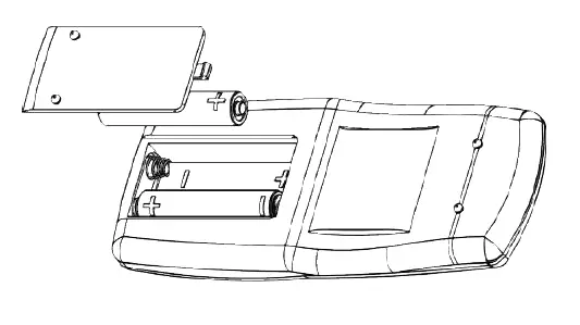
REPLACING MECHANISM BATTERIES
The standard Future Automation Infrared (IR) remote control required x2 AAA batteries to operate. These are provided with the mechanism in the Accessories Pack. These batteries can be replaced as the per the image below.

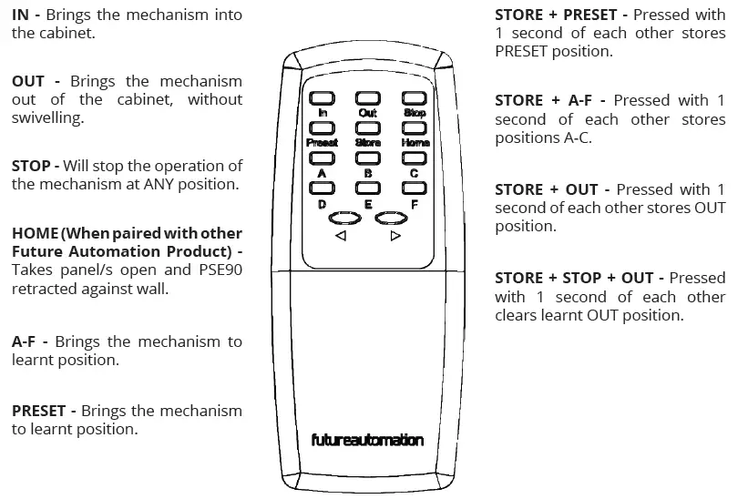
INFRARED (IR)
This Mechanism can be controlled via the supplied 14 button Infrared (IR) Remote Control, pair with the supplied Infrared (IR) lead and sensor.
The mechanism’s functions can be controlled by plugging the Infrared (IR) lead and sensor into the 3.5mm IR Input Jack shown on the General Mechanism Control page.
Confirmation of Infrared (IR) input will be shown by a single flash of the large green LED located on the end of
the control box.
As Infrared (IR) control works over line of site, the Infrared (IR) sensor must be directly viewable from what ever
location the remote control is being used from.
Infrared (IR) Remote Control Button Layout
IMPORTANT
Only buttons indicated above are functional with the product. Any other button press will STOP the mechanism.
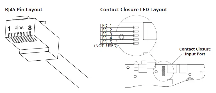
CONTACT CLOSURE
This Mechanism can be controlled via Contact Closure, utilising the 8 Pin RJ45 Connector attached to a length of
CAT5 (Type 568A or 568B) cable.
The mechanism’s functions can be controlled by plugging this into the RJ45 port on the mechanism control
board, then shorting pins 1-8 on this connector as shown in the Contact Closure Input Table below.
Confirmation of Contact Closure input will be shown by a single flash of the large green LED located on the end
of the control box, as well as illumination of the corresponding Contact Closure LED on the printed circuit board
as shown below.
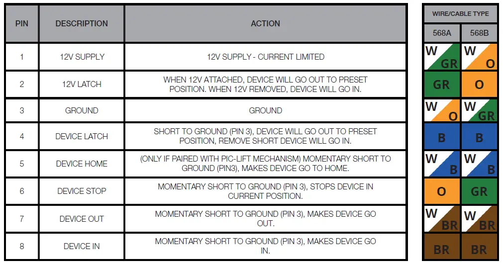
Contact Closure Input Table
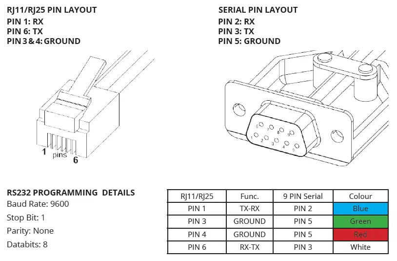
RS232 CONTROL
This Mechanism can be controlled via RS232, utilising a 6 Pin RJ11/RJ25 connector OR 9 Pin Serial connector
attached to a length of 6 core cable.
The mechanism’s functions can be controlled by plugging this into the RJ11/RJ25 port on the mechanism control
box, then inputting the RS232 commands shown in the RS232 Input Table below.
Confirmation of Contact Closure input will be shown by a single flash of the large green LED located on the end
of the control box.
RS232 INPUT TABLE
IMPORTANT – Ensure all protocols are entered exactly as written below, including Carriage Return (ENTER / ASCII 13)
EUROPEAN OFFICE
Address: Unit 6-8, Brunel Road, Bedford, Bedfordshire, MK41 9TG
Phone: +44 (0) 1438 833577
Email: [email protected]
Office Hours:
Mon – Fri 8:00 to 17:30 GMT
Saturday & Sunday – Closed
NORTH AMERICAN OFFICE
Address: Enterprise Park,
127 Venture Drive, Dover,
NH, 03820
Phone: +1 (603) 742 9181
Email: [email protected]
Office Hours:
Mon – Fri 7:00 to 17:00 EST
Saturday & Sunday – Closed