
Bard Hvac WALL MOUNT, I-TEC & Q-TEC Air Conditioners and Heat Pumps User Manual
General Information
The User’s Application Guide covers a wide range of heating and cooling products manufactured by Bard Manufacturing Company. It is intended to be a general guide for care and operation of typical systems and covers the most important features you should be aware of and are responsible for as the user of the equipment.
Because our product offerings are so varied and can be equipped with many features and options, it is not possible to cover all aspects of what your specific system may be configured for. Some systems may be quite simple in features to provide basic cooling and possibly heating, while other systems may also incorporate various ventilation technologies, dehumidification circuits and many different internal controls as well as room temperature controls. Therefore, you should request a detailed operation sequence and explanation of any special features from your installer and/or service company and also have them instruct you as to any routine maintenance procedures you are responsible for.
Overview
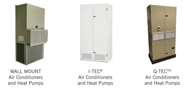
The User’s Application Guide and Technical Product Overview covers the following products:
The User’s Application Guide and Technical Product Overview covers the following topics:
- Documentation provided by Bard for proper use of your new product.
- Unit installation guidelines.
- Routine unit maintenance.
- Unit operation.
- Unit troubleshooting.
Please use this guide as a general overview regarding unit application, maintenance and troubleshooting. Refer to product installation instructions and supplemental documentation provided with the unit or go to www.bardhvac.com for detailed individual product information.
Documentation
There are two sources of valuable information for your new Bard product:
- Documentation provided with your unit, normally located inside the unit control panel during shipping. This information should be saved once the unit is installed for future maintenance reference or to answer questions about equipment after installation.
- Documentation provided on the internet at www.bardhvac.com. This may be accessed from a desktop computer at the office, a laptop or an internet-capable cell phone at the worksite. Up-to-date documentation is available, along with specification sheets and other valuable resources regarding your new Bard product.
Unit Literature Assembly – Documentation Provided with Your Unit
Bard products are shipped with documentation that when used by a technician with cooling and heating knowledge, can ensure that your product is installed safely, performs optimally and achieves the longest life cycle possible.
Shipped literature includes the following:
- User Manual (this document)
- Installation Instructions
- Replacement Parts Manual
- Wiring Diagrams
- Warranty Information
Unit Installation
Installation plays a key part in unit functionality, performance and safety. Product securing and placement, duct design and supply/return location, electrical routing and condensate and defrost drainage all play key roles in making sure a unit will perform per the design specifications.
WALL MOUNT Products – Mounting the Product on a Wall Surface
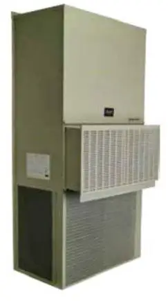
Outdoor products are normally mounted to an exterior wall surface, including brick, cement block, metal or wood construction. These products are labeled as “WALL MOUNT” units. Before installation begins, the wall surface should be inspected by a construction professional to ensure it will support the weight of the unit and accessory items. Approximate weights are available from the product specification sheet, and a safety factor should be designed into the installation. Typical fasteners to attach the unit to the wall using the integrated mounting flanges on both sides of the unit include tap cons, bolts, studs and other fastening devices. The selection of the fasteners to be used needs to be reviewed by a construction professional and decided upon based on the wall construction and fastener strength required. It is important to follow all guidelines and procedures covered in the installation instructions manual provided for the product.
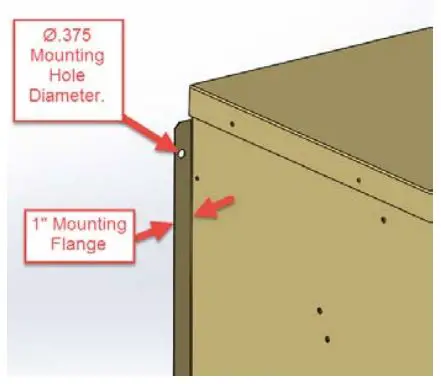
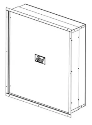
Built-In Mounting Flange Detail:
Outdoor WALL MOUNT products include a mounting flange that is part of the cabinet construction. Ø.375″ holes are provided for unit mounting unless specified otherwise in installation instructions.
Specification Sheets:
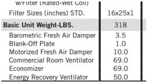
Unit specification sheets provided at www.bardhvac.com include basic unit weights and dimensions (see example below). Ventilation options and other accessories must be added into the total weight of the unit.
Specification Sheet Example
WALL MOUNT Products – Clearances for Outdoor Condenser Fan Airflow
Unit placement and avoidance of obstructions outside the structure are very critical to unit performance. Avoid installing the unit in areas that will obstruct outdoor condenser fan airflow or create “pockets” of heated air being exhausted from the condenser coil. Solid construction fences should not be placed directly in front of the unit without provisions for condenser airflow. Solid exterior walls need to be spaced as far away from units as possible to avoid pockets of heated air causing condenser air recirculation.
Solid barriers located too close to the face or side surfaces (condenser fan inlet and outlet) of the WALL MOUNT can both impede airflow and force heated air to short circuit (be returned) from the condenser outlet to the condenser inlet. Either condition will effectively raise the condensing temperature and pressure reducing cooling capacity and efficiency. In extreme cases, the unit may fail to operate due to high refrigerant pressures inside the unit, and compressor and/or fan motor failure may occur. Clearances given in installation instructions ensure components can be serviced and maintenance can be performed when needed.
National and local electrical codes must be reviewed before unit installation.
Always use common sense when installing products, follow unit clearances given in the installation instructions and contact local Bard distributors when additional knowledge is needed regarding unit clearances for proper unit functionality.
WALL MOUNT Products – Clearances for Indoor Supply and Return Airflow
The Bard unit should be placed in an area where the supply (leaving conditioned air) and return (unit air intake) air paths will be unrestricted. Avoid placing objects in the structure within 24″ of the return (unit air intake) grille. Avoid placing objects directly in the path of the supply (conditioned) air grille. This will inhibit the “throw” of the supply air throughout the structure and reduce the cooling and/or heating ability of the unit; in extreme cases, this may cause evaporator coil freezing issues. Supply air must be able to freely circulate conditioned air throughout the structure. Adjustment of supply grille deflectors is often necessary to ensure proper room circulation.
Ducted applications should not exceed the rated duct static pressures given in the unit specification sheets. Special requirements for duct construction and distances to combustible materials need to be followed per the installation instructions when electric heating is used.
WALL MOUNT Products – Condensate and Defrost Drainage
Condensate drainage for air conditioning units needs to be planned before installation. Your new Bard WALL MOUNT product includes provisions to allow condensate water to exit the bottom of the unit. If condensate water is to be routed away from the unit, adequate drain sizing needs to be provided to allow proper drainage for condensate water generation. During normal air conditioning operation, large amounts of condensate water is generated inside the unit as moisture is extracted from the supply air. This is collected in an evaporator pan and drained to either a drainage system (indoor products) or outside the unit cabinet (outdoor products). Evaporator drain traps are not necessary for any of our wall mounted outdoor products, and the use of “standing water” U-shaped traps may be prone to freezing in certain climate zones. Defrost water drainage from heat pump units needs to be planned before installation. During seasons requiring heating operation, the unit will need to warm the condenser coil to remove frost build-up (defrost). Outdoor heat pump products include holes in the unit base under the condenser coil for proper water drainage when in the heating defrost cycle. Avoid placing the unit on a pad or blocking the base drainage holes under the condenser coil without proper allowances (6″ recommended) for water drainage due to damage caused by freezing conditions. Without proper drainage, defrost water may freeze causing ice build up and damage the lower portion of the condenser coil.
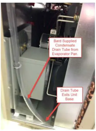
Condensate Water Drainage: Unit condensate water exits the base of the unit during cooling operation.
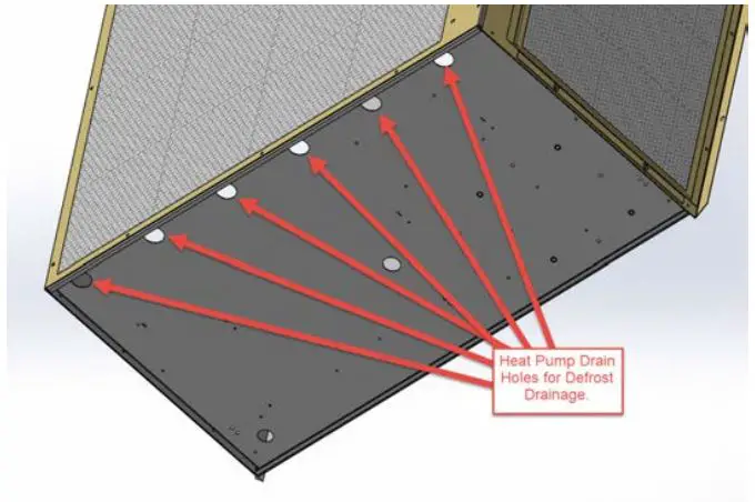
Defrost Water Drainage: Holes are provided in the front of the unit base for heat pump condensate water drainage.
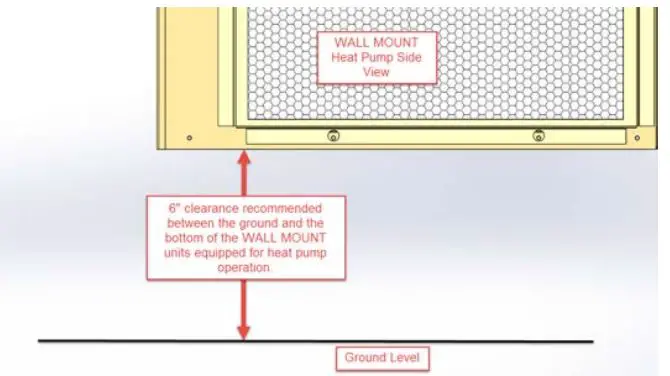
Defrost Water Drainage: 6″ clearance is recommended under WALL MOUNT Heat Pump products to allow proper defrost water drainage.
I-TEC and Q-TEC Products – Installing the Product Inside a Room

Indoor products are normally supported by the floor surface and are adjacent to an interior wall surface, including brick, cement block, metal or wood construction. These products are normally labeled as “I-TEC” or “Q-TEC” units. Before installation begins, the floor surface should be inspected by a construction professional to ensure it will support the weight of the unit and accessory items. Approximate weights are available from the product specification sheet, and a safety factor should be designed into the installation.
A sheet metal sleeve is normally installed in the wall allowing vent and condenser fan air to enter and exit the unit. Different sleeve depths are available for installation into various wall depths. Typical fasteners to attach the sleeve to the outside surface of the wall include tap cons and other fastening devices. The I-TEC or Q-TEC unit is then slid up to the wall surface and connected to the sleeve using screws. Trim kits are available to enclose gaps between the wall surface and the unit. A louver grille is used to cover the external wall opening and fasteners used during sleeve installation.
Wall Sleeve:
Wall sleeves allow for outdoor air to enter and exit the unit inside the room.
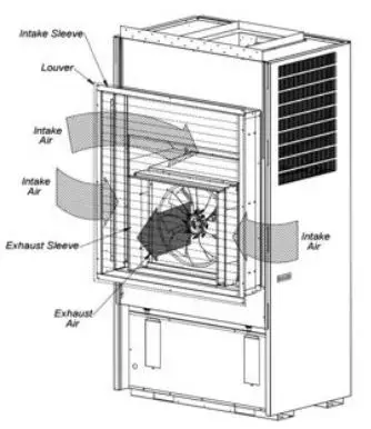
Air Paths:
Air paths through the unit allow for cooling operation and fresh air to enter the structure (I-TEC shown).
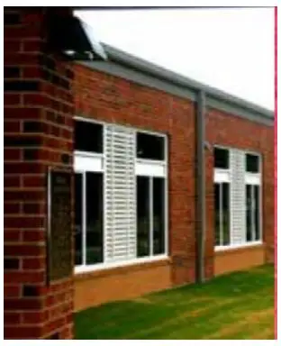
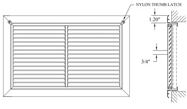
Louver Installation:
Outdoor louvers provide an esthetically pleasing look to the installation and cover the unit opening (I-TEC shown).
I-TEC and Q-TEC Products – Clearances for Outdoor Condenser Fan Airflow
Solid barriers located too close to the face of the outdoor louver of the I-TEC or Q-TEC can both impede airflow and force heated air to short circuit (be returned) from the condenser outlet to the condenser inlet. Either condition will effectively raise the condensing temperature and pressure reducing cooling capacity and efficiency. In extreme cases, the unit may fail to operate due to high refrigerant pressures inside the unit, and compressor and/or fan motor failure may occur. It is recommended to allow 15′ (457.2 cm) in front of unit louver for proper condenser airflow. Always use common sense when installing products, follow unit clearances given in the installation instructions and contact local Bard distributors when additional knowledge is needed regarding unit clearances for proper unit functionality.
I-TEC and Q-TEC Products – Clearances for Indoor Supply and Return Airflow
The Bard unit should be placed in an area where the supply (leaving conditioned air) and return (unit air intake) air paths will be unrestricted. Avoid placing objects inside the room within 24″ of the return (unit air intake) louvers or grille. Avoid placing objects directly in the path of the supply (conditioned) air grilles. This will inhibit the “throw” of the supply air throughout the structure and reduce the cooling and/or heating ability of the unit and in extreme cases may cause evaporator coil freezing issues. Ducted applications should not exceed the rated duct static pressures given in the unit specification sheets. Special requirements for duct construction and distances to combustible materials need to be followed per the unit installation instructions when electric heating is used.
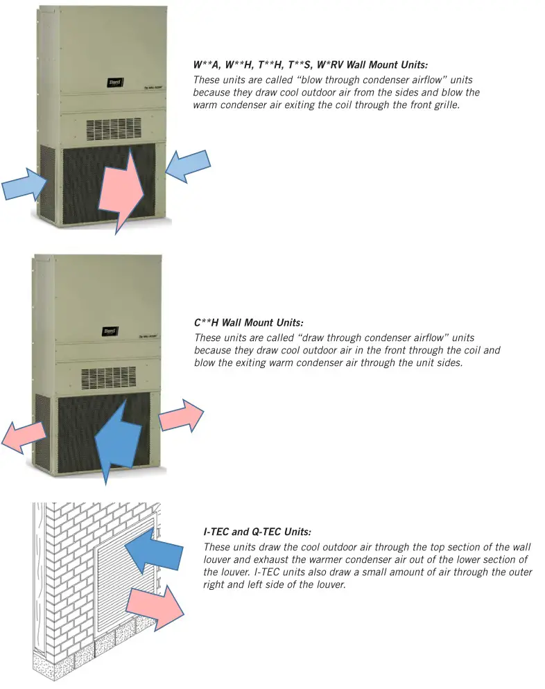
I-TEC Air Path
The I-TEC product has been engineered for extremely quiet unit operation and has multiple air paths for air entering and exiting the unit. Room air enters the upper sides to be conditioned (cooled) inside the unit and exits the unit top. The unit will either be ducted to supply registers or have a supply air plenum box installed. A supply air plenum box allows quiet operation without ducting the air leaving the unit. Room air also enters the bottom of both front doors during ventilation operation.

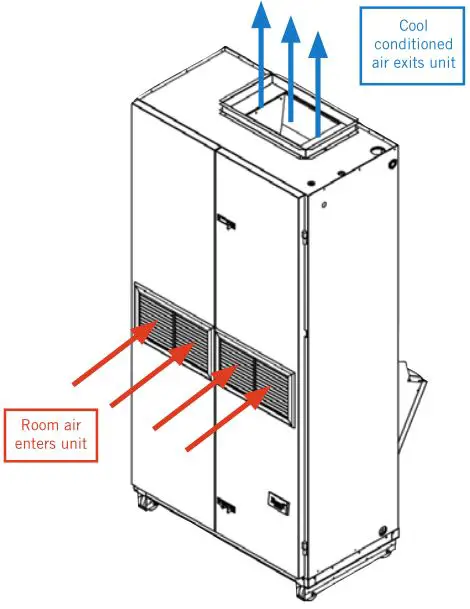
Q-TEC Air Path
The Q-TEC product has been engineered for efficient, economical unit operation and has a mid-mounted front grille for air entering the unit. The unit will either be ducted to supply registers or have a supply air plenum box installed. A supply air plenum box allows quiet operation without ducting the air leaving the unit.
The I-TEC and Q-TEC product installation instructions contain additional information regarding unit air paths and required clearances. This information may be accessed at www.bardhvac.com.
I-TEC and Q-TEC Products – Condensate Drainage
Condensate drainage for Bard indoor cooling units is a very important part of unit installation. During normal air conditioning operation, large amounts of condensate water are generated inside the unit as moisture is extracted from the supply air. This is collected in an evaporator pan and needs to be drained to an external drainage system. Your new Bard product includes provisions to allow condensate water to exit the unit and fittings will need to be field supplied to connect the unit drain to the building. Adequate drain sizing needs to be provided to allow proper drainage for condensate water generation and restriction in drain lines should be avoided. Evaporator drain traps are not necessary unless required by local codes.
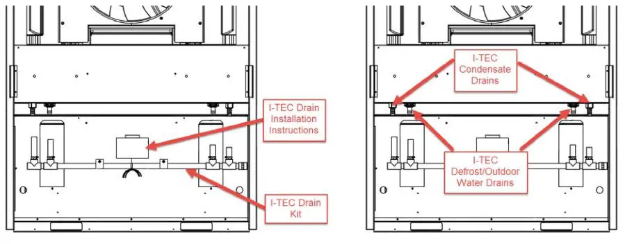
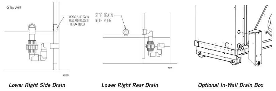
Defrost water for heat pump operation and outdoor water entering the condenser area also needs to be drained out of the unit. The I-TEC product uses a combined defrost and outdoor water drainage system. The Q-TEC has a combined defrost and evaporator drain connection unless an optional in-wall drain box is used. Outdoor water exits the Q-TEC through the wall sleeve. Follow all instructions provided in the unit installation instructions regarding drain connections and sleeve installation to avoid water leakage inside the building or structure.
I-TEC Drain System:
The I-TEC drainage system consists of a manifold drain kit that combines all drains behind the unit to allow connection to the building system.
Q-TEC Drain System:
The Q-TEC drainage system consists of a lower right side or lower right rear connection fitting. An optional in-wall drain box may also be purchased as an accessory that allows separate evaporator and defrost water drainage.
All Products – Power Supply Verification
It is very important to follow all electrical and mechanical safety guidelines and instructions provided in the product installation instructions. Failure to do so may result in death, injury or product damage.
A proper power supply to your new Bard unit is very important. Be sure to verify the following with a multi-meter or other power measuring device before applying power to your Bard product.
Field-Supplied Voltage
Electrical voltage ratings and proper voltage operating ranges are provided in the unit specification sheets and installation instructions. It is important that power supplied to the unit stay in the specified operating voltage range. Voltage above or below the minimum operating value given could result in improper unit startup, unit shutdown, low unit performance, improper thermostat and unit controller operation, compressor damage and premature failure of functional parts. As a general guideline, it is always best if the power source for the unit supplies the nominal electrical rating value given in the specification sheets, installation instructions and unit serial plate for the product being used. To do so will provide the best unit performance possible from your new Bard product.
Single and Three Phase Power
Bard products are available in single and three phase power options. It is important to connect the proper phase listed on the unit serial plate. Three phase power is often used to reduce energy usage, and units rated for 3 phase operation are equipped with a phase monitor safety device. The phase monitor will not allow unit operation with improper phase connection and a red LED light on the monitor indicates phase wiring issues. Connecting 3 phase power to a single phase unit will result in component damage and improper unit operation. Connecting single phase power to a 3 phase unit will also result in component damage and improper unit operation.
Hertz (Frequency)
Bard products are available in 50hz and 60hz power options. It is important to connect power with the proper hz value listed on the unit serial plate. 60hz power is often used in the United States and Canada and units rated for 50hz operation are normally for international sales outside of this area. Connecting 50hz power to a 60hz unit not rated for 50hz operation may result in component damage and improper unit operation. Some equipment may be rated for 50/60hz operation. Review the unit specifications and installation instructions for further information regarding the power requirements of the unit.
The product installation instructions and unit specification sheets contain additional information regarding unit electrical data. This information may be accessed at www.bardhvac.com.
Unit Maintenance
All Products – Filters and Filter Servicing
All Bard products contain air filters that must be cleaned or replaced on a regular basis.
Keeping air filter(s) clean is the single most important responsibility of the user of the equipment. Each type of system must be equipped with an air filter(s) in the indoor circulating air system to clean the air, keep the system itself clean for peak efficiency and capacity and prolong the useful life of the equipment. DO NOT operate the system without the proper air filters. Filters should be inspected at least monthly and replaced or cleaned (depending on type) as needed. The useful life of an air filter can vary widely depending upon application and use of the equipment, and it is critical to monitor filter condition and establish an acceptable maintenance schedule. Failure to do so will increase operating and repair costs, decrease capacity and efficiency and shorten the service life of the equipment. A common symptom of a dirty filter in the cooling mode is a freeze-up of the indoor coil. The air filters used may be a disposable (throwaway) type or may be a cleanable type that can be thoroughly cleaned, rinsed and reused many times. It is important to make sure that the correct filter size and type for your system is always used. If there is any question as to acceptable filter size or type, review the installation instructions for the specific equipment involved, if available. Otherwise, consult with your installing dealer or service company. Most equipment can have the filters inspected and serviced by the user with no problems. In some instances, because of equipment design or specific installation conditions, it may be necessary to have this procedure done by a qualified service company. Have your installer or service company show you where the filter(s) are and demonstrate the service procedure or make arrangements for them to provide this service on an as-needed basis.
Outdoor Unit Wall Mount Room Air Filters
Wall mount filters are normally accessed from the outside of the building. Bard does offer a return air grille with a filter frame built-in for indoor filter access. The return air filter grille is not acceptable as the only source of filtration if vent options are installed in the wall mount unit.
Return Air Filter Grille:
Bard offers the RFG return air filter grille, which may be used in applications where outdoor air is not brought into the structure through vent options. If vent options are used, the filter tray inside the Bard Wall Mount unit must be used.
The product installation instructions contain additional information regarding unit maintenance. This information may be accessed at www.bardhvac.com.
WALL MOUNT Products – Filters and Filter Servicing
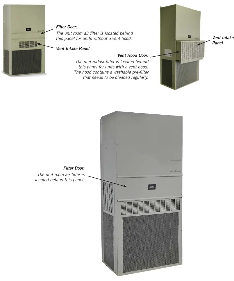
The built-in filter tray and room air filters in the wall mount are located in the middle of the cabinet below the indoor blowers. Units with vent options will have a washable screen behind the vent intake panel.
I-TEC Indoor Products – Filters and Filter Servicing
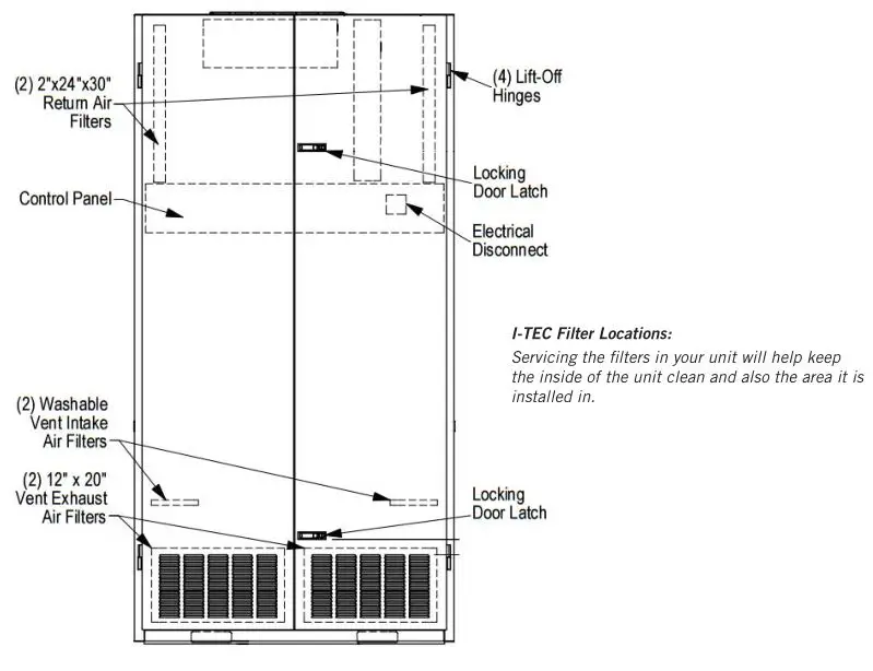
The I-TEC indoor air conditioners and heat pumps have multiple filters that must be maintained and inspected when servicing the unit. Filters play an important part in proper unit operation and prevent dirt and dust buildup inside the I-TEC and the room the unit is installed in. To access the unit filters, open the front hinged doors by unlocking the door latches. The doors fold outward and are on hinges with lift-off pins. Use care when opening doors. If doors are lifted off of the hinge pins, use care as the dense insulation used for sound reduction causes the doors to be heavy.
The upper section of the unit contains two 2″ x 24″ x 30″ throwaway filters as standard with every unit. MERV ratings of the filter are available up to MERV13. These filters filter the air used for cooling inside the classroom or structure and should be changed regularly.
If the unit has an air intake vent option installed, two 1″ x 12″ x 20″ filters are located in the lower section of the front doors behind the louvers. These filters help keep the vent option clean and operating properly.
Two washable filters are also installed in the air intake vent option. These should be inspected during servicing and cleaned when necessary. The washable filters are used to remove dirt and dust from outdoor air that is entering the vent area. If at any time these filters are damaged, they must be replaced with Bard-approved filters.
The I-TEC product installation instructions contain additional information regarding unit maintenance. This information may be accessed at www.bardhvac.com.
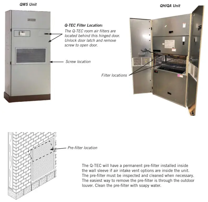
Q-TEC Indoor Products – Filters and Filter Servicing
The Q-TEC indoor air conditioners and heat pumps have two room air filters that must be replaced when servicing the unit. Filters play an important part in proper unit operation and prevent dirt and dust buildup inside the Q-TEC and the room the unit is installed in. To access the unit filters, open the front hinged door by unlocking the door latch. The door folds outward and is on hinges with lift-off pins. Use care when opening doors. If the door is lifted off of the hinge pins, use care as the insulation and louver grille cause the door to be heavy.
The upper section of the Q-TEC contains two 1″ throwaway filters standard with every unit. These filters filter the air used for cooling inside the classroom or structure and should be changed regularly.
The Q-TEC product installation instructions contain additional information regarding unit maintenance. This information may be accessed at www.bardhvac.com.
All Products – Coil Cleaning
The outdoor coil must be kept clean and free of any airborne debris, which can accumulate over time. Large volumes of air are circulated over the coil, and airborne debris such as lint, dust, materials shed from trees, paper or other types of airborne material that can become airborne can collect on the entering coil surface. The outdoor coil must dissipate heat during the cooling mode and for a heat pump, also absorb heat during the heating mode. If the coil is dirty and matted with debris, the airflow across the coil will be reduced causing poor performance, increased operating run time and associated utility bills and in extreme conditions can shorten the useful life of the equipment.
Depending on the specific equipment involved, the surface that can accumulate debris can be on the opposite side that is exposed to view when standing in front of the machine. Closely review the machine when operating to see which direction or path the airflow takes as it moves through the machine. If the air inlet side of the coil is hidden, try to observe the back (hidden) side by looking into the side grilles, using a flashlight if necessary. While the user of the equipment needs to be aware of the potential of clogging of the outdoor coil surface, actual cleaning of the outdoor coil should not be attempted under most circumstances. If the user should attempt this procedure on their own, never do so without first having the installing dealer or service company instruct you in the proper procedure and technique.
WARNING: Do not open or enter the equipment without first turning off the electrical service disconnect. Failure to do so can result in personal injury due to moving parts and/or electric shock hazard resulting in death.
Other conditions that can cause reduction of airflow across the outdoor coil are flowers, shrubbery or other growth too near the outdoor coil air inlet and outlet openings. These living things, especially as they mature and grow, will be just as effective in blocking the airflow and create the same problems as will stacking things against the equipment. These conditions can be easily managed and controlled by the user, as they do not require actually entering into the equipment enclosure, which should only be done by qualified service technicians.
Equipment Corrosion Protection
- Avoid having any lawn sprinkler spray directly on the equipment, especially if from a brackish water source.
- In coastal areas or corrosive environments, locate equipment as far away from the corrosion source as feasible. Units exposed directly to salt spray should be coated by a secondary protective coating operation to reduce corrosion on copper tubing, fasteners, motors and other metal parts. Coils should be ordered with a corrosion protective coating. Contact Bard for coating options.
- Frequent cleaning and waxing of the cabinet using a good automobile polish will help extend its original appearance and protect painted surfaces.
The product installation instructions contain additional information regarding unit coil cleaning. This information may be accessed at www.bardhvac.com.
All Products – Condenser Airflow
Unit Operation
Air-to-Air Cooling Products (Air Conditioners)
The cooling mode operates similar to a refrigerator, removing heat from inside the conditioned space and rejecting it outside of the space being controlled. There are three main parts of the system:
- The evaporator (indoor) coil where cold refrigerant absorbs heat from the air, which circulates from the conditioned space through the machine and is returned to the space at a lower temperature and with some of the humidity (moisture) removed. The moisture exits through a condensate drain system. A motor/blower assembly moves the indoor air through the system.
- The compressor, which is a sealed pump that moves the refrigerant through the system.
- The condenser (outdoor) coil where the heat that was absorbed from the indoor space is discharged to the outdoor environment. A motor/fan system moves the outdoor air across the condenser coil. A properly sized air conditioner cannot cool a structure off rapidly and instead will pull down the temperature slowly. It also will remove a certain amount of moisture (humidity) from the circulating airstream in the process. It may take several hours to pull down a hot, moist building or structure on initial startup or anytime the system has been turned off for a long period of time. It is generally best to set the thermostat at a comfortable temperature and let it control the system as needed, rather than turning it on and off.
Moisture (humidity) removal with a conventional air conditioner (cooling) unit, or heat pump when operating in the cooling mode, is not directly controlled and is a by-product of the unit operating to control temperature in response to the temperature (thermostat) control device. Oversized equipment can easily control temperature but will have short run-times, thus reducing its ability to remove moisture from the circulating air stream.
There are also many additional influences that can affect humidity levels within the conditioned space such as laundry appliances, cooking, showers, exhaust fans and any other items that can generate moisture or affect its removal from the space. Therefore, while operation of the air conditioning or heat pump system in the cooling mode will remove some amount of moisture as it reduces the air temperature, precise humidity regulation in the conditioned space cannot be assured and additional equipment such as a dedicated dehumidifier may be required.
Air-to-Air Cooling and Heating Products (Heat Pumps)
A heat pump is a refrigerant-based system that has additional components and controls that both heats and cools using a compressor for both modes of operation. Most heat pumps will also be equipped with some amount of electric heat to supplement the heating capacity of the compressor system on an as-needed basis. This operation is entirely automatic and is controlled by the indoor thermostat and possibly also an outdoor thermostat.
Cooling Mode
The cooling mode of a heat pump is exactly the same as that described for an air conditioner in the above section.
Heating Mode
The system operates in reverse cycle, meaning that it absorbs and moves heat from the outdoors and transfers it indoors to be rejected into the circulating air stream. Even though it seems cold to humans, there is usable heat that can be extracted efficiently from the outdoor air down to 0ºF, although the colder the air is there is less heat to extract and the operating efficiency is diminished.
Defrost Cycle
When operating in the heating mode, the outdoor coil will be colder than the outdoor air that is forced over it by the fan system. When the outdoor air temperature is above approximately 40°F, moisture can accumulate on the coil and it will drain down and out the base of the unit. As the air temperature gets below approximately 40°F, the coil temperature will start to drop below 32°F, and frost or ice will begin to form on the coil.
An automatic defrost system keeps track of system run time when the outdoor coil temperature is in the freezing zone and will initiate a defrost cycle at the appropriate time. The unit continues to operate during the defrost cycle, but the outdoor fan motor will stop and the reversing valve will shift positions to flow hot refrigerant gas through the outdoor coil to melt the accumulated frost. Water will start to drain freely from the unit, and steam may be emitted from the unit.
The length of the defrost cycle will vary depending upon actual outdoor temperature, humidity levels and amount of accumulated frost. It could range from 1-2 minutes up to but not exceeding 8 minutes. When the defrost cycle terminates, the reversing valve will shift back to heating mode and the outdoor fan will restart. There is typically a large puff of steam emitted as the fan restarts. When the heat pump shifts from cool to heating mode, from heating to cooling mode and especially during defrost cycles, there will be a pressure transfer sound heard as the reversing valve redirects the flow of refrigerant. This is commonly described as a hissing noise and is a normal sound for this type equipment.
For air source heat pumps, it is important to keep heavy snow from accumulating around the machine to the point of blocking the inlet and outlet openings to the outdoor coil section. For wall mounted or other equipment that is elevated, this should not be a factor; but for equipment installed on or near the ground, this can be an issue in areas prone to heavy and/or blowing snow. The air source heat pump cannot operate effectively and efficiently when snowbound just as a car cannot function well in heavy snow conditions.
Water-to-Air Cooling and Heating Products (Geothermal Heat Pumps)
These types of heat pumps are also commonly referred to as water source or geothermal systems. Just like the air source heat pump, they are refrigerant-based systems that both heat and cool using a compressor for both modes of operation. The primary difference is that the system uses water or antifreeze-protected water solution instead of an air-cooled outdoor heat transfer coil, and there is no outdoor motor/fan system but instead a water pump to provide adequate water flow to the system.
Cooling Mode
The cooling mode of a water-to-air heat pump is exactly the same as that described for an air conditioner in the previous Air Conditioner section, except that the outdoor coil uses water instead of air for the heat transfer medium.
Heat Mode
The system operates in reverse cycle, meaning that it acquires and moves heat from the water supply flowing through the water to refrigerant coil and transfers it indoors to be rejected into the circulating air stream.
Most water-to-air heat pumps (but not all) will also be equipped with some amount of electric heat to supplement the heating capacity of the compressor system on an as-needed basis. This operation is entirely automatic and is controlled by the indoor thermostat.
Because of the design of water-to-air heat pumps and the water temperatures involved, no defrost system is required as in air-to-air heat pumps.
Water Supply Systems
Depending upon the type and application of the water-to-air heat pump, the water side of the system could be one of the following:
- Individual closed loop buried in a trench or vertical bore hole(s).
- Individual loop submerged in a pond.
- Water supplied from a well and discharged into pond, stream, ditch or another well.
- Water supplied from a boiler/tower system, typically only in larger multi-unit installations.
Dehumidification and Ventilation Operation
Dehumidification (Air-to-Air or Water-to-Air Systems)
Many Bard systems, typically those used in schools or other commercial applications, have a dedicated dehumidification capability by having a special additional refrigeration circuit (factory-installed option only) in addition to the basic system. These special systems, sometimes also referred to as hot gas reheat, are designed to control humidity on demand from a humidity controller much the same as the basic cooling and/or heating system is controlled by a wall thermostat. Consult your installer and/or service company to determine if your installation has any of these devices and for any instructions or maintenance requirements you should be aware of as the user.
Ventilation Options (Air-to-Air or Water-to-Air Systems)
All Bard systems are available with factory-installed vent options. Most units can have ventilation field installed after unit installation.
Ventilation has multiple purposes:
- Outside air intake for occupied structures
- Positive pressurization
- Energy savings when outdoor air can be used for cooling
- Agricultural use of bringing in outdoor air and exhausting room air
- Equipment and electronics ventilation
Review product specifications and manuals for more details regarding available ventilation options and features. Product documentation is shipped with the product and also available at www.bardhvac.com.
Troubleshooting
All Units – Troubleshooting
Your Bard product is made to operate for many trouble-free years if installed properly and maintenance practices are followed. Be sure to verify that all filters are clean, and condenser coils are free of dirt and debris. Often these items may look clean at first, but upon closer inspection, show signs of dirt and debris build-up. New units on new structures may have dirt and dust in filters from the building construction process.
Thermostats and unit controllers often contain vent holes for proper sensor measurement inside the device. Make sure the thermostat or controller are not full of dirt and dust from building construction or years of use.
Verify all requirements in the installation instructions and specification sheets are met. Unit voltages, airflow clearance requirements and clean unit power without brownouts or spikes play a critical role in unit performance. If 208 VAC power is supplied to the unit, the 208V tap must be used on the 24 VAC transformer located inside the control panel. Common sense must also be used when installing the unit in an environment that may put the unit at risk of improper operation.
Helpful Hints and Good Operating Practices
The following information will help you enjoy the full comfort and benefits of your Bard cooling and heating system, maximize the performance and efficiency and help extend the life of your system.
- Always keep the equipment in peak operating condition with routine scheduled maintenance, especially for the air filters, and to assure a clean outdoor coil.
- For most efficient operation, set the thermostat at the temperature you prefer and then let it take control. If any changes to the settings are required, they should be made in small adjustments and the system be allowed time to respond. Rapid changes either up or down should not be done.
- Setting the thermostat very high does not make the system heat faster and setting it very low does not make it cool faster.
- It is not recommended to turn the system “Off” then back “On” when you need it. This can allow temperature and humidity to build up in warm weather conditions and force the system to run continuously to try and catch up. If the building is to be unoccupied for a lengthy period, it is best to adjust the thermostat to a reasonable higher (or lower—depending on the season) setting rather than turning it completely off. Upon return, the inside conditions will not be totally out of control and recovery time to desired conditions would be much shorter.
- Airflow inside the room or building is very important. Keep all supply registers open and all returns free and unrestricted. Avoid placing objects in areas that will hinder unit airflow. The heating and cooling system is designed to have a certain amount of airflow for proper operation. Therefore, closing off registers, in unused rooms as an example, could reduce airflow below acceptable levels and should not be done without review by your service company who can assess the overall situation and advise you accordingly.
- Heat pumps, especially air-to-air heat pumps, may have the system (compressor) run continuously at lower outdoor temperatures, and this is normal. The heat pump (compressor) mode is controlled by the beginning stages of the thermostat and delivers the most efficient heat. As the outdoor temperature drops off, the heat pump mode heat will also diminish (because there is less heat in the outdoor air to absorb) and must be supplemented by additional electric heat stages, which are not as efficient as the heat pump. The thermostat automatically controls everything and the backup heat will only operate on demand as needed to maintain the desired temperature.
- The thermostat or controller is the user’s primary connection to the system so it is very important to have a thorough understanding of how it works and how to use it properly. Have your installer or service company explain and demonstrate proper operation of the controls.
- Make sure you thoroughly understand how the heating and cooling system itself is intended to operate and what to expect from it. Have your installer or service company explain and demonstrate proper operation of the heating and cooling system.