
BLUERIDGE BMKH0938O Split Air Conditioner Owner’s
This appliance is not intended for use by persons (including children) with reduced physical, sensory or mental capabilities, or lack of experience and knowledge unless they have been given supervision or instruction concerning the use of the appliance by a person responsible for their safety. Children should be supervised to ensure that they do not play with the appliance. If it needs to install, move or maintain the air conditioner, please contact the dealer or local service center to conduct it first. The air conditioner must be installed, moved, or maintained by the appointed unit. Otherwise, it may cause serious damage or personal injury, or death.
Explanation of Symbols
- Indicates a hazardous situation that, if not avoided, will result in death or serious injury.
- Indicates a hazardous situation that, if not avoided, could result in death or serious injury.
- Indicates a hazardous situation that, if not avoided, may result in minor or moderate injury.
- Indicates important but not hazard-related information, used to indicate risk of property damage.
- Indicates a hazard that would be assigned a signal word WARNING or CAUTION.
Exception Clauses
The manufacturer will bear no responsibilities when personal injury or property loss is caused by the following reasons.
- Damage the product due to improper use or misuse of the product;
- Alter, change, maintain or use the product with other equipment without abiding by the instruction manual of the manufacturer;
- After verification, the defect of the product is directly caused by corrosive gas;
- After verification, defects are due to improper operation during transportation of product;
- Operate, repair, maintain the unit without abiding by an instruction manual or related regulations;
- After verification, the problem or dispute is caused by the quality specification or performance of parts and components that are produced by other manufacturers;
- The damage is caused by natural calamities, a bad using environment, or force majeure.
Precautions
Operation and Maintenance
- This appliance can be used by children aged 8 years and above and persons with reduced physical, sensory or mental capabilities or lack of experience and knowledge if they have been given supervision or instruction concerning use of the appliance in a safe way and understand the hazards involved.
- Children shall not play with the appliance.
- Cleaning and user maintenance shall not be made by children without supervision.
- Do not connect the air conditioner to the multi-purpose socket. Otherwise, it may cause a fire hazard.
- To disconnect the power supply when cleaning the air conditioner. Otherwise, it may cause electric shock.
- If the supply cord is damaged, it must be replaced by the manufacturer, its service agent, or similarly qualified persons in order to avoid a hazard.
- Do not wash the air conditioner with water to avoid electric shock.
- Do not spray water on the indoor unit. It may cause electric shock or malfunction.
- After removing the filter, do not touch the fins to avoid injury. Do not use a fire or hair dryer to dry the filter to avoid deformation or fire hazards.
- Maintenance must be performed by qualified professionals. Otherwise, it may cause personal injury or damage.
- Do not repair the air conditioner by yourself. It may cause electric shock or damage. Please contact the dealer when you need to repair the air conditioner.
- Do not extend fingers or objects into the air inlet or air outlet. It may cause personal injury or damage.
- Do not block the air outlet or air inlet. It may cause malfunction.
- Do not spill water on the remote controller, otherwise, the remote controller may be broken.
- When the below phenomenon occurs, please turn off the air conditioner and disconnect power immediately, and then contact the dealer or qualified professionals for service.
- The power cord is overheating or damaged.
- There’s an abnormal sound during the operation.
- Circuit break trips off frequently.
- The air conditioner gives off a burning smell.
- The indoor unit is leaking.
- If the air conditioner operates under abnormal conditions, it may cause malfunction, electric shock, or fire hazard.
- When turning on or turning off the unit by emergency operation switch, please press this switch with an insulating object other than metal.
- Do not step on the top panel of the outdoor unit, or put heavy objects. It may cause damage or personal injury.
Attachment
- Installation must be performed by qualified professionals. Otherwise, it may cause personal injury or damage.
- Must follow the electric safety regulations when installing the unit.
- According to the local safety regulations, use a qualified power supply circuit and circuit break.
- To install the circuit break. If not, it may cause malfunction.
- An all-pole disconnection switch having a contact separation of at least 3mm in all poles should be connected to the fixed wiring.
- Including a circuit breaker with suitable capacity, please note the following table. The air switch should be included a magnet buckle and heating buckle function, it can protect the circuit from short and overload.
- Air Conditioner should be properly grounded. The incorrect grounding may cause electric shock.
- Don’t use an unqualified power cord.
- Make sure the power supply matches the requirement of the air conditioner. Unstable power supply or incorrect wiring or malfunction. Please install proper power supply cables before using the air conditioner.
- Properly connect the live wire, neutral wire, and grounding wire of the power socket.
- Be sure to cut off the power supply before proceeding with any work related to electricity and safety.
- Do not put through the power before finishing the installation.
- If the supply cord is damaged, it must be replaced by the manufacturer, its service agent, or similarly qualified persons in order to avoid a hazard.
- The temperature of the refrigerant circuit will be high, please keep the interconnection cable away from the copper tube.
- The appliance shall be installed in accordance with national wiring regulations.
- Installation must be performed in accordance with the requirement of NEC and CEC by authorized personnel only.
- The air conditioner is a first-class electric appliance. It must be properly grounded with a specialized grounding device by a professional. Please make sure it is always grounded effectively, otherwise, it may cause electric shock.
- The yellow-green wire in the air conditioner is a grounding wire, which can’t be used for other purposes.
- The grounding resistance should comply with national electric safety regulations.
- The appliance must be positioned so that the plug is accessible.
- All wires of the indoor unit and outdoor unit should be connected by a professional.
- If the length of the power connection wire is insufficient, please contact the supplier for a new one. Avoid extending the wire by yourself.
- For the air conditioner with a plug, the plug should be reachable after finishing the installation.
- For the air conditioner without a plug, a circuit break must be installed in the line.
- If you need to relocate the air conditioner to another place, only a qualified person can perform the work. Otherwise, it may cause personal injury or damage.
- Select a location that is out of reach for children and far away from animals or plants. If it is unavoidable, please add the fence for safety purposes.
- The indoor unit should be installed close to the wall.
Working temperature range
For 09k models
| Indoor side DB/WB(°C/°F) | Outdoor side DB/WB(°C/°F) | |
| Maximum cooling | 26.7/19.4(80/67) | 54/24(129/75) |
| Maximum heating | 26.7/-(80/-) | 24/18(75/65) |
NOTICE
The operating temperature range (outdoor temperature) for cooling is -18℃(0°F)~54 (129°F) for heating is -30 (-22°F)~24 (75°F).
For models
NOTICE
| Indoor side DB/WB(°C/°F) | Outdoor side DB/WB(°C/°F) | |
| Maximum cooling | 26.7/19.4(80/67) | 46/24(115/75) |
| Maximum heating | 26.7/-(80/-) | 24/18(75/65) |
The operating temperature range (outdoor temperature) for cooling is – 20 (-4°F)~46 (115°F); for heating is -25 (-13°F)~24 (75°F).
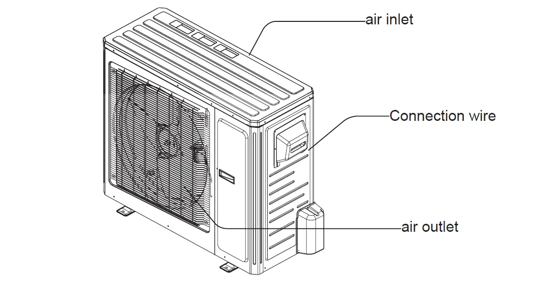
Parts Name
Outdoor Unit
NOTICE
The actual product may be different from the above graphics, please refer to the actual products.
Installation dimension diagram
Safety precautions for installing and relocating the unit
To ensure safety, please be mindful of the following precautions.
- When installing or relocating the unit, be sure to keep the refrigerant circuit free from air or substances other than the specified refrigerant.
- Any presence of air or other foreign substance in the refrigerant circuit will cause the system pressure to rise or the compressor to rupture, resulting in injury.
- When installing or moving this unit, do not charge the refrigerant which does not comply with that on the nameplate or unqualified refrigerant. Otherwise, it may cause abnormal operation, wrong action, mechanical malfunction, or even a series of safety accidents.
- When refrigerant needs to be recovered during relocating or repairing the unit, be sure that the unit is running in cooling mode. Then, fully close the valve at the high-pressure side (liquid valve). About 30-40 seconds later, fully close the valve at the low-pressure side (gas valve), immediately stop the unit and disconnect power. Please note that the time for refrigerant recovery should not exceed 1 minute.
- If refrigerant recovery takes too much time, air may be sucked in and cause pressure rise or compressor rupture, resulting in injury.
- During refrigerant recovery, make sure that the liquid valve and gas valve is fully closed and power is disconnected before detaching the connection pipe. If the compressor starts running when the stop valve is open and the connection pipe is not yet connected, air will be sucked in and cause pressure rise or compressor rupture, resulting in injury.
- When installing the unit, make sure that the connection pipe is securely connected before the compressor starts running.
- If the compressor starts running when the stop valve is open and the connection pipe is not yet connected, air will be sucked in and cause pressure rise or compressor rupture, resulting in injury.
- Prohibit installing the unit at a place where there may be leaked corrosive gas or flammable gas.
- If there is leaked gas around the unit, it may cause explosions and other accidents.
- Do not use extension cords for electrical connections. If the electric wire is not long enough, please contact a local service center authorized and ask for a proper electric wire.
- Poor connections may lead to electric shock or fire.
- Use the specified types of wires for electrical connections between the indoor and outdoor units. Firmly clamp the wires so that their terminals receive no external stresses.
- Electric wires with insufficient capacity, wrong wire connections, and insecure wire terminals may cause electric shock or fire.
Tools for installation
| 1 Level meter | 2 Screw driver | 3 Impact drill | |
| 4 Drill head | 5 Pipe expander | 6 Torque wrench | |
| 7 Open-end wrench | 8 Pipe cutter | 9 Leakage detector | |
| 10 Vacuum pump | 11 Pressure meter | 12 Universal meter | |
| 13 Inner hexagon spanner | 14 Measuring tape | ||
Note
- Please contact the local agent for installation.
- don’t use an Unqualified power card.
Selection of installation location
Basic requirement
Installing the unit in the following places may cause malfunction. If it is un-avoidable, please consult the local dealer:
- The place with strong heat sources, vapors, flammable or explosive gas, or volatile objects spread in the air.
- The place with high-frequency devices (such as welding machines, medical equipment).
- The place is near the coastal area.
- The place with oil or fumes in the air.
- The place with sulfurated gas.
- Other places with special circumstances.
- The appliance shall not be installed in the laundry.
- It’s not allowed to be installed on an unstable or motive base structure (such as a truck) or in a corrosive environment (such as a chemical factory).
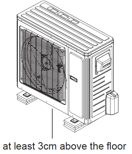
Outdoor unit
- The location should be well ventilated and dry so that the outdoor unit won’t be exposed directly to sunlight or strong wind.
- the location should be able to withstand the weight of the outdoor unit.
- Make sure that the installation follows the requirement of the installation dimension diagram.
- Select a location that is out of reach for children and far away from animals or plants. If it is unavoidable, please add the fence for safety purposes.
Requirements for electric connection
- Must follow the electric safety regulations when installing the unit.
- Make sure the power supply matches the requirement of the air conditioner. Unstable power supply or incorrect wiring or malfunction. Please install proper power supply cables before using the air conditioner.
- Properly connect the live wire, neutral wire, and grounding wire of the power socket.
- Be sure to cut off the power supply before proceeding with any work related to electricity and safety.
- If the supply cord is damaged, it must be replaced by the manufacturer, its
- The temperature of the refrigerant circuit will be high, please keep the interconnection cable away from the copper tube.
- The appliance shall be installed in accordance with national wiring regulations.
Grounding requirement
- The yellow-green wire in the air conditioner is a grounding wire, which can’t be used for other purposes.
- The grounding resistance should comply with national electric safety regulations.
- The appliance must be positioned so that the plug is accessible.
- An all-pole disconnection switch having a contact separation of at least 3mm in all poles should be connected to the fixed wiring.
- Including a circuit breaker with suitable capacity, please note the following table. The air switch should be included a magnet buckle and heating buckle function, it can protect the circuit from short and overload. (Caution: please do not use the fuse only to protect the circuit)
Installation of the outdoor unit
(select it according to the actual installation situation)
- Select installation location according to the house structure.
- Fix the support of the outdoor unit on the selected location with expansion screws.
- Make sure the support can withstand at least four times the unit weight.
- For the unit with a cooling capacity of 2300W ~5000W, 6 expansion screws are needed; for the unit with a cooling capacity of 6000W ~8000W, 8 expansion screws are needed; for the unit with a cooling capacity of 10000W ~16000W, 10 expansion screws are needed.
Step two: install drain joint Only for cooling and heating Unit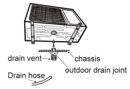
- connect the outdoor drain joint into the hole on the chassis, as shown in the picture below.
- Connect the drain hose to the drain vent.
Step Three fix the outdoor unit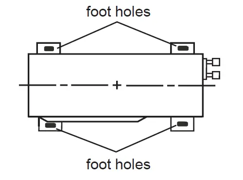
- Place the outdoor unit on the support.
- Fix the foot holes of the outdoor unit with bolts.
Step four: connect indoor and outdoor pipes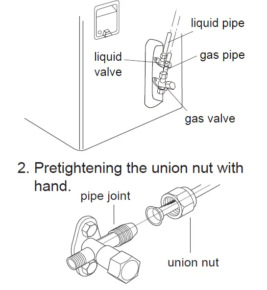
- Remove the screw cap of the valve and aim the pipe joint at the bellmouth of the pipe.
- Pretightening the union nut with hand.
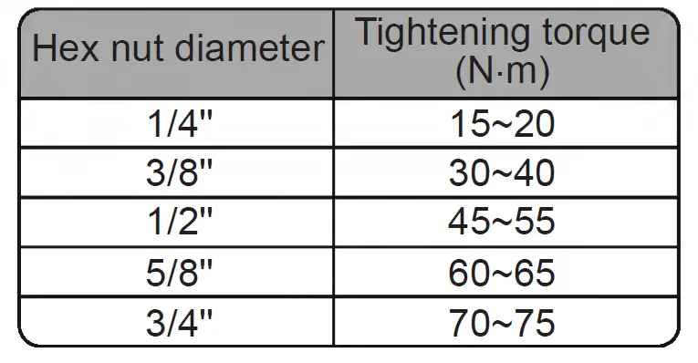
- Tighten the union nut with a torque wrench by referring to the sheet below.
Step Five: connect the outdoor electric wire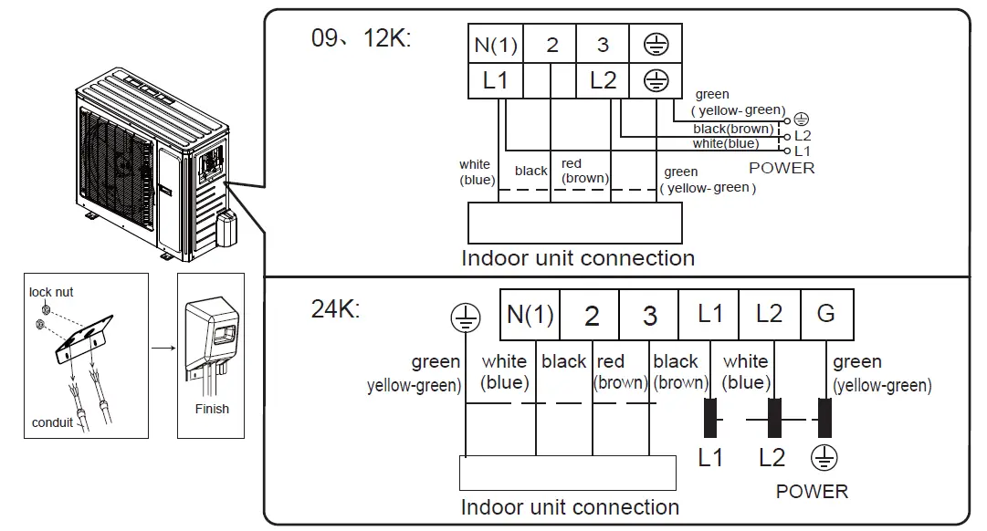
Remove the wire clip; connect the power connection wire and signal control wire (only for the cooling and heating unit) to the wiring terminal according to the color; fix them with screws.
Fix the power connection wire and signal control wire with a wire clip (only for the cooling and heating unit).
Note:
Never cut the power connection wire to prolong or shorten the distance.
Step six: neaten the pipes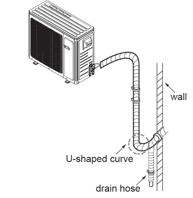
- The pipes should be placed along the wall, bent reasonably, and hidden possibly. Min. semidiameter of bending the pipe is 10cm.
- If the outdoor unit is higher than the wall hole, you must set a U-shaped curve in the pipe before the pipe goes into the room, in order to prevent rain from getting into the room.
Outdoor Condensate Drainage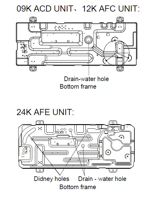
During heating operation, the condensate and defrosting water should be drained out reliably through the drain hose. Install the outdoor drain connector in a Φ25 hole on the base plate and attach the drain hose to the connector so that the wastewater formed in the outdoor unit can be drained out. The hole diameter of 25 must be plugged. Whether to plug other holes will be determined by the dealers to actual conditions. The 09K ACD UNIT、12K AFC UNIT、24K AFE UNIT drainage holes consist of two Φ25 and two kidney holes (see the fig.1). The drain plug consists of one Φ25 and two kidney plugs. (The figures in this manual may be different from the material objects, please refer to the material objects for reference)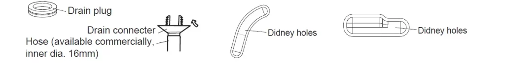
Vacuum pumping
Use vacuum pump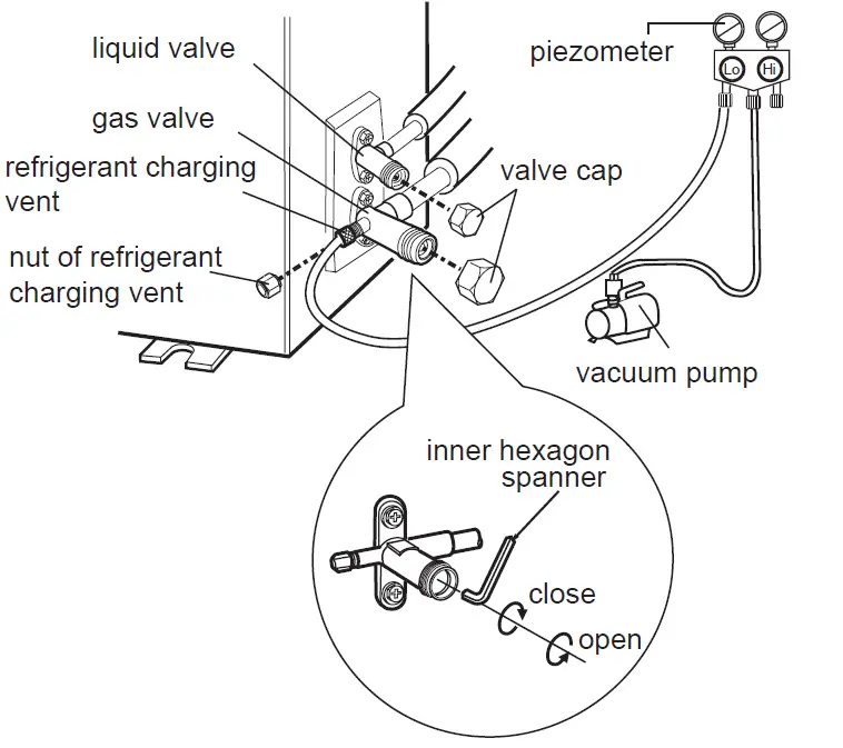
- Remove the valve caps on the liquid valve and gas valve and the nut of the refrigerant charging vent gerant charging vent.
- Connect the charging hose of the piezometer to the refri- gerant charging vent of the gas valve and then connect the other charging hose to the vacuum pump.
- Open the piezometer completely and operate for 10- 15min to check if the pressure of the piezometer re- mains is -0.1MPa.
- Close the vacuum pump and maintain this status for 1- 2min to check if the pressure of the piezometer remains in -0.1MPa. If the pressure decreases, there may be leakage.
- Remove the piezometer, open the valve core of the liquid valve and gas valve completely with an inner hexagon spanner.
- Tighten the screw caps of valves and refrigerant charging vent.
- Reinstall the handle.
Leakage detection
- With leakage detector: Check if there is leakage with the leakage detector.
- With soap water: If a leakage detector is not available, please use soap water for leakage detection. Apply soap water at the suspected position and keep the soap water for more than 3min. If there are air bubbles coming out of this position, there’s a leakage.
Check after installation
| Items to be checked | Possible malfunction |
| The unit may drop, shake or emit noise. | |
| Have you done the refrigerant leakage test? | (heating) capacity. |
| It may cause condensation and water dripping. | |
| Is water drained well? | It may cause condensation and water dripping. |
| Is the voltage of power supply accord- ing to the voltage marked on the nameplate? | It may cause malfunction or damaging the parts. |
| Is electric wiring and pipeline installed correctly? | It may cause malfunction or damaging the parts. |
| Is the unit grounded securely? | It may cause electric leakage. |
| Does the power cord follow the speci- | It may cause malfunction or damaging the parts. |
| Is there any obstruction in the air inlet and outlet? | (heating) capacity. |
| The dust and sundries caused during installation are removed? | It may cause malfunction or damaging the parts. |
| The gas valve and liquid valve of connection pipe are open completely? | (heating) capacity. |
| Is the inlet and outlet of piping hole been covered? | It may cause insufficient cooling (heating) capacity or waster eletricity. |
Test operation
Preparation of test operation
- The client approves the air conditioner.
- Specify the important notes for the air conditioner to the client.
Method of test operation
- Put through the power, press the ON/OFF button on the remote controller to start operation.
- Press the MODE button to select AUTO, COOL, DRY, FAN, and HEAT to check whether the operation is normal or not.
Configuration of the connection pipe
- The standard length of the connection pipe is 5m, 7.5m, 8m.
- Min. length of connection pipe is 3m.
- Max. length of connection pipe.
| Cooling capacity | Max length of connec- tion pipe |
| 5000Btu/h (1465W) | 15 |
| 7000Btu/h (2051W) | 15 |
| 9000Btu/h (2637W) | 15 |
| 12000Btu/h (3516W) | 20 |
| 18000Btu/h (5274W) | 25 |
| Cooling capacity | Max length of connec- tion pipe |
| 24000Btu/h (7032W) | 25 |
| 28000Btu/h (8204W) | 30 |
| 36000Btu/h (10548W) | 30 |
| 42000Btu/h (12306W) | 30 |
| 48000Btu/h (14064W) | 30 |
- The additional refrigerant oil and refrigerant charging are required after prolonging the connection pipe
- After the length of connection, the pipe is prolonged for 10m on the basis of standard length, you should add 5ml of refrigerant oil for each additional 5m of connection pipe.
- The calculation method of additional refrigerant charging amount (on the basis of liquid pipe):
- Additional refrigerant charging amount = prolonged length of liquid pipe × additional refrigerant charging amount per meter
- Basing on the length of the standard pipe, add refrigerant according to the requirement as shown in the table. The additional refrigerant charging amount per meter is different Additional refrigerant charging amount = prolonged length of liquid pipe × additional refrigerant charging amount per internet according to the diameter of the liquid pipe. See the following sheet.
Configuration of the connection pipe
| Piping size | Outdoor unit throttle | ||
| Liquid pipe | Gas pipe | Cooling only(g/m) | Cooling and heating(g/m) |
| 1/4” | 3/8” or 1/2” | 15 | 20 |
| 1/4” or 3/8” | 5/8” or 3/4” | 15 | 50 |
| 1/2” | 3/4” or 7/8” | 30 | 120 |
| 5/8” | 1” or 1 1/4” | 60 | 120 |
| 3/4” | _ | 250 | 250 |
| 7/8” | _ | 350 | 350 |
The additional refrigerant charging amount for R22, R407C, R410A and R134a
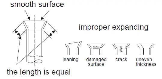
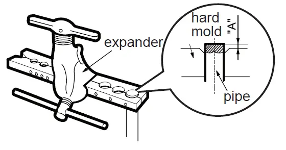
Pipe expanding method
NoteImproper pipe expansion is the main cause of refrigerant leakage. Please expand the pipe according to the following steps
- Cut the pipe the distance between the indoor unit and the outdoor unit. Cut the required pipe with a pipe cutter.
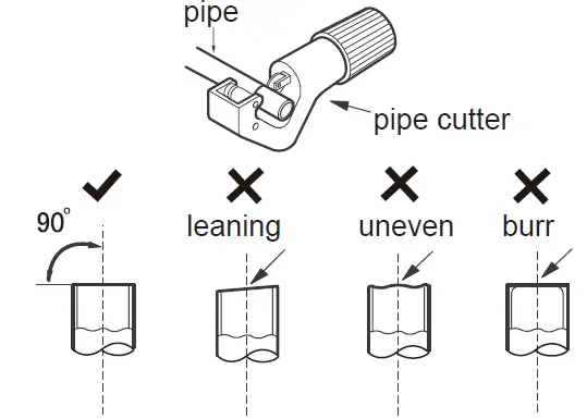
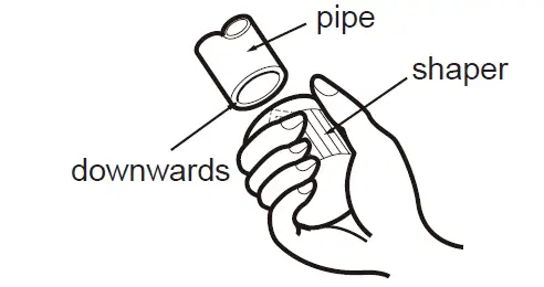
- Remove the burrs with a shaper and prevent the burrs from getting into the pipe.
- Put on suitable insulating pipe
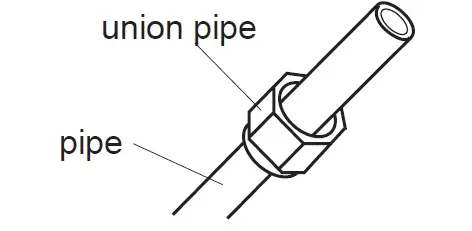
- Put on the union nut
- Expand the port
- Expand the port with an expander.
- Expand the port with an expander.
Note “A” is different according to the diameter, please refer to the sheet below
| Outer diameter (mm) | A(mm) | |
| Max | Min | |
| Φ6 – 6.35(1/4″) | 1.3 | 0.7 |
| Φ9 – 9.52(3/8″) | 1.6 | 1.0 |
| Φ12-12.7(1/2″) | 1.8 | 1.0 |
| Φ15.8-16(5/8″) | 2.4 | 2.2 |
- Inspection
Check the quality of expanding port. If there is any blemish, expand the port again according to the steps above.