BN-LINK FD60-U6 Dual Outlet Digital Timer
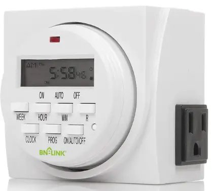
BN-LINK FD60-U6 Dual Outlet Digital Timer
PROGRAMING & SAFETY INSTRUCTIONS
- Rated Voltage: 115VAC, 60Hz
- Max.Load: 15A, 1725W
APPLICATIONS
- Lighting
- Cooling systems
- Humidifiers
- Heating systems
- Indoor sprinklers
- Nebullzers
- Aquariums
- Ventilators
WARNING
- Electrical shock hazard
- For indoor use only
- Use a grounded outlet
- Follow local electlical codes
- Do not exceed electrical ratings
INITIAL SETUP
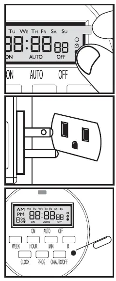
- Remove sticker
Locate the tab at the top right of the sticker and pull to remove sticker from face of screen. - Charge the internal batter
If the screen is blank, plug the timer into any outlet for 30 minutes to charge the internal battery. - Reset the timer
Press the “RESET” button with the tip of a small non-metallic insulated tool, such as a pencil or toothpick. LCD display will appear like this icon. - Unplug and program timer
Charging the battery allows the programming and setup of timer to occur from the comfort of your chair!
SET UP CURRENT DAY & TIME
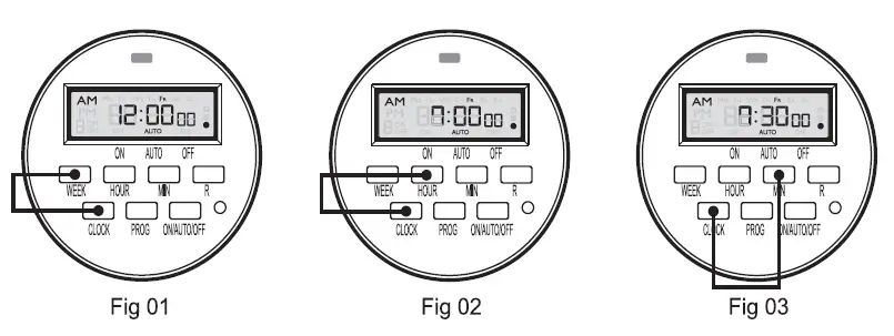
Example: if it is 7:30am Friday, please follow below steps to set the current day and time.
- Tap and hold the “CLOCK” button, then tap the “WEEK” button until “Fr” displays on top of the screen.
- Tap and hold the “CLOCK” button, then tap the “HOUR” button until 7:00am displays on the screen Note please pay attention to AM PM
- Tap and hold “CLOCK” button, and tap “MIN” button until 7:30am displays on the screen
SET PROGRAM
- Press the “PROG” button to enter the program setting, you will see the picture
Example: If you want to turn on a device every day at 8:05am and turn it off at 9:00pm, please follow below steps.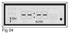
- Press the “WEEK” button to activate the desired days you would like your timer to operate. The most popular combinations will be programmed into the timer. If you do not see your desired days in any of the combinations. You will need to set multiple schedules into your programs to activate the days desired.
- MO to SU
- Individual day: MO,TU.WE,TH,FR,SA,SU
- MO to FR
- SA, SU
- MO to SA
- MO,WE, FR
- TU, TH, SA
- MO, TU, WE
- TH, FR, SA
- Press the “HOUR” button until 8:00am displays on the screen
- Press the “MIN” button until 8:05am displays on the screen
- Press the “PROG” button once to set program “1 OFF” you will see the picture
- Repeat steps 2 to 4 to set program “1 OFF”.
- If you want to set the second ON/OFF program, press “PROG” button again, you can repeat steps 2 to 6 to set program, or press the “CLOCK” button to save all your settings and take you back to your clock screen. Press “R” at any point to cancel the current setting. Press “R” again will take you back to the previous option.
- If you want to make the set of programs valid, please press “ON/AUTO/OFF” button to make sure the timer is in AUTO mode.
Attach up to TWO DEVICES to the timer
Plug the devices into the outlets on either side of the timer.
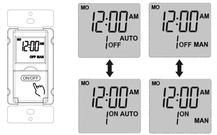
MANUAL OVERRIDE
Pressing ON/AUTO/OFF button can manually tum on and off the timer.
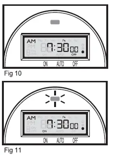
- OFF: Press ON/AUTO/OFF button until screen shows OFF. In this status, timer always has no output. The red LED output indicator on the top is off.
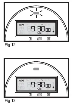
- ON: Press ON/AUTO/OFF button until screen shows ON. In this status, timer always has output. The red LED output indicator on the top is on.
Please set timer to AUTO status if you want to tum on and off automatically based on Programs you have set.
There are two AUTO status:
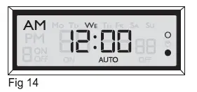
- AUTO ON: Press ON/AUTO/OFF button to the ON first, then press to the AUTO. It is ON status of the timer, top red LED indicator is ON, the timer will run the programs as previously set.
- AUTO OFF: Press ON/AUTO/OFF button
to the OFF first, then press to the AUTO. It is OFF status of the timer, top red LED indicator is OFF, then the timer will run the programs as previously set.
SET RANDOM FOR VACATION SECURITY
Pressing the “WEEK” and “HOUR” buttons simultaneously will activate security mode. “O” is to the right side of the display. When the timer is working in Auto mode and the random function is on, the previously programmed ON and OFF times will be separately postponed by 2-32 minutes. Press the “WEEK” and “HOUR” buttons again to tum off the Random function.
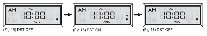
DST – DAYLIGHT SAVING TIME FUNCTION
Press HOUR & MIN simultaneously to activate or deactivate DST Note:A small clock symbol “(9″ will appear on the far right of the LCD screen when DST is active. It means manually add 1 hour to open the”Summer Time,” Otherwise it returns to current time
TROUBLESHOOTING
Timer does not turn on or off.
- Make sure AM and PM are correct on the current time and in the program settings.
- Timer program should be on AUTO setting.
- Make certain that both an ON and OFF time have been specified.
- If the number is not clear or blank on the screen, please plug the timer into any outlet for 30 minutes to charge the internal battery, then press the Reset button.
- The 2 grounded outlets are controlled by the same programs, they can not be set by different programs.
- If the timer can not Tum ON or Tum OFF on lime, please check if the Random function is in deactive status.
- If the timer always ON or always OFF, please check if the program is in Auto mode.
TIMER IS NOT WORKING ACCORDING TO YOUR PROGRAMS
WHATS GOING ON
If your AUTO setting is not activating your program because you have already past the start time. Please check the two different AUTO settings available to you and make sure you are choosing the correct AUTO status (ON to AUTO, or OFF to AUTO) Your ON/AUTO/OFF button has 4 different settings depending how many times you press the button. The 4 available operations are: [[ON]]-Manuallytuming ON your appliance (Your Appliance will ALWAYS BE ON in this state and will not run any timer programs.) [[OFF]] -Manually turning OFF your appliance ( Your Appliance will ALWAYS BE OFF in this state and will not run any timer programs.) [ION to AUTO]] start your selling on ON and finish the selling on AUTO Your appliance will tum on right when you plug the timer into a live wall outlet. Your appliance will stay on until 1st program ends and turns off accordingly to the timer. Schedule will run accordingly to the programs set. [[OFF to AUTO]] start your setting on OFF, and finish the setting on AUTO Your appliance will tum off right when you plug the timer into a live wall outlet, until the next program schedule and will run your program schedules accordingly. If you need more assistance, we have a helpful short instructional video most our customers find helpful. Please enter the model number provided on the back of your product to You Tube and you will find a helpful instructional video made by one of our technical support team members. (http://www.Youtube.com)
BN-LINK INC.
12991 Leffingwell Avenue, Santa Fe Springs Customer Service Assistance: 1.909.592.1881
E-mail: [email protected]
http://www.bn-link.com
Hours: 9AM – 5PM PST, Mon – Fri Designed in California Made in China
DOWNLOAD RESOURCES
- BN-LINK FD60-U6 Dual Outlet Digital Timer [pdf] User Manual FD60-U6, Dual Outlet Digital Timer, FD60-U6 Dual Outlet Digital Timer
- Read more: https://manuals.plus/bn-link/fd60-u6-dual-outlet-digital-timer-manual#ixzz7ogyFm9PI
FAQ’S
How do I program my BN Link dual outlet digital timer?
Function press the hour and minute buttons simultaneously to activate or deactivate the DST program and end an event press and release.
What app does BN Link use?
Yes, you can plug a power strip into a BN-Link Smart Plug and turn it on/off via the Century Smart app, Smart Life app or voice command with Amazon Echo/Google Assistant.
How do I change the time on my timer switch?
Off. Now you go on and off the set of pliers. Right loose there it’s loose then around here. And so I want to go off. Say. For other than air click turn your turn two are gonna work for anything.
How do you program a digital timer?
I’ll use the hour button to adjust the hour. The minute button to adjust a minute and the week key and you’ll see the week’s scroll across the top to select the day of the week.
How do I reset my BN Link timer?
Three prong electrical outlet to reset the timer. Press clock and program button at the same. Time. Press and hold a clock button then press the day button to set the day up to week
What is a 7 day timer?
Programmable 7 Day Timers. Programmable 7 Day Timers are compact digital time switches which provide precise timing with the flexibility of daily or weekly programming. Simple and fast setting by means of push buttons and display prompts.
Why is my digital timer not working?
CLEAN CONNECTORS IF NEEDED. DISCONNECT POWER FOR 30 SECONDS AND REAPPLY, SOMETIMES A POWER SURGE CAN LOCK UP THE ELECTRONICS AND THIS WILL RESET IT. IF YOU HAVE AN OLDER TIMER WITH AN INTERNAL BACK UP BATTERY IN IT THE BATTERY COULD BE WEAK OR DEAD.
Can you change the timer on motion sensor light?
Slide the “On-Time” switch to your preferred amount of minutes, such as one, five or 10 minutes. You may also program the motion sensor light settings from dusk to dawn as needed, or set them to stay illuminated for a certain timespan after dark if your device has a “Dual-Bright” setting.
What is a dual timer?
The Dual Timer has two timers which can be used separately or linked together (to give sequencing). The second timer can be used to give random timings instead of fixed timings if required. Each timer circuit switches relay contacts whilst timing.
How many modes are there in timer?
The timer registers can be used in two modes. These modes areTimer mode and the Counter mode. The only difference between these two modes is the source for incrementing the timer registers.
How do I use BN link dual outlet digital timer?
Button then tap the week button until the current day displays at the top of the screen repeat this process for both the hour.
Does bn link work with Alexa?
Smart WiFi Outlet Compatible with Alexa and Google Assistant 3-Pack BN-LINK.
VIDEO
BN-LINK FD60-U6 Dual Outlet Digital Timer
https://www.bn-link.com/
Instruction Manual

TECHNICAL SPECIFICATION
18 ON/OFF per day
With ON/OFF/Timing shift function
With Ni-MH recharging battery
Min. Setting time: 1 minute
Max. Setting time: 7 days
Supply voltage: 125V-,60Hz
Contact rating: 15A/1875W Resistive
10A/1250WTungsten, 10A/1250W Ballest,1/2 HP, TV-5
Do not exceed electrical ratings
Operating temperature: 5F 122F(-15€ 50C)
Storage temperature: -4F 140F (-20C 60C)
Insulation class: II
Protection class: IP20
Important: inductive (starting load) should always be calculated especially when controlling lighting (because of variable inductive loads).
If this load exceeds 8 Amps then it is imperative that a contractor be used.
PRODUCT QUICK GUIDE
Features
- The manual override button allows to turn on or off the timer at any time.
- Easy-to-read large LCD screen with clock display.
- Up to 18 ON events and 18 OFF events daily.
- Random security setting allows to respectively postpone ON and OFF times by 0-30 minutes to create a “lived-in” look.
- Turn on or off DTS with one simple push.
![]() WARNING
WARNING
- To prevent the risk of electric shock, cut off the power supply before installation.
- Always have a qualified electrician install this product.
INSTALLATION
STEP 1: CUT OFF THE POWER SUPPLY TO THE IN-WALL WIRING BOX.
STEP 2: REMOVE THE EXISTING DEVICE IF ANY.
STEP 3: INSTALL THE TIMER.
A. SINGLE-POLE INSTALLATION 
Note:
- To replace an existing switch, please make sure that the neutral wire is available in the wall box.
- Before wiring, please cut OFF the power at the breaker and switch the timer to MANUAL OFF. (Please refer to the chapter SWITCHING BETWEEN TWO OPERATION MODES)
- Wiring:
a. Ground wire: Connect the Ground wire in the wall box (or the earth screw) to the GREEN wire of the timer.
b. Neutral wire: Connect the Neutral wire in the wall box (from the breaker) to the WHITE wire of the timer. (The Neutral wire from the breaker should also be connected to the load’s neutral wire.)
c. Hotwire: Connect the hot wire in the wall box (from the breaker) to the BLACK wire of the timer.
d. Load wire: Connect the load’s hot wire (from load such as light) to the RED wire of the timer.
e. Use a wire nut to twist the BLUE wire for safety.
B. 3-WAY INSTALLATION
Conventional 3-way installation 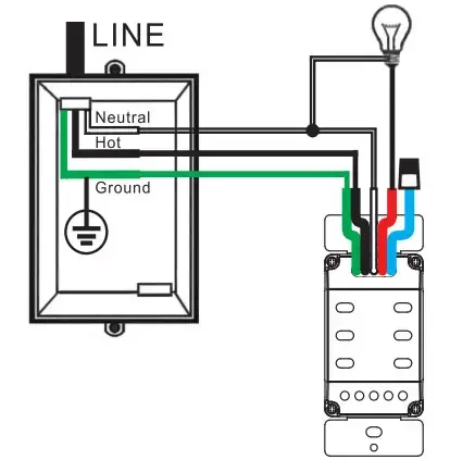
Timer-on-the-line-side installation
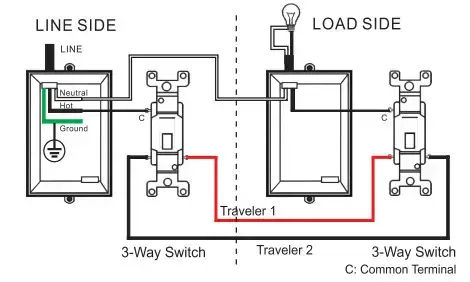
Note:
- To replace an existing switch, please make sure that the neutral wire is available in the wall box.
- Before wiring, please cut OFF the power at the breaker and switch the timer to MANUAL OFF. (Please refer to the chapter SWITCHING BETWEEN TWO OPERATION MODES)
- Wiring:
Step 1: Wring the LINE side
a. Ground wire: Connect the Ground wire in the wall box (or the earth screw) to the GREEN wire of the timer.
b. Neutral wire: Connect the Neutral wire in the wall box (from the breaker) to the WHITE wire of the timer. (The Neutral wire from the breaker should also be connected to the load’s neutral wire)
c. Hotwire: Connect the Hotwire in the wall box (from the breaker) to the BLACK wire of the timer.
d. Travelers:
Traveler 1: Connect Traveler 1( from the load side) to the RED wire of the timer.
Traveler 2: Connect Traveler 2 (from the load side) to the BLUE wire of the timer.
Step 2: Wring the LOAD side
Traveler 1: Connect Traveler 1 (from the timer) and load’s hot wire to the COMMON terminal (usually black or copper colored) of the 3-way switch.
Traveler 2: Connect Traveler 2 (from the timer) to either terminal (usually brass colored) of the 3-way switch.
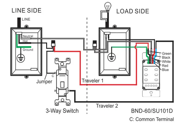
Timer-on-the-load-side installation 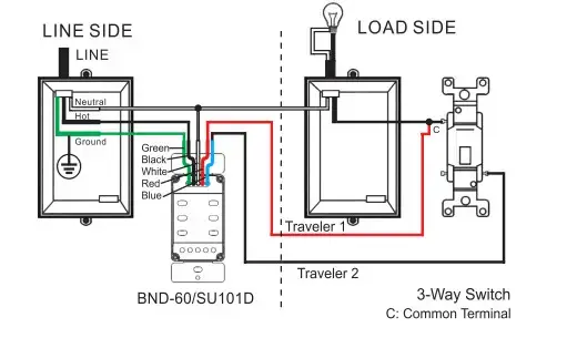
Note:
- To replace an existing switch, please make sure that the neutral wire is available in the wall box.
- Before wiring, please cut OFF the power at the breaker and switch the timer to MANUAL OFF. (Please refer to the chapter SWITCHING BETWEEN TWO OPERATION MODES)
- Wiring:
Step 1: Wring the LINE side
HOT wire: Connect the Hotwire in the wall box (from breaker) to Traveler 1 (from the timer) and the jumper, then connect the jumper to the COMMON terminal (usually black or copper colored) of the 3-way switch.
Traveler 2: Connect Traveler 2 (from the timer) to either terminal (usually brass colored) of the 3-way switch.
Step 2: Wring the LOAD side/TIMER
a. Ground wire: Connect the Ground wire in the wall box (or the earth screw) to the GREEN wire of the timer.
b. Neutral wire: Connect the Neutral wire in the wall box (from the breaker) to the WHITE wire of the timer. (The Neutral wire from the breaker should also be connected to the load’s neutral wire)
c. Load Hotwire: Connect the Load’s Hotwire in the wall box (from Load such as Light) to the RED wire of the timer.
d. Travelers:
Traveler 1: Connect Traveler 1 (From the LINE side) to the BLACK wire of the timer.
Traveler 2: Connect Traveler 2 (From the LINE side) to the BLUE wire of the timer.
C. 4-WAY INSTALLATION
 |
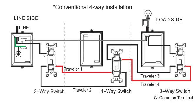 |
Note:
- To replace an existing switch, please make sure that the neutral wire is available in the wall box.
Also, make sure that 5 travelers are available between the wall boxes and mark each wire (such as “HOT WIRE, NEUTRAL WIRE, TRAVELER 1, TRAVELER 2 ..) for identification first, - Before wiring, please cut OFF the power at the breaker and switch the timer to MANUAL OFF. (Please refer to the chapter SWITCHING BETWEEN TWO OPERATION MODES)
- Wiring:
Step 1: Wring the LIND side/TIMER
a. Ground wire: Connect the Ground wire in the wall box (or the earth screw) to the GREEN wire of the timer.
b. Neutral wire: Connect the Neutral wire in the wall box (from the breaker) to the WHITE wire of the timer. (The Neutral wire from the breaker should also be connected to the load’s neutral wire)
c. Hotwire: Connect the Hotwire in the wall box (from the breaker) to the BLACK wire of the timer.
d. Travelers:
Traveler 1: Connect Traveler 1(from the 4-way switch box) to the BLUE wire of the timer.
Traveler 2: Connect Traveler 2(from the 4-way switch box) with the RED wire of the timer.
Step 2: Wring the 4-way switch
a. Traveler 1: Connect Traveler 1(from the LINE side) to any of the terminals of the 4-way switch.
b. Traveler 2: Connect Traveler 2(from the LINE side) to Traveler 5 (from the LOAD side).
c. Traveler 3: Connect Traveler 3(from the LOAD side) to one of the terminals at another end of the 4-way switch.
d. Traveler 4: Connect Traveler 4(from the LOAD side) to another terminal (at the same end as Traveler 3) of the 4-way switch.
ATTENTION: Traveler 1 can’t be connected to the terminal which is at the same end as Traveler 3 or Traveler 4. Traveler 3 and Traveler 4 to the 3-way switch fin the LOAD side) have to be connected at the same end.
Step 3: Wiring the LOAD side
a. Traveler 5: Use a wire nut to connect together the load’s hot wire, a jumper and Traveler 5(from the 4-way switch box), Then connect the jumper to the COMMON terminal (usually black or copper colored) of the 3-way switch on the LOAD side.
b. Traveler 3: Connect Traveler 3 (from the 4-way box side) to either terminal (usually brass colored) of the 3-way switch on the LOAD side.
c. Traveler 4: Connect Traveler 4 (from the 4-way box side) to the third terminal (usually brass colored) of the 3-way switch on the LOAD side.
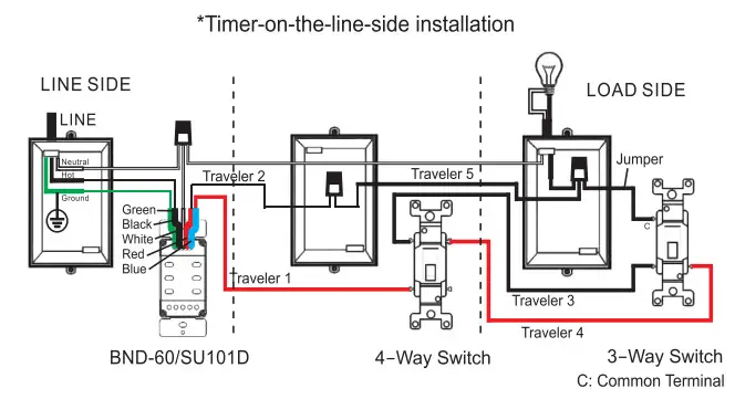
Note:
- To replace an existing switch, please make sure that the neutral wire is available in the wall box.
Also make sure that 7 travelers are available between the wall boxes and mark each wire (such as “HOT WIRE, NEUTRAL WIRE, TRAVELER 1, TRAVELER 2 …) for identification first. - Before wiring, please cut OFF the power at the breaker and switch the timer to MANUAL OFF. (Please refer to the chapter SWITCHING BETWEEN TWO OPERATION MODES)
- Wiring:
Step 1: Wiring the LINE side
a. HOT wire: Use a wire nut to connect together the HOT wire (from breaker), a jumper, and Traveler 5(from the 4-way switch box), then connect the jumper to the COMMON terminal (usually black or copper colored) of the 3-way switch on the LINE side.
b. Traveler 1: Connect Traveler 1 (from the 4-Way switch box/Timer) to either terminal (usually brass colored) of the 3-way switch on the LINE side.
c. Traveler 2: Connect Traveler 2(from the 4-Way switch box/Timer) to the third terminal (usually brass colored) of the 3-way switch on the LINE side.
Step 2: Wiring the 4-way switch /TIMER
a. Ground wire: Connect the Ground wire in the wall box (or the earth screw) to the GREEN wire of the timer.
b. Neutral wire: Connect the Neutral wire in the wall box (from the breaker) to the WHITE wire of the timer. (The Neutral wire from the breaker should also be connected to the load’s neutral wire)
c. Travelers:
Traveler 1: Connect Traveler1 (from the LINE side) to Traveler 4 (from the LOAD side).
Traveler 2: Connect Traveler2 (from the LINE side) to Traveler 3 (from the LOAD side).
Traveler 5: Connect Traveler 5(from the LINE side) to the BLACK wire of the timer.
Traveler 6: Connect Traveler 6(from the LOAD side) to the BLUE wire of the timer.
Traveler 7: Connect Traveler 7(from the LOAD side) to the RED wire of the timer.
Step 3: Wiring the LOAD side
a. Traveler 6: Connect Traveler 6(from the TIMER) to COMMON terminal usually black or copper colored) of the 3-way switch on the LOAD side.
b. Traveler 3: Connect Traveler 3(from the TIMER) to either terminal (usually brass colored) of the 3-way switch on the LOAD side.
c. Traveler 4: Connect Traveler 4 (from the TIMER) to the third terminal (usually brass colored) of the 3-way switch on the LOAD side.
d. Traveler 7: Connect Traveler 7(from the TIMER) to the load’s hot wire.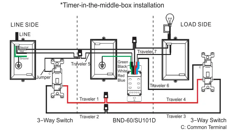
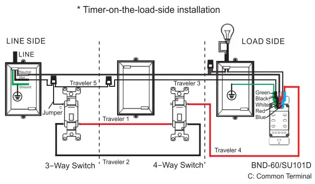
Note:
- To replace an existing switch, please make sure that the neutral wire is available in the wall box.
Also, make sure that 5 travelers are available between the wall boxes and mark each wire (such as “HOT WIRE, NEUTRAL WIRE. TRAVELER 1, TRAVELER 2..) for identification first. - Before wiring, please cut OFF the power at the breaker and switch the timer to MANUAL OFF. (Please refer to the chapter SWITCHING BETWEEN TWO OPERATION MODES)
- Wiring:
Step 1: Wiring the LINE side
a. Use a wire nut to connect together the HOT wire (from breaker), a jumper, and Traveler 5(from the 4-way switch box), then connect the jumper to the COMMON terminal (usually black or copper colored) of the 3-way switch on the LINE side.
b. Traveler 1: Connect Traveler 1(from the 4-Way switch box) to either terminal (usually brass colored) of the 3-way switch on the LINE side.
c. Traveler 2: Connect Traveler 2(from the 4-Way switch box) to the third terminal (usually brass colored) of the 3-way switch on the LINE side.
Step 2: Wring the 4-Way switch
a. Traveler 1: Connect Traveler 1 (from the LINE side) to any terminal of the 4-way switch.
b. Traveler 2: Connect Traveler 2(from the LINE side) to the terminal (at the same end of Traveler 1) of the 4-way switch.
c. Traveler 4: Connect Traveler 4(from the LOAD side) to the third terminal (at another end) of the 4-way switch.
d. Traveler 5: Connect Traveler 5(from the LINE side) to Traveler 3(from the LOAD side).
Step 3: Wring the LOAD side/TIMER
a. Ground wire: Connect the Ground wire in the wall box (or the earth screw) to the GREEN wire of the timer.
b. Neutral wire: Connect the Neutral wire in the wall box (from the breaker) to the WHITE wire of the timer. (The Neutral wire from the breaker should also be connected to the load’s neutral wire)
c. Load Hotwire: Connect the Load’s Hotwire in the wall box (from Load such as Light) to the RED wire of the timer.
d. Travelers:
Traveler 3: Connect Traveler 3 (from the 4-way switch) to the BLACK wire of the timer.
Traveler 4: Connect Traveler 4 (from the 4-way switch) to the BLUE wire of the timer.
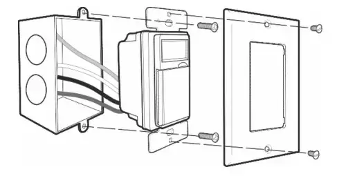
STEP 4: FIX THE TIMER TO THE WIRING BOX AND THEN MOUNT THE FACE PLATE.
STEP 5: APPLY POWDER TO THE WIRING BOX.
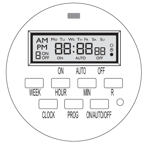
BUTTON LAYOUT AND SCREEN DISPLAY
REMOVE STICKER
Locate the tab at the top right of the sticker and pull to remove the sticker from the face of the screen. 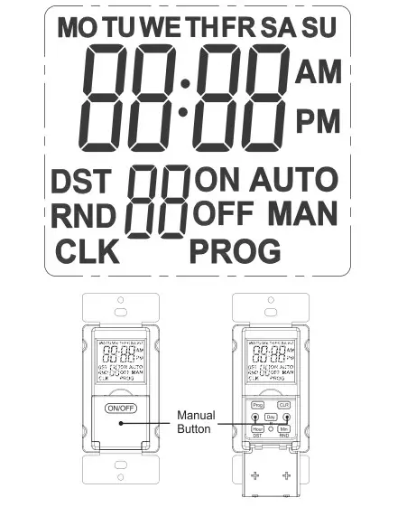
RESTING THE TIMER
If the screen display is blank or faded, you can charge the battery for 10 minutes and then press the “RESET” button to reset the system. When the system is initialized, the screen display will be flashing. The LCD display will appear like this icon. Press any button at this time or wait ‘ 2 minutes without any operation, the clock will display.
Note: The system time and all settings will be erased after the system reset. 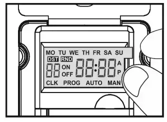
SETTING THE SYSTEM TIME
Example: if it is 12:08 am Monday. please follow the below steps to set the current day and time.
- Press the “PROG” button, then press the “DAY” button until “MO” displays on top of the screen. (Fig 01)
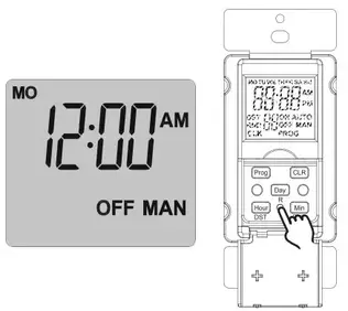
- Then press the “HOUR” button until 12:00 am displays on the screen.
(Fig 02)
Note: please pay attention to AM/PM. - Then press the “MIN” button until 12:08 am displays on the screen.
(Fig 03)
Note: When the current time is correctly set, press the “MANUAL” button to save and quit the clock display screen; or press “PROG” to start setting the programs.
If no button is pressed within 6 seconds, the timer will automatically save the current time and return to the clock display screen.
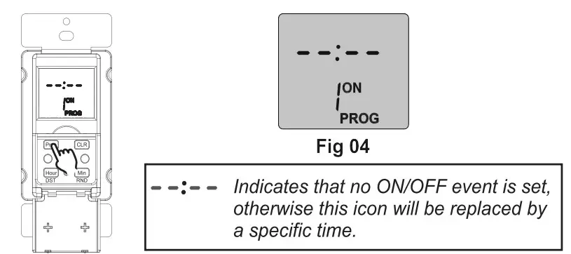
SETTING THE PROGRAM
- To start programming ON/OFF events, press “PROG” once during the system clock setting stage or press PROG twice on the clock display screen.
The screen will display “1 ON” and “PROG. (Fig 04)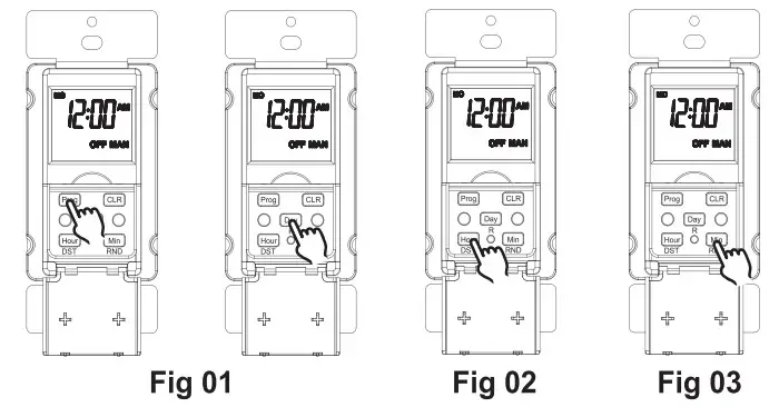
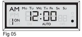
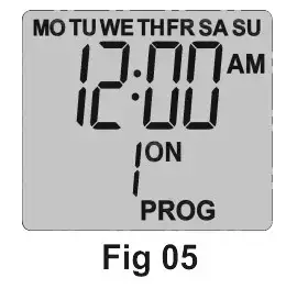
For example: if you want to turn on a device every day at 8:05 am and turn it off at 9:00 pm, please follow the below steps. - 2. Press the “DAY” button to enter the program setting, you will see all the days of the week on the top and “1 ON” to the left of the display. (Fig 05)
Note Press “DAY” multiple times until you get the day combination you want.
 Day combination options:
MO to SU
Individual day: MO,TU,WE,TH,FR,SA,SU
MO to FR
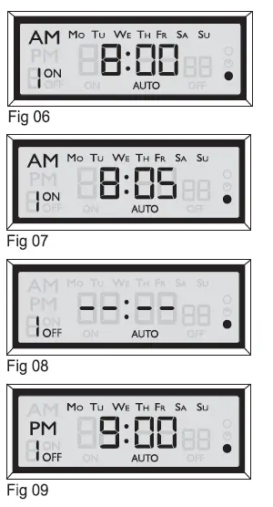
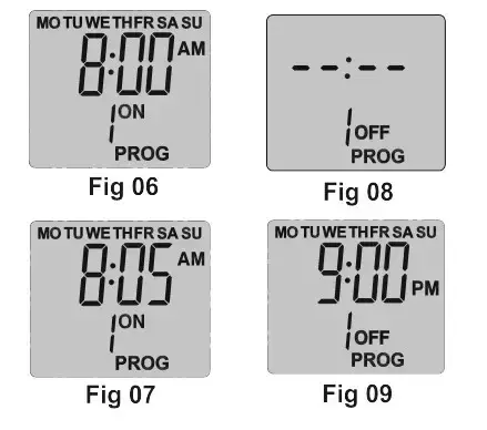
SA, SU - Press the “HOUR” button until 8:00 am displays on the screen. (Fig 06)
Note: please pay attention to AM/PM. - Press the “MIN” button until 8:05 am displays on the screen. (Fig 07)
- Press the “PROG” button once to set the program “1 OFF”. The screen will display “1 OFF” and “PROG.(Fig 08)
- Repeat steps 2 to 4 to set program “1 OFF. (Fig 09)
- If you want to set the second ON/OFF program, press the “PROG” button again, you can repeat steps 2 to 6 to set the program, or press the “MANUAL” to return the current time. You can set up to 18 different ON and OFF programs for your timer. To do so, just repeat steps 1 to 6 for the program “2 ON” “2 OFF” “3 ON” etc…
- During the programming process, you can clear the previous settings by pressing the “CLR” button. Pressing the “CLR” a second time will resume the previous settings.
- When all ON/OFF events are programmed, press the “MANUAL” button to return to the clock display screen.
If no button is pressed within 6 seconds, the timer will automatically save the settings and return to the clock display screen.
You can review, change or delete any event in the same way you program an event. - Press and hold the “MANUAL” button till the AUTO icon is shown so that the timer will run the programs.
SWITCHING BETWEEN TWO OPERATION MODES
The timer can work in two different operating modes: AUTO and MANUAL.
They are represented by icons AUTO and MAN on the screen. Press and hold the “MANUAL” button for 4 seconds or longer to switch between these two operating modes. In either operation mode, you can press the “MANUAL” button to alter the timer’s output status.
SWITCHING ON/OF DST
DST is active when the DST icon is shown on the screen.
RANDOM SECURITY
To activate or deactivate the random security feature, press and hold the “Min” button for 4 seconds or more.
The “RND” icon on the screen indicates that the random function is active.
In this case, the timer will respectively postpone the ON and OFF events by 0-30 minutes. Please note that at least one ON/OFF program shall be set to activate this feature. 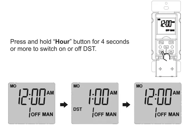
SCREEN BACKLIGHT
Press any button to turn on the backlight.
On the clock display screen, the backlight will go out after 5 seconds without any button operation.
When you are setting the system time or programs, the backlight will go out after 90 seconds without any button operation.
TROUBLESHOOTING
PROBLEM:
The timer does not turn on or off as programmed.
- POSSIBLE CAUSE:
Programs were not correctly set.
DST or random function is active.
The timer is working in manual mode.
Programs are overlapped. - CORRECTIVE ACTION:
Re-program the timer following the operating instructions.
Deactivate DST or random function.
Switch the operation mode to AUTO.
Review and correct the programs or re-program the timer.
PROBLEM:
No screen display or faded display.
- POSSIBLE CAUSE:
Low battery. - CORRECTIVE ACTION:
Energize the timer to charge the internal battery for 10 minutes and then press the RESET button to reset the timer.
Please keep this handbook
BN-LINK INC.
12991 Leffingwell Avenue, Santa Fe Springs
Customer Service Assistance: 1.909.592.1881
E-mail: [email protected]
http://www.bn-link.com
Hours: 9 AM – 5 PM PST, Mon – Fri
Designed in California and Made in China