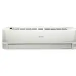
40MAHB
Ductless Split Unit System
Sizes 9, 12, 18, 24, 30 and 36
Installation Instructions
NOTE: Read the entire instruction manual before starting the installation.
Images are for illustration purposes only. Actual models may differ slightly.
SAFETY CONSIDERATIONS
Improper installation, adjustment, alteration, service, maintenance, or use can cause an explosion, fire, electrical shock, or other conditions which may cause death, personal injury, or property damage. Consult a qualified installer, service agency, or your distributor or branch for information or assistance. The qualified installer or agency must use factory-authorized kits or accessories when modifying this product. Refer to the individual instructions packaged with kits or accessories when installing.
Follow all safety codes. Wear safety glasses, protective clothing, and work gloves. Have a fire extinguisher available. Read these instructions thoroughly and follow all warnings or cautions included in the literature and attached to the unit. Consult local building codes and the current editions of the National Electrical Code (NEC) NFPA 70.
In Canada, refer to the current editions of the Canadian Electrical Code CSA C22.1. Recognize safety information. This is the safety alert symbol. When you see this symbol on the unit and in instruction manuals, be alert to the potential for personal injury. Understand the signal words DANGER, WARNING, and CAUTION. These words are used with the safety alert symbol. DANGER identifies the most serious hazards which will result in severe personal injury or death.
WARNING signifies hazards that could result in personal injury or death.
 CAUTION is used to identify unsafe practices which may result in minor personal injury or product and property damage. NOTE is used to highlight suggestions that will result in enhanced installation, reliability, or operation.
WARNING
ELECTRICAL SHOCK HAZARD
Failure to follow this warning could result in personal injury or death. Before installing, modifying, or servicing the system, the main electrical disconnect switch must be in the OFF position. There may be more than 1 disconnect switch. Lockout and tag switch with a suitable warning label.
WARNING
EXPLOSION HAZARD
 Failure to follow this warning could result in death, serious personal injury, and/or property damage.
Never use air or gases containing oxygen for leak testing or operating refrigerant compressors. Pressurized mixtures of air or gases containing oxygen can lead to an explosion.
CAUTION
EQUIPMENT DAMAGE HAZARD
Failure to follow this caution may result in equipment damage or improper operation.
Do not bury more than 36 in. (914 mm) of refrigerant pipe in the ground. If any section of pipe is buried, there must be a 6 in. (152 mm) vertical rise to the valve connections on the outdoor units. If more than the recommended length is buried, the refrigerant may migrate to the cooler buried section during extended periods of system shutdown. This causes refrigerant slugging and could possibly damage the compressor at start-up.
ACCESSORIES
The system is shipped with the following accessories (see Table 1). Use all of the installation parts and accessories to install the system. Improper installation may result in water leakage, electrical shock and fire, or cause the equipment to fail. Keep the installation manual in a safe place and do not discard any other accessories until the installation work has been completed.
Table 1 — Accessories
| NAME | SHAPE | QUANTITY |
| Installation Manual |  |
2-3 |
| Drain Joint | 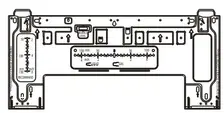 |
1 |
| Seal (for cooling and heating models) |
 |
1 |
| Mounting Plate | 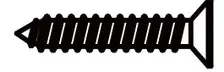 |
1 |
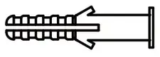
| Anchor |  |
5-8 (depending on models) |
| Mounting Plate Screw |
 |
5-8 (depending on models) |
| Remote Controller |  |
1 |
| Battery |  |
2 |
| Remote Controller Holder (optional) |
 |
1 |
| Remote Controller Holder Screw (optional) |
 |
2 |
| Small Filter (Must be installed on the back of the main air fitter by an authorized technician during unit installation) |
 |
1-2 depending on the model |
Table 2 — Accessories
| NAME | SHAPE | QUANTITY (PC) | |
| Connecting Pipe Assembly |
Liquid Side |
1/4in(cD 6.35) | These parts must be purchased separately. Consult the dealer about the proper pipe size of the unit purchased. |
| 3/8in (0 9.52) | |||
| Gas Side | 3/8in (0 9.52) | ||
| 1/2in (012.7) | |||
| 5/8in (016) | |||
| 3/4in (019) | |||
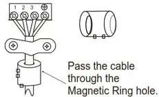
| Magnetic Ring and Clamp (if supplied refer to the wiring diagram to install it to the cable. |  |
Varies by model | |
PARTS

NOTE: Illustrations in this manual are for reference only. The actual shape of the indoor unit and parts may differ slightly.
- Wall Mounting Plate
- Front Panel
- Louver
- Air Filter
- Drainage Pipe
- Signal Cable
- Refrigerant Piping
- Remote Controller
- Remote Controller Holder (some units)
- Outdoor Unit Power Cable (some units)
NOTES:
– If the outdoor unit is higher than the indoor unit, prevent rain from flowing into the indoor unit along the connection pipe by making an inverted trap in the connection pipe before it enters the wall to the indoor unit. This ensures that rain drips from the connection pipe before it enters the wall.
– Piping and the interconnecting wiring are field supplied.
– The illustration above (Fig. 2) is only a sketch. Different models may differ slightly.
The units listed in Table 3 are addressed in these installation instructions.
Table 3 — Indoor Units
| DESCRIPTION | BTUH | V-PH-HZ | ID MODEL NO. |
| 12 | 115-1-60 | 40MAHBQ12XA1 | |
| HIGH WALL HEAT PUMP |
9 | 208 230-1-60 | 40MAHBQ09XA3 |
| 12 | 40MAHBQ12XA3 | ||
| 18 | 40MAHBQ18XA3 | ||
| 24 | 40MAHBQ24XA3 | ||
| 30 | 40MAHBQ3OXA3 | ||
| 36 | 40MAHBQ36XA3 |
NOTE: The installation must be performed in accordance with the requirement of local and national standards. The installation may differ slightly in some areas.
NOTE: Different models have different front panels and display windows.
SYSTEM REQUIREMENTS
Allow sufficient space for airflow and unit service. Fig. 5 — on page 7 for the minimum required distances between the unit and walls or ceilings.
Table 4 — Indoor Unit Pipe Sizes
| UNIT SIZES | 12K (115V) |
9K (208/230V) |
12K (208/230V) |
18K (208/230V) |
24K (208/230V) |
30K (208/230V) |
36K (208/230V) |
|
| GAS PIPE | in | 0.5 | 0.375 | 0.5 | 0.5 | 0.626 | 0.626 | 0.626 |
| (mm) | 13. | (10.) | 13. | 13. | 16. | 16. | 16. | |
| LIQUID PIPE | in | 0.25 | 0.25 | 0.25 | 0.25 | 0.375 | 0.375 | 0.375 |
| (mm) | 25 | 25 | 25 | 25 | 10. | 10. | 10. | |
WIRING
All wires must be sized per NEC (National Electrical Code) or CEC (Canadian Electrical Code) and local codes. See the rating plate and/ or the installation instructions of the compatible outdoor unit for MCA (minimum circuit amps) and MOCP (maximum overcurrent protection) to correctly size the wires and the disconnect fuse or breakers respectively.
Recommended Connection Method for Power and Communication Wiring:
The main power is supplied to the outdoor unit. The field supplied 14/ 3 power/communication wiring from the outdoor unit to the indoor unit consisting of four (4) wires and provides the power for the indoor unit. Two wires are high voltage AC power, one is communication wiring and the other is a ground wire. Wiring between the indoor and outdoor unit is polarity sensitive. The use of BX wire is NOT recommended.
If installed in a high Electromagnetic field (EMF) area and communication issues exist, a 14/2 stranded shielded wire can be used to replace L2/N and (S) between outdoor unit and indoor unit landing the shield onto the ground in the outdoor unit only.
WARNING
EQUIPMENT DAMAGE HAZARD
Failure to follow this caution may result in equipment damage or improper operation.
Wires should be sized based on NEC and local codes.
CAUTION
EQUIPMENT DAMAGE HAZARD
Failure to follow this caution may result in equipment damage or improper operation.
Be sure to comply with local codes while running a wire from the indoor unit to the outdoor unit.
Every wire must be connected firmly. Loose wiring may cause the terminal to overheat or result in unit malfunction. A fire hazard may also exist. Ensure all wiring is tightly connected.
No wire should touch the refrigerant tubing, compressor or any moving parts.
Disconnecting means must be provided and shall be located within sight and readily accessible from the air conditioner. Connecting cable with conduit shall be routed through the hole in the conduit panel.
NOTE: The main power is supplied to the outdoor unit. When disconnecting the power of the outdoor unit, the indoor unit would lose power. A disconnect switch is not required on the Indoor unit side on the wiring between the Outdoor and Indoor
unit. A 3 pole disconnect may be used for extra protection between the Indoor and Outdoor units.
DIMENSIONS
| HIGH WALL UNIT SIZE | 12K | 9K | 12K | 18K | 24K | 30K | 36K | |
| (Voltage) | (115V) | (208/230V) | (208/230V) | (208/230V) | (208/230V) | (208/230V) | (208/230V) | |
| DIMENSIONS | ||||||||
| Height (H) | In (mm) | 11.61 (295) | 11.61 (295) | 11.61 (295) | 12.56 (319) | 14.57 (370) | 14.57 (370) | 14.57 (370) |
| Width (W) | In (mm) | 31.3 (795) | 31.3 (795) | 31.3 (795) | 37.99 (965) | 44.88 (1140) | 44.88 (1140) | 44.88 (1140) |
| Depth (D) | In (mm) | 8.86 (225) | 8.86 (225) | 8.86 (225) | 9.41 (239) | 10.83 (275) | 10.83 (275) | 10.83 (275) |
| PACKING | ||||||||
| Height (H) | In (mm) | 12.01 (305) | 12.01 (305) | 12.01 (305) | 12.80 (325) | 13.98 (355) | 13.98 (355) | 13.98 (355) |
| Width (W) | In (mm) | 34.25 (870) | 34.25 (870) | 34.25 (870) | 41.14 (1045) | 48.43 (1230) | 48.43 (1230) | 48.43 (1230) |
| Depth (D) | In (mm) | 14.57 (370) | 14.57 (370) | 14.57 (370) | 15.75 (400) | 17.91 (455) | 17.91 (455) | 17.91 (455) |
| Thickness | In (mm) | 0.295 (7.5) | 0.295 (7.5) | 0.295 (7.5) | 0.295 (7.5) | 0.295 (7.5) | 0.295 (7.5) | 0.295 (7.5) |
| Weight – Gross | lbs. (kg) | 29.10 (13.2) | 28.88 (13.1) | 28.88 (13.1) | 35.71 (16.2) | 54.89 (24.9) | 54.89 (24.9) | 54.89 (24.9) |
| Weight – Net | lbs. (kg) | 22.93 (10.4) | 22.71(10.3) | 22.71(10.3) | 27.12 (12.3) | 43.65 (19.8) | 43.65 (19.8) | 43.65 (19.8) |
CLEARANCES
![]()
NOTE: The top clearance recommended for proper return airflow is 5.9in (15cm). Reduction of this clearance may decrease unit performance. This may be reduced to 3.2in (80mm) as long as the right and left clearances are achieved.
PRIOR TO INSTALLATION
Before installing the indoor unit, ensure compatibility with the outdoor unit using the product data as a reference. It is also necessary to confirm the proper application of the equipment and to perform a heat load calculation for proper sizing.
Step 1 – Check Equipment
Unpack the unit and move to the final location. Remove the carton, taking care not to damage the unit. Inspect the equipment for damage prior to installation. File a claim with the shipping company if the shipment is damaged or incomplete. Locate the unit rating plate, which contains the proper installation information. Check the rating plate to be sure the unit matches the job specifications.
The indoor unit should be installed in a location that meets the following requirements:
- Enough room for installation and maintenance
- Enough room for the lines and drainpipe
- A horizontal ceiling and a structure that can sustain the weight of the indoor unit
- The air inlet and outlet are not impeded
CAUTION
DO NOT install the unit in the following locations:
- Areas with oil drilling or fracking
- Coastal areas with high salt content in the air
- Areas with caustic gases in the air, such as near hot springs
- Areas with power fluctuations, such as factories
- Enclosed spaces, such as cabinets
- Areas with strong electromagnetic waves
- Areas that store flammable materials or gas
- Rooms with high humidity, such as bathrooms or laundry rooms.
WARNING
PRODUCT INSTALLATION
- Installation must be performed by an authorized dealer or specialist. A defective installation can cause water leakage, electrical shock, or fire.
- The installation must be performed according to the installation instructions. Improper installation can cause water leakage, electrical shock, or fire. (In North America, installation must be performed in accordance with the requirements of NEC or CEC by authorized personnel only.)
- Contact an authorized service technician for repair or maintenance of this unit. This appliance must be installed in accordance with local codes.
- Only use the included accessories, parts, and specified parts for installation. Using non-standard parts can cause water leakage, electrical shock, fire, or unit failure.
- Install drainage piping according to the instructions in this manual.
Improper drainage may cause water damage to your home and property. - For units that have an auxiliary electric heater, DO NOT install the unit within 3 feet (1 meter) of any combustible materials.
- DO NOT install the unit in a location that may be exposed to combustible gas leaks. If combustible gas accumulates around the unit, it may cause a fire.
- DO NOT turn on the power until all work has been completed.
- When moving or relocating the system, consult experienced service technicians for the disconnection and reinstallation of the unit.
Step 2 – Select the Installation Location
Before installing the indoor unit, choose an appropriate location.
The following are standards that should help you choose an appropriate location for the unit.
Proper installation locations must meet the following standards:
- Good air circulation
- Convenient drainage
- Noise from the unit will not disturb others
- Firm and solid—the location will not vibrate
- A location at least 3.28 ft. (1m) from all other electrical devices
(e.g., TV, radio, computer) - DO NOT install the unit in the following locations:
a. Near any source of heat, steam, or combustible gas
b. Near flammable items such as curtains or clothing
c. Near any obstacle that might block air circulation
d. Near the doorway
e. In a location subject to direct sunlight
NOTE: When selecting a location leave ample room for a wall hole (refer to the drill wall hole for connective piping step) for the signal cable and refrigerant piping that connect the indoor and outdoor units. The default position for all piping is the right side of the indoor unit (while facing the unit). However, the unit can accommodate piping to either left or right.
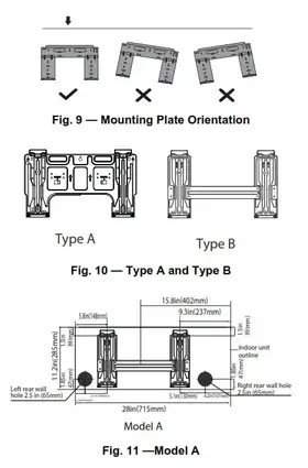
Step 3 – Attach the Mounting Plate to the Wall
Use the following steps to attach the mounting plate to the wall.
- Carefully remove the mounting plate, which is attached to the back of the indoor unit.
- The mounting plate should be located horizontally and at the level on the wall. All minimum spacings should be maintained.
- If the wall is the block, brick, concrete or similar material, drill 0.2in (5 mm) diameter holes and inserts anchors for the appropriate mounting screws.
- Attach the mounting plate.
- Drill holes in the wall:

a. If the wall is brick, concrete or of similar material, drill a 5mm-diameter (0.2in-diameter) hole into the wall and insert the sleeve anchors provided.
b. Next, secure the mounting plate to the wall by tightening the screws directly into the clip anchors.
Step 4 – Drill Wall Holes for Connective Piping
- Determine the location of the wall hole based on the position of the mounting plate. Refer to the Mounting Plate Dimensions.
- Use a 2.5in (65mm) or 3.54in (90mm) (depending on models) core drill to drill a hole in the wall. Make sure that the hole is drilled at a slightly downward angle so the outdoor end of the hole is lower than the indoor end by about 0.2 – 0.275in (5 – 7mm). This ensures proper water drainage.
- Place the protective wall cuff in the hole. This protects the edges of the hole and helps to seal it once the installation is complete.
Mounting Plate Dimensions
Different model sizes have different mounting plates. Ensure there is enough room to mount the indoor unit (refer to Figures 11−14). The following measurements can be located on these figures:
- Width of the mounting plate
- Height of mounting plate
- Width of the indoor unit relative to plate
- Height of indoor unit relative to the plate
- The recommended position of wall hole (both to the left and right of mounting plate)
- Relative distances between screw holes.
 |
 |
NOTE: When the gas side connective pipe is 5/8in (16mmΦ) or more, the wall hole should be 3.54in (90mm).
DRILL A HOLE IN THE WALL FOR THE
INTERCONNECTING PIPING, DRAIN, AND WIRING
Refrigerant Line Routing
The refrigerant lines may be routed in any of the four directions. For maximum serviceability, it is recommended to have refrigerant line flare connections and the drain connections on the outside of the wall that the fan coil can be mounted on. If piping is going through the back, determine the pipe hole position using the mounting plate as a template. Drill pipe hole diameter per values given in figures 11 through 14. The outside pipe hole is 1/2−in. (13 mm) min. lower than the inside pipe hole, so it slants slightly downward.
Step 4 – Prepare Refrigerant Piping
The refrigerant piping is inside an insulating sleeve attached to the back of the unit. The installer must prepare the piping before passing it through the hole in the wall.
- Based on the position of the wall hole relative to the mounting plate, choose the side from which the piping exits the unit.
- If the wall hole is behind the unit, keep the knock-out panel in place. If the wall hole is to the side of the indoor unit, remove the plastic knock-out panel from that side of the unit. This creates a slot through which your piping can exit the unit. Use needle-nose pliers if the plastic panel is too difficult to remove by hand.

- If the existing connective piping is already embedded in the wall, proceed directly to “Step 5 – Connect the Drain Hose”. If there is no embedded piping, connect the indoor unit’s refrigerant piping to the connective piping that connects the indoor and outdoor units.

NOTE: Refrigerant piping can exit the indoor unit from four different angles; left-hand side, right-hand side, left rear, right rear.
CAUTION
Be extremely careful not to dent or damage the piping while bending them away from the unit. Any dents in the piping will affect the unit’s performance.
Step 5 – Connect the Drain Hose
By default, the drain hose is attached to the left-hand side of the unit (when you are facing the back of the unit). However, it can also be attached to the right-hand side. To ensure proper drainage, attach the drain hose on the same side that your refrigerant piping exits the unit. Attach a drain hose extension (purchased separately) to the end of the drain hose.
- Wrap the connection point firmly with Teflon tape to ensure a good seal and to prevent leaks.
- For the portion of the drain hose that remains indoors, wrap it with foam pipe insulation to prevent condensation.
- Remove the air filter and pour a small amount of water into the drain pan to ensure that water flows smoothly from the unit.
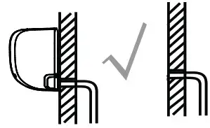
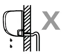
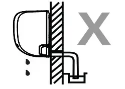
NOTE: Be sure to arrange the drain hose according to Figure 17.
CORRECT
Ensure there are no kinks or dents in the drain hose to ensure proper drainage.
NOT CORRECT
Ensure there are no kinks or dents in the drain hose to ensure proper drainage.
NOT CORRECT
Kinks in the drain hose create water traps. 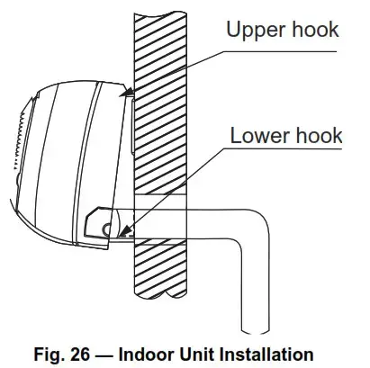
NOT CORRECT
Do not place the end of the drain hose in water or in containers that collect water. This prevents proper drainage.
Fig. 17 — Drain Hose Placement
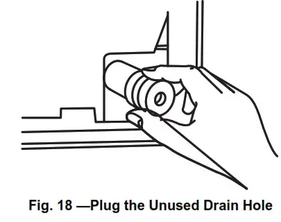
Plug the Unused Drain Hole
To prevent unwanted leaks, plug the unused drain hole with the rubber plug provided.
CAUTION
All wiring must comply with local and national electrical codes, regulations and must be installed by a licensed electrician. All electrical connections must be made according to the Electrical Connection Diagram located on the panels of the indoor and outdoor units.
If there is a serious safety issue with the power supply, stop work immediately. Explain your reasoning to the client, and refuse to
install the unit until the safety issue is properly resolved.
Power voltage should be within 90-110% of rated voltage.
The insufficient power supply can cause malfunction, electrical shock, or fire.
If connecting power to fixed wiring, a surge protector and main power switch should be installed. If connecting power to fixed wiring, a switch or circuit breaker that disconnects all poles and has a contact separation of at least 1/8in (3mm) must be incorporated in the fixed wiring.
The qualified technician must use an approved circuit breaker or switch. Only connect the unit to an individual branch circuit outlet. Do not connect another appliance to that outlet.
Properly ground the air conditioner.
Every wire must be firmly connected. Loose wiring can cause the terminal to overheat, resulting in product malfunction and possible fire. Do not let wires touch or rest against refrigerant tubing, the compressor, or any moving parts within the unit.
To avoid getting an electric shock, never touch the electrical components soon after the power supply has been turned off. After turning off the power, always wait 10 minutes or more before you touch the electrical components.
WARNING
Before performing any electrical or wiring work, turn off the main power to the system.
Step 6 – Connect the Signal and Power Cables
All wires must be sized per NEC (National Electrical Code) or CEC (Canadian Electrical Code) and local codes. See the rating plate and/ or the installation instructions of the compatible outdoor unit for MCA (minimum circuit amps) and MOCP (maximum overcurrent protection) to correctly size the wires and the disconnect fuse or breakers respectively.
Recommended Connection Method for Power and Communication Wiring:
The main power is supplied to the outdoor unit. The field supplied 14/ 3 power/communication wiring from the outdoor unit to the indoor unit consisting of four (4) wires and provides the power for the indoor unit. Two wires are high voltage AC power, one is communication wiring and the other is a ground wire. Wiring between the indoor and outdoor unit is polarity sensitive. The use of BX wire is NOT recommended. If installed in a high Electromagnetic field (EMF) area and communication issues exist, a 14/2 stranded shielded wire can be used to replace L2/N and (S) between the outdoor unit and indoor unit landing the shield onto the ground in the outdoor unit only.
- Open the front panel of the indoor unit.
- Use a screwdriver to open the wire box cover on the right side of the unit. This reveals the terminal block.
 WARNING
All wiring must be performed strictly in accordance with the wiring diagram located on the back of the indoor unit’s front panel. - Unscrew the cable clamp, below the terminal block, and place it to the side.
- Facing the back of the unit, remove the plastic panel on the bottom left-hand side.
- Feed the signal wire through this slot, from the back of the unit to the front.
- Facing the front of the unit, connect the wire according to the indoor wiring diagram, connect the u-lug and firmly screw each wire to its corresponding terminal.
CAUTION
DO NOT MIX UP LIVE AND NULL WIRES
This is dangerous and can cause the air conditioning unit to malfunction. - After checking to ensure every connection is secure, use the cable clamp to fasten the signal cable to the unit. Screw the cable clamp down tightly.
- Replace the wire cover on the front of the unit, and the plastic panel on the back.
NOTE: The wiring connection process may differ slightly between units and regions.
Step 7 – Wrap Piping and Cables
Before passing the piping, drain hose, and the signal cable through the wall hole, bundle them together to save space, protect them, and insulate them (not applicable in North America).
- Bundle the drain hose, refrigerant pipes, and signal cable.
NOTE: Ensure the drain hose is at the bottom of the bundle. Placing the drain hose at the top of the bundle can cause the drain pan to overflow, which can lead to fire or water damage.
NOTE: While bundling these items together, do not intertwine or cross the signal cable with any other wiring. - Using adhesive vinyl tape, attach the drain hose to the underside of the refrigerant pipes.
- Using insulation tape, wrap the signal wire, refrigerant pipes, and drain hose tightly together. Double-check that all items are bundled.
NOTE: When wrapping the bundle, keep the ends of the piping unwrapped. Technicians may need to access them to test for leaks at the end of the installation process (refer to the Electrical Checks and Leak Checks section).
Step 8 – Mount the Indoor Unit
If new connected piping to the outdoor unit has been installed, complete the following steps:
- If you have already passed the refrigerant piping through the hole in the wall, proceed to step 4.
- Otherwise, double-check that the ends of the refrigerant pipes are sealed to prevent dirt or foreign materials from entering the pipes.
- Slowly pass the wrapped bundle of refrigerant pipes, drain hose, and signal wire through the hole in the wall.
- Hook the top of the indoor unit on the upper hook of the mounting plate.
- Ensure the unit is hooked firmly on the mounting by applying slight pressure to the left and right-hand sides of the unit. The unit should not jiggle or shift.
- Using even pressure, push down on the bottom half of the unit. Keep pushing down until the unit snaps onto the hooks along the bottom of the mounting plate.
- Again, check that the unit is firmly mounted by applying slight pressure to the left and the right-hand sides of the unit.
If refrigerant piping is already embedded in the wall, complete the following steps:
- Hook the top of the indoor unit on the upper hook of the mounting plate.
- Use a bracket or wedge to prop up the unit, allowing enough room to connect the refrigerant piping, signal cable, and the drain hose.
- Connect the drain hose and refrigerant piping.
- Keep the pipe connection point exposed to perform the leak test (refer to Electrical Checks and Leak Checks section of this manual).
- After the leak test, wrap the connection point with insulation tape.
- Remove the bracket or wedge that is propping up the unit.
- Using even pressure, push down on the bottom half of the unit. Keep pushing down until the unit snaps onto the hooks along the bottom of the mounting plate.
NOTE: Keep in mind that the hooks on the mounting plate are smaller than the holes on the back of the unit. If you find that you do not have ample room to connect embedded pipes to the indoor unit, the unit can be adjusted left or right by about 1.18-1.95in (30-50mm), depending on the model.
ELECTRICAL DATA
Table 6 — Electrical Data
| HIGH WALL | 12K | 9K | 12K | 18K | 24K | 30K | 36K | |
| INDOOR UNITS HP | (115V) | (208/230V) | (208/230V) | (208/230V) | (208/230V) | (208/230V) | (208/230V) | |
| Running Current | (A) | 0.467 | 0.182 | 0.182 | 0.11 | 0.364 | 0.364 | 0.364 |
| Power Consumption | (W) | 20 | 20 | 20 | 30 | 58 | 58 | 58 |
| Power Factor | (%) | 82. | 66. | 95. | 70. | 94 | 97. | 99. |
CONNECTION DIAGRAMS
INSTALL ALL POWER, INTERCONNECTING WIRING, AND PIPING TO THE INDOOR UNIT
- Run interconnecting piping and wiring from the outdoor unit to the indoor unit.
- Run an interconnecting cable through the hole in the wall (outside to inside).
- Lift the indoor unit into position and route piping and drain through the hole in the wall (inside to outside). Fit the interconnecting wiring into the backside of the indoor unit.
- Put an upper claw at the back of the indoor unit on the upper hook of the mounting plate and move the indoor unit from side to side to ensure it is securely hooked. See “Mounting Plate Dimensions” and Fig. 9 — on page 9 for reference.
- Open the indoor unit’s front cover and remove the field wiring terminal block cover.
- Pull the interconnecting wire up from the back of the indoor unit and position close to the terminal block on the indoor unit.
- Push the lower part of the indoor unit up on the wall, then move the indoor unit from side to side, up and down to ensure it is hooked securely (see Fig. 26).

- Connect the wiring from the outdoor unit per the connection diagram (see Fig. 23 and Fig. 24).
- Replace the field wiring cover and close the indoor unit’s front cover.
- Piping:
a. Cut the pipe, with a pipe cutter, at 90 degrees (see Fig. 27).
b. Remove the service connection (if provided with the unit).
c. Remove all the burrs from the cut cross-section of the pipe avoiding any burrs inside the tubes.
d. Remove the flare nuts attached to the indoor and outdoor units.
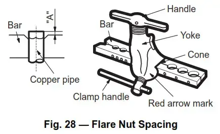
e. Install the correct size flare nut onto the tubing and make the flare connection. Refer to Table 7 for the flare nut spaces.
Table 7 — Flare Nut Spacing
| OUTER DIAM. (MM) | A (MM) | |
| MAX. | MIN. | |
| Ø 1/4” (6.35) | 0.05 (1.3) | 0.03 (0.7) |
| Ø 3/8” (9.52) | 0.06 (1.6) | 0.04 (1.0) |
| Ø 1/2” (12.7) | 0.07 (1.8) | 0.04 (1.0) |
| Ø 5/8” (15.88) | 0.09 (2.2) | 0.08 (2.0) |

f. Apply a small amount of refrigerant oil to the flare connection on the tubing.
g. Align the center of the pipes and/or service valve.

h. Connect both the liquid and gas piping to the indoor unit
i. Tighten the flare nut using a torque wrench as specified in Table 8.
| Brass Flare Size | Recommended Seating Torque for Brass Flare Nuts |
N-m |
| Ø1/4 | 8-10 Ft. – Lbs. | 10.8 to 13.6 |
| Ø3/8 | 15-18 Ft. – Lbs. | 20.3 to 24.4 |
| Ø1/2 | 28-32 Ft. – Lbs. | 38.0 to 43.4 |
| Ø5/8 | 38-42 Ft. – Lbs. | 51.5 to 56.9 |
| Ø3/4 | 50-55 Ft. – Lbs. | 68.0 to 74.6 |

FINAL TUBING CHECK
IMPORTANT: Ensure the certain factory tubing on the indoor unit has not shifted during shipment. Ensure the tubes are not rubbing against each other or any sheet metal. Pay close attention to feeder tubes and ensure the wire ties on the feeder tubes are secure and tight.
DRAIN CONNECTIONS
Connect the drain line. The drain line must not have a trap anywhere in its length, must pitch downwards, and must be insulated up to the outside wall (see Fig. 31). By default, the drain hose is attached to the left-hand side of unit (when facing the back of the unit). However, it can also be attached to the right-hand side.
a. To ensure proper drainage, attach the drain hose on the same side that your refrigerant piping exits the unit.
b. Attach a drain hose extension (purchased separately) to the end of the drain hose.
c. Wrap the connection point firmly with Teflon tape to ensure a good seal and to prevent leaks.
d. For the portion of the drain hose that remains indoors, wrap it with foam pipe insulation to prevent condensation.
e. Remove the air filter and pour a small amount of water into the drain pan to ensure that water flows from the unit smoothly.
Plug the Unused Drain Hole
To prevent unwanted leaks, plug the unused drain hole with the rubber plug provided.
NOTE: For proper orientation of the refrigerant piping, electrical cable and drain lines, refer to Fig. 32.
NOTE: The factory insulation provided with the product is sufficient, therefore adding additional insulation to the refrigerant pipes is NOT recommended. Additional insulation may keep the product from attaching flush to the wall.
NOTE: For applications where gravity cannot be used for drainage, a condensate pump accessory is available.
Consult the condensate pump Installation Instructions for more information.
WIRELESS REMOTE CONTROL INSTALLATION

- Use the two screws supplied with the wireless remote control to attach the mounting bracket to the wall in a location selected by the customer and within operating range.
- Install the batteries in the remote control.
- Place the remote control into the remote control mounting bracket.
NOTE: For remote control operation, refer to the remote control’s owner’s manual.
WIRED REMOTE CONTROL INSTALLATION
The wired remote controller comes with the following items:
- A set of installation instructions and owner’s manuals
- 3 M4X20 Screws to mount on the wall
- 4 wall plugs to mount on the wall
- 2 M4X25 to mount on the switch box
- 2 plastic screw bars to fix on the switch box
- 1 set of batteries
- 1 set of connecting wires to connect to the indoor unit’s main board
 To connect the wired remote controller to the indoor units, connect to the 4-pin connector located on the display board.
To connect the wired remote controller to the indoor units:
- Replace the display board with the shipped kit.
- Install the adapter board (shipped with the kit).
- Connect the adapter board to the new display board. Follow the instructions on the wired controller installation instructions manual for more details.
- Connect the female Molex plug on the adapter board to the male Molex plug from the extension cable shipped with the kit.
- Connect the extension cable to the wired controller
For setup instructions, refer to the controller installation manual.
START-UP
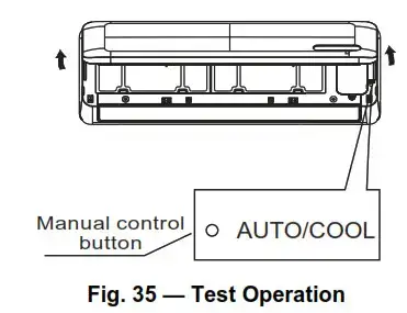
Test Operation
Perform a test operation after completing a gas leak and electrical safety check (see Fig. 35).
- Push ON/OFF on the remote control to begin testing.
NOTE: A protection feature prevents the air conditioner from activating for approximately 3 to 4 minutes. - Push MODE, select COOLING, HEATING, FAN mode to check that all functions work correctly.
- To run the test using the MANUAL button on the indoor unit:
a. Open the front panel of the indoor unit;
b. Push MANUAL once to energize the unit. The set conditions for manual operation are as follows:
•Preset set point: 76°F (24°C)
•Fan speed: AUTO
•Discharge air direction: Pre-set position based on operation in the COOL or HEAT mode. - Set the MANUAL button to OFF (by pushing it twice again) after completing the test operation.
SYSTEM CHECKS
- Conceal the tubing where possible.
- Ensure the drain tube slopes downward along its entire length.
- Ensure all tubing and connections are properly insulated.
- Fasten tubes to the outside wall, when possible.
- Seal the hole through which the cables and tubing pass.
INDOOR UNIT
- Do all remote control buttons function properly?
- Do the display panel lights work properly?
- Does the air deflection louver function properly?
- Does the drain work?
Explain Following Items To Customer (with the aid of the Owner’s Manual):
- How to turn the air conditioner on and off; selecting COOLING, HEATING and other operating modes; setting a desired
temperature; set the timer to automatically start and stop the air conditioner operation; and all other features of the remote control and display panel. - How to remove and clean the air filter.
- How to set the air deflection louver.
- Explain care and maintenance.
- Present the owner’s manual and installation instructions to the customer.
TROUBLESHOOTING
For ease of service, the systems are equipped with diagnostic code display LEDs on both the indoor and outdoor units. The indoor diagnostic display is a combination of flashing LEDs on the display panel or the front of the unit.
Some indoor units display error codes specifying failure modes in the outdoor units. If possible, always check the diagnostic codes displayed on the indoor unit first.
The diagnostic codes displayed in the indoor and outdoor units are listed in Table 9.
INDOOR UNIT DIAGNOSTIC GUIDES
Table 9 — Indoor Unit Diagnostic Codes
| OPERATION LAMP (TIMES) | TIMER LAMP | DISPLAY | ERROR INFORMATION |
| *1 | OFF | EH 00/EH OA | Indoor unit EEPROM parameter error |
| *2 | OFF | EL 01 | Indoor/outdoor unit communication error |
| *3 | OFF | EH 02 | Zero-crossing signal detection error |
| *4 | OFF | EH 03 | Indoor fan operating outside of the normal range |
| *5 | OFF | EC 51 | Outdoor unit EEPROM parameter error |
| *5 | OFF | EC 52 | T3 is in an open circuit or has short-circuited |
| *5 | OFF | EC 53 | T4 is in an open circuit or has short-circuited |
| *5 | OFF | EC 54 | TP is in an open circuit or has short-circuited |
| *5 | OFF | EC 56 | T2B is in an open circuit or has short-circuited |
| *6 | OFF | EH 60 | T1 is in an open circuit or has short-circuited |
| *6 | OFF | EH 61 | T2 is in an open circuit or has short-circuited |
| *12 | OFF | EC 07 | Outdoor fan operating outside of the normal range |
| *9 | OFF | EH Ob | Indoor PCB/Display board communication error |
| *8 | OFF | EL OC | Refrigerant leakage detection |
| *7 | FLASH | PC 00 | IPM malfunction or IGBT OSCP |
| *2 | FLASH | PC 01 | Overvoltage or over low voltage protection |
| *3 | FLASH | PC 02 | Compressor or IPM high temp/pressure protection |
| *5 | FLASH | PC 04 | Inverter compressor drive error |
| *1 | FLASH | PC 08 | Current overload protection |
| *6 | FLASH | PC 40 | Communication error between the outdoor chip and compressor chip |
| *7 | FLASH | PC 03 | Low-pressure protection |
| *1 | ON | — | Indoor unit mode conflict |
| *9 | OFF | EH b1 | Indoor board and Multi-function communication error |
| *11 | OFF | FH Od | Ionizer malfunction |
O (on − light) X (off − light) ☆(flash)
For additional diagnostic information, refer to the service manual.
INDOOR UNIT FUNCTIONAL CODES
Table 10 — Indoor Unit Functional Codes
| DISPLAY | DESCRIPTION |
| dF | Defrost |
| SC | Self-clean |
| CL | Filter cleaning reminder |
| CL | Active Clean (*model dependent) |
| nF | Filter replacement reminder |
| FP | Heating in room temperature under 8°C |
| FC | Forced cooling |
| AP | AP mode of WIFI connection |
| CP | Remote switched off |
| LL | Remote or Wire controller Lock |
| On | Time On |
| Off | Time Off |
| E-C-O | ECO mode |
| SD | Power abnormal detection |
| dl | Receive DR1 signal |
| d2 | Receive DR2 signal |
| d3 | Receive DR3 signal |
| dE | DR input error signal |
| FH OP | AP mode is activated / no WIFI kit installed |
| FH Od | See outdoor unit for Error Code information |
| EH/EC/EL/PC | See outdoor unit for Error Code information |
DUCTLESS START-UP CHECKLIST – Single Zone
Installation Data
Site Address:__________________
City:_______________________State:___________ Zip Code:__________
Installing Contractor:______________ Contractor Contact #: ( ) _____-____
Job Name:___________________ Start-up Date:___________________
Distributor:______________________
System Details
| UNITS | MODEL NO. | SERIAL NO. | CONTROLLER |
| OUTDOOR UNIT | |||
| INDOOR UNIT A | |||
Are the outdoor unit and indoor unit compatible?
YES:______ NO:______
Wiring Electrical
Wire Size and Type Used? AWG:__________ TYPE:_________
Are there any breaks, splices, wire nuts or butt connectors between the outdoor unit and the indoor unit? Was the wiring from the outdoor unit port to the correct indoor unit verified?
REMARKS:______________________
YES:______ NO:______
YES:______ NO:______
Voltage Check
Wiring: Single Zone
| Outdoor Unit Disconnect |
1 (L1 ):GND | Outdoor Unit Terminal Block |
1 (L1):GND | NOTES: | ||
| 2(L2): GND | 2(L2): GND | |||||
| 1 (L1): L2(2) | 1 (L1):2(L2) | |||||
| Indoor Unit Voltage Check @ Outdoor Unit |
1 (L1 ): GND | Indoor Unit Voltage Check @ Indoor Unit |
1 (L1): GND | NOTES: | ||
| 2(L2): GND | 2(L2): GND | |||||
| 1 (L1 ):2(L2) | 1 (L1 ):2(L2) | |||||
| 2(L2):3(S) | 2(L2):3(S) | |||||
| Outdoor Unit Disconnect |
1 (L1): GND | Outdoor Unit Terminal Block |
1 (L1 ): GND | NOTES: | ||
| 2(L2): GND | 2(L2): GND | |||||
| 1 (L1 ): L2(2) | 1 (L1 ):2(L2) | |||||
| Indoor Unit Voltage Check @ Outdoor Unit |
1 (L1 ): GND | Indoor Unit Voltage Check @ Indoor Unit |
1 (L1 ): GND | NOTES: | ||
| 2(L2): GND | 2(L2): GND | |||||
| 1 (L1 ):2(L2) | 1 (L1 ):2(L2) | |||||
| 2(L2):3(S) | 2(L2):3(S) | |||||
Ductless Start-Up Checklist (CONT)
Piping
Leak Check:
The system held 500 psig (max. 550psi) for a minimum of 30 minutes using dry nitrogen. YES:______ NO:______
Evacuation Method:
- Was the Triple Evacuation Method used as outlined in the installation manual? YES:______ NO:______
- Was the Deep Vacuum Method used as outlined in the installation manual? YES:______ NO:_______
- Did the System Hold 500 microns for 1 hour? YES:______ NO:_______
- Does the line set to match the diameter of the evaporator connections? YES:______ NO:_______
- For Conventional Fan Coils, does the line set to match the outdoor unit size? YES:______ NO:_______
Single Zone Piping:
Has the liquid pipe length been measured and the additional charge calculated?
Size:___________ Length:_________ Charge:____________
NOTES:………………….
| PORT | LIQUID SIZE | SUCTION SIZE | LENGTH | CHARGE | NOTES: | ||
| A | |||||||
Performance Check
For 1:1 Single Zone Systems: Adjust the set-point to create an operational call for the desired testing operation. Allow the system to run for a minimum of 10 min. and record the following details:
(Operational data recorded on applicable heads with the wireless remote controller’s Point Check function)
| UNIT | SET-POINT | MODE | T1 | T2 | T3 | T4 | Tb | Tp | Th | LA/Lr |
| A |
NOTE:
- T1 – Ambient Space Temperature Sensor
- T2 – IDU Coil Temperature Sensor
- T3 – Outdoor Coil Temperature Sensor
- T4 – Outdoor Ambient Temperature
- Tb – Suction Line Temperature @PMV
- Tp – Discharge Temperature Sensor
- Th – IPM Board Temperature
- LA/Lr – PMV Temperature
Error Codes
Were there any error codes present at the start-up?
YES:______ NO:______
| Indoor Unit Error Code: | Notes: | |
| Outdoor Unit Error Code: | ||
| Wall Controller: | ||
| 24V Interface: |
Comments:
Copyright 2020 Carrier Corp D 3300 Riverwood Parkway Atlanta GA, 30339 Edition Date: 12/20 Catalog No. 40MAHB-01SI
The manufacturer reserves the right to discontinue or change at any time, specifications or designs without notice and without incurring obligations.
Replaces: NEW