View Fullscreen
H TO T H TO T
H TO T
H TO T
Smoke alarm
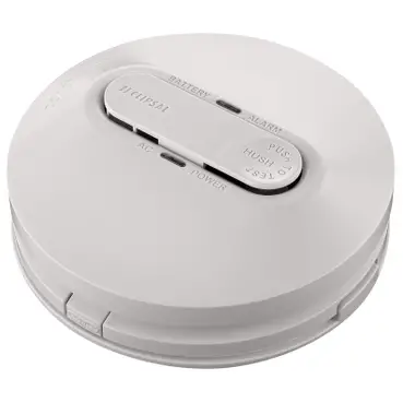
755RLPSMA4
240 V a.c. Mains Power Photoelectric Smoke Alarm with Rechargeable Battery Backup
More information is available
https://download.schneiderelectric.com/files?p_Doc_ Ref=EAV8159103
Scan the QR code for more information about your Clipsal smoke alarm: · What smoke alarms can and cannot do · Developing and practising a plan of escape · What to do if an alarm sounds.
Operating elements
Red LED (battery/alarm indicator)
Test/Hush button
Latch
BATTERY AC
ALARM PUS
HUSH
POWER
EST
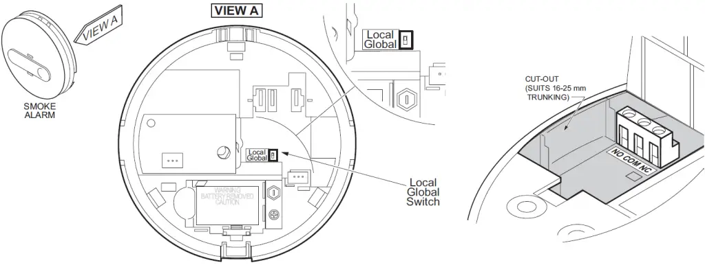
Local/Global switch (for use with separately available relay base 755RB)
Local Global
PUSH TO OPEN
PUSH TO OPEN
Green LED (mains power ON indicator)
[ ]
Battery disconnect switch
LoGcloabl al
Battery disconnect switch
OFF
ON
Installation location
Install more than 1 m away
from air conditioner/heater
>1 m: vents and fans, electrical
sources, appliances
and fittings.
M
Ceiling line
Do not install in garages, kitchens, bathrooms or any area with high levels of moisture, dirt or insects. For garages: A heat alarm is more suitable as it is not affected by particulates.
Dead air space (do not install in these locations) Suitable alarm location
Exposed joists
max. 1500 mm
500 mmmin.
300 mm min.
Flat ceiling
Side wall
500 mm max.
300 mm min.
Example: Class 1a building
Smoke alarm
Recommended additional alarms (or as required by legislation)
Lounge
Bed
Bed
Hallway
Kitchen
Ldy Bath
Bed
Dining / Family
Example: Class 1b building
Smoke alarm
Smoke alarm with evacuation lighting
Dining Kitchen Ldy Bath
Bed
Lounge
Hallway
Bed
Bed
Bed Bed
Storeys with bedrooms:
Alarm in hallway connecting bedrooms
Recommended
additional alarms (or as
Bed
Bed
required by legislation)
Storeys with no bedrooms:
Alarms located in the area of the stairway.
Living
Dining
Basement
Installation
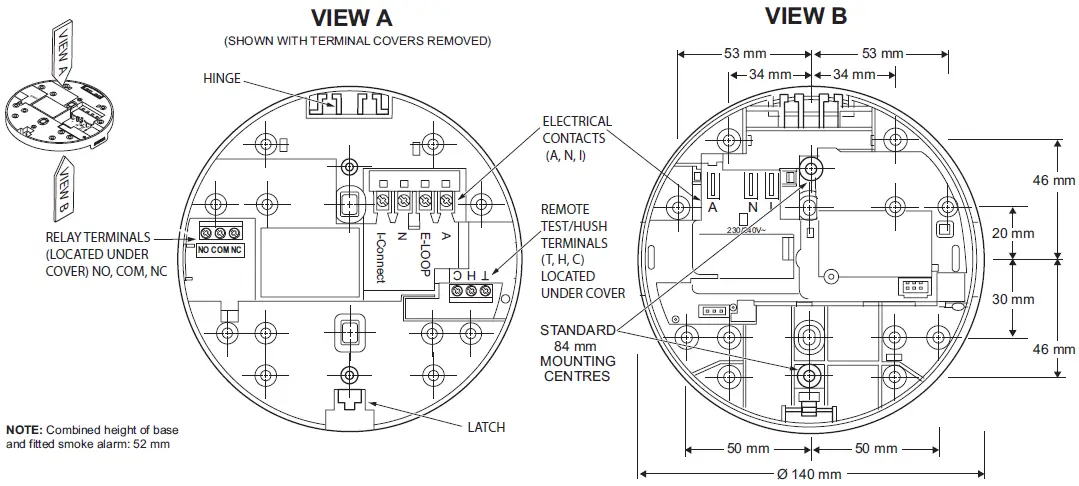
Standard 84 mm Mounting centres (Suits wall switch
mounting brackets, e.g. C-Clips)
53 mm 34 mm
53 mm 34 mm
Cut-out (Suits 16-25 mm Trunking)
Note: Ensure that the alarm base is mounted flat against the mounting surface.
46 mm 20 mm
30 mm 46 mm
PUSH TO OPEN
Ø 140 mm
47 mm (WITH
40 mm
SUPPLIED BASE)
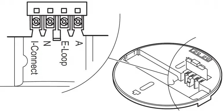
A E-Loop N I-Connect
A E-Loop N I-Connect
Single alarm
Terminal markings:
A: E-Loop: N: I-Connect:
Active/Line (Red) Earth Wire Neutral (Black) Interconnect
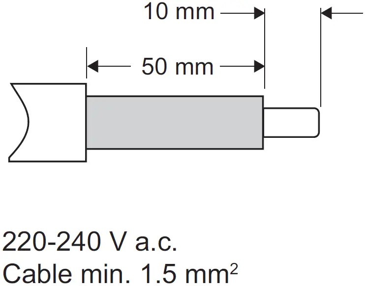
10 mm 50 mm
220-240 V a.c. Cable min. 1 mm2
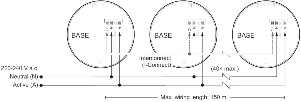
Interconnected alarms
BASE
220-240 V a.c. Neutral (N) Active (A)
A E-Loop N I-C
A E-Loop N I-C
A E-Loop N I-C
220-240 V a.c. Neutral (N) Active (A)
BASE
BASE
Interconnect (I-Connect)
BASE (40× max.)
Max. wiring length: 150 m
Operating the smoke alarm
Alarm sounding
PUS HUSH
Press and hold 3 s…
EST
PUS HUSH
EST
Press and
hold 3 s…
10 min
PUS HUSH
Low battery (1 beep), alarm fault (2 beeps) or alarm memory (LED only)
EST
Press and hold 3 s…
10 hrs
General information
· Leave these instructions with the occupant, to be retained for the life of the alarm.
· This smoke alarm must be installed by a licenced electrician.
· Do not remove dust cover until 24 hours after all construction has been completed. Construction dust and chemicals can cause contamination and false alarms.
· Important: Dust cover must be removed before smoke alarm will operate correctly.
For your safety
DANGER
RISK OF ELECTRIC SHOCK, EXPLOSION OR ARC FLASH · This product must only be installed and serviced
by appropriately qualified and/or licenced electrical personnel. · This product must only be used for the purpose described in these instructions and must be installed in accordance with the wiring rules and regulations in that location. · Isolate the electrical supply before doing any work on this product. · Ensure the product has been correctly installed and tested for safe operation before reconnecting the electrical supply. Failure to follow these instructions will result in death or serious injury.
CAUTION
EQUIPMENT INSTALLATION HAZARD · Ensure active and neutral from mains power are wired
to the correct terminals. · Ensure the green LED is ON when mains power is
supplied. · Ensure the red LED is not flashing quickly. · Test each interconnected unit 1 by 1. Press and hold
the Test button until second burst of 3 beeps has finished. If any unit fails to alarm, check all wiring and connections. Failure to follow these instructions may result in injury or equipment damage.
Operating elements
Activating the battery for use or disconnecting for transport/storage
[ ] Ensure that the battery disconnect switch is set to the Battery ON position after installation. The rechargeable batteries are not connected, nor can the unit be closed onto the base, until the switch has been moved to the Battery ON position.
Choosing the installation location
Prior to installing, ensure there are no obstructions in ceiling mounting locations, such as pipes or cables.
NOTICE
EQUIPMENT INSTALLATION COMPLIANCE This smoke alarm must be installed in accordance with the National Construction Code and any local state legislation requirements. Failure to follow these instructions may result in a non-compliant installation.
Installing the smoke alarm
· Only install smoke alarm indoors in a stand-alone or interconnected set up (see Interconnecting smoke alarms).
· Use minimum cable width 1 mm2 for all wiring, including interconnect wiring where used.
· Do not remove the dust cover until you are ready to test the unit. See
Mounting the smoke alarm
Connecting the smoke alarm (see Single alarm)
Interconnecting smoke alarms (see Interconnected alarms)
CAUTION
EQUIPMENT INSTALLATION HAZARD · All interconnected smoke alarms must be supplied from
the same circuit. · A common Neutral must be used for the Interconnect
to operate. · DO NOT connect the Interconnect wire to Active or
Neutral. · Maximum of 40 interconnected smoke alarms. · Only Clipsal smoke alarms are compatible for
interconnection with this alarm. Failure to follow these instructions may result in injury or equipment damage.
Maximum wire length between first and last alarm is 150 m. Wireless interconnection An optional wireless base (Catalogue No. 755RFB2) may be purchased separately if wired interconnection is not possible. A maximum of 40 smoke alarms can be interconnected using wireless bases.
Operating the smoke alarm
Testing the smoke alarm
CAUTION
DO NOT USE OPEN FLAME
Never use an open flame of any type to test your alarm. Failure to follow this instruction may result in injury or equipment damage.
· Test the smoke alarm once per month to ensure proper operation.
· If no alarm sounds, check that the battery
disconnect switch is in the ON position.
(See
[ ])
If the battery disconnect switch is in the
ON position and the alarm still doesn’t
sound, replace the smoke alarm.
· If the smoke alarm is installed in a mobile home, test weekly and before every journey.
· IMPORTANT: If premises are unoccupied for a more than a few days, a battery test must be undertaken upon return. If the low battery warning sounds, connect mains power (220-240 V a.c.) to the premises or mobile home and allow the built-in battery to recharge.
· Check that all interconnected smoke alarms operate during the test.
Interconnected smoke alarms
· Test each alarm in an interconnected group.
· For each alarm test, ensure that all interconnected alarms operate.
Silencing the smoke alarm (Hush feature)
· When the Test/Hush button is pressed during an alarm event, the smoke alarm is not sensitive to smoke for 10 minutes, after which the alarm resumes normal operation.
· During this hush time, the red LED flashes once every 8 seconds.
· Wait 10 minutes before performing any additional testing to avoid any abnormal alarm responses.
Snoozing low battery, fault and alarm memory indications
Low battery
When the backup battery gets low, the red LED flashes once every 40 seconds, together with a beep sound. You can snooze the low battery indication for 10 hours by pressing the Test/ Hush button for 3 seconds.
Alarm fault
When an alarm fault is detected, the red LED flashes once every 40 seconds, together with 2 beeps. You can snooze the alarm fault indication for 10 hours by pressing the Test/Hush button for 3 seconds.
Alarm memory
In an interconnected alarm group, the red LED on the triggered alarm flashes once every 2 seconds for 72 hours after the alarm beeping has stopped, so that you can identify the unit as the alarm that was triggered. Press the Test/Hush button for 3 seconds to snooze the flashing LED for 10 hours. The snooze function for the alarm memory can be repeated as often as desired up to the 72 hour limit.
LED and sound indications
ALARM MODE
ALARM MEMORY (triggered alarm only)
Operating mode Normal mode / Standby mode Local alarm Interconnected alarm Test mode
Hush mode
Normal
Hushed during alarm
Red LED Sound
1 flash every 40 s
OFF
1 flash Continuous
every 1 s
siren
OFF
Continuous siren
1 flash every 1 s
Siren (3 s)
1 flash every 8 s
OFF
1 flash every 2 s after alarm
stops
1 flash every 2 s after Hush started
OFF OFF
Duration
— — —
10 min Total 72 hrs
Total 72 hrs
Snooze
See Snooze Mode
Low battery mode
Fault mode Low battery Fault Alarm memory
1 flash every 40 s
2 flashes every 40 s
1 flash every 24 s
1 flash every 24 s
1 flash every 40 s
1 beep every 40 s
2 beeps every 40 s
Until battery voltage reaches 7.5 V or above
Until fault has been cleared
OFF
10 hrs
OFF
10 hrs
OFF
10 hrs
Green LED
Mains power ON
ON
—
—
SNOOZE MODE
Troubleshooting
ALERTS AND SILENCING
Problem
Cause and Resolution
Alarm sounds and the red LED is blinking rapidly
Smoke has activated the smoke alarm.
Vacate the building immediately and call the Fire and Emergency Services. See False Alarm section.
Alarm sounds but the red LED is OFF
Smoke has activated an interconnected alarm, located somewhere else in the building.
Vacate the building immediately and call the Fire and Emergency Services. See False alarm section.
Smoke alarm is sounding, it stops when Test/Hush is pressed
Hush or silence feature has been activated for 10 minutes providing the smoke density does not increase.
Ensure you are safe and have put out the source of the smoke. See False alarm section.
Red LED is flashing every 2 seconds
Alarm memory has been activated, indicating that this alarm was the triggered alarm in the group.
LED stops flashing after 72 hours. Press Test/Hush to snooze the LED indication for 10 hours.
Smoke alarm is sounding and does not stop when Test/ Hush is pressed
Smoke density is too high for the Hush or Silence feature to activate.
Vacate the building immediately and call the Fire and Emergency Services. See False alarm section.
When Test/Hush button is pressed for three seconds alarm sounds briefly
The smoke alarm horn is indicating that all electronic circuitry, horn and battery are working.
Normal test condition.
Test regularly to ensure proper operation.
When Test/Hush button is pressed for three seconds alarm does not sounds
The smoke alarm may not be operating correctly.
Check and ensure that the green LED is ON and the red LED flashes once every 40 seconds. If the problem persists contact an electrician for replacement.
One audible beep every 40 seconds
Low battery warning.
Test and check the mains power connection.
Ensure the battery disconnect switch is in the ON position.
Two audible beeps every 40 seconds
The smoke alarm may not be operating correctly.
Clean smoke alarm according to the Maintenance, Repairs and Service section. If problem persists, contact an electrician for replacement.
Green LED off
Mains power may be disconnected.
Check mains power ON. Main circuit breaker may have tripped. Wiring could be wrong.
Red LED flashes very quickly (3 times
per second)
Neutral connection is bad or wiring is wrong.
Check wiring and connection of smoke alarms with flashing red LED and rectify wiring issue immediately.
BEEPING
POWER
False Alarm
In the event of a false alarm in an interconnected group, it is important to identify the triggering alarm(s). These alarms may need to be cleaned, serviced or replaced if necessary.
When alarms are sounding without any smoke present:
· Identify which smoke alarm(s) are being triggered Look for the alarm(s) with sound and red LED flashing.
· Unclip all identified smoke alarms. Any remaining interconnected alarms will stop alarming in 1 minute.
· If the alarming stops before you have identified the alarms that are being triggered, look for any alarms with the red LED flashing once every 2 seconds. This flashing can be snoozed for 10 hours by pressing the Test/Hush button for 3 seconds. The snooze function can be repeated as often as desired up to the 72 hour limit.
· Clean affected smoke alarms in accordance with the Maintenance, Repairs and Service section.
· Re-install and test all the smoke alarms.
If all of the above fails, contact a licenced electrician for replacement.
Maintenance, Repairs and Service
Maintenance
It is recommended that the smoke alarm is inspected monthly to ensure it is free from dirt, dust and insects. The alarm can be vacuumed or brushed with a soft brush to remove dust, dirt or kitchen grease that has accumulated. Apply a small amount of insect surface spray to a cloth and wipe around alarm/s every 3-6 months to mitigate insect ingress.
ALWAYS TEST THE SMOKE ALARM AFTER CLEANING
Repairs and Service
NOTICE
EQUIPMENT MAINTENANCE INSTRUCTIONS
· Test this smoke alarm regularly to ensure the unit is functional and that the battery is in good condition.
· Replace the smoke alarm 10 years after date of manufacture.
· Do not open the smoke alarm casing or repair the smoke alarm yourself. There are no user-serviceable parts inside.
Failure to follow these instructions may result in equipment malfunction or failure.
Disposal
As the smoke alarm does not contain any radioactive material, disposal with normal rubbish is permitted in Australia and New Zealand. Before disposal, move the battery disconnect switch to the disconnect position. This will prevent the low battery warning beep when the battery eventually discharges.
Technical data
Main Power Source Secondary Power Source Operating Current Battery Life Sensing Type
Operating Temperature Ambient Humidity Interconnecting
Terminal Provisions
Horn Level Approvals Complies with
220240 V a.c., 50 Hz
Rechargeable lithium battery
40 mA 10 years
Photoelectric. This alarm contains NO radioactive material.
0 °C to 45 °C
5% to 95%
Wired: 40 alarms over 150 metres maximum Wireless: 40 alarms maximum
Active, Neutral, Loop and Interconnect terminals, each accommodates 2 × 1.5 mm2
85 dB at three metres minimum
Activfire SAI Global RCM AS 3786: 2014, AS/NZS 60065 and AS/NZS 60950.1
It is recommended to dispose of this device at an authorised electronic waste collection point. Professional recycling protects people and the environment against potential negative effects.
Trademarks and certifications
Schneider Electric acknowledges that the Australian Standard Certified Product logo is a trademark of SAI Global, and that the Activfire Certified logo is a trademark of CSIRO.
Warranty
We warrant this product to be free from defects in materials and workmanship for a period of 5 (five) years from the date of installation.
Customer care
If you have technical questions, please contact the Customer Care Centre in your country.
Australia Schneider Electric (Australia) Pty Ltd Customer Care Australia: 13 73 28 e: [email protected] www.schneider-electric.com.au
New Zealand Schneider Electric (NZ) Ltd After hours service: 0800 735 4357 (NZ only) Customer Care NZ: 0800 652 999 e: [email protected] www.schneider-electric.com
QGH8213801_01
]]>CLIPSAL FIRETEK 755RB Smoke Alarm Mounting Base with Integrated Relay

Scan the QR code for more information about your Clipsal smoke alarm:
- What smoke alarms can and cannot do
- Developing and practicing a plan of escape
- What to do if an alarm sounds.
Operating Elements
Installation
- Strip the active, neutral and interconnect (if used) wires back to the strip length shown here.
- Connect wires to terminals on the base and ensure the screws are fully tightened.
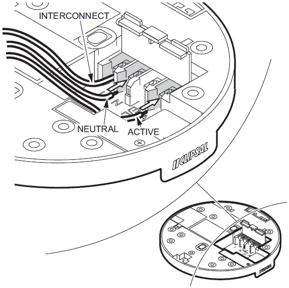
- Clip terminal cover closed to avoid contact with live terminals.
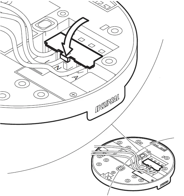
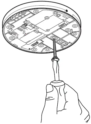
- Screw the base on to the ceiling.
- Clip the smoke alarm into the base at the hinge.
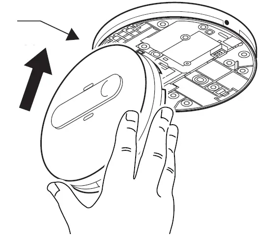
- Use gentle pressure to latch the smoke alarm onto the base (take care to align the pins and terminals).
 Note: When 755PSMA2/4 alarms are used ensure the 9V battery is fitted prior to mounting.
Interconnecting Smoke Alarms
Terminal markings:
A: Active/Line (Red)
E-Loop: Earth Wire
N: Neutral (Black)
I-Connect: Interconnect
Relay Operation and Configuration
Remote Test/Hush Feature
General Information
- Leave these instructions with the occupant, to be retained for the life of the product.
- The smoke alarm base must be installed by a licensed electrician.
Compatibility
This product is compatible with the following Clipsal Smoke alarms:
- 755RLPSMA2
- 755RLPSMA4
- 755PSMA2
- 755PSMA4
For Your Safety
RISK OF ELECTRIC SHOCK, EXPLOSION OR ARC FLASH
- This product must only be installed and serviced by appropriately qualified and/or licensed electrical personnel.
- This product must only be used for the purpose described in these instructions and must be installed in accordance with the wiring rules and regulations in that location.
- Isolate the electrical supply before doing any work on this product.
- Ensure the product has been correctly installed and tested for safe operation before reconnecting the electrical supply.
Failure to follow these instructions will result in death or serious injury.
CAUTION
EQUIPMENT INSTALLATION HAZARD
- All interconnected smoke alarms (max 40) must be supplied from the same interconnection. A common Neutral must be used for the interconnect to operate.
- DO NOT connect the interconnect wire to Active or Neutral.
- Do not connect to a circuit which also has inductive loads connected. Spikes generated by switching inductive loads may damage electrical components within the base or connected smoke alarm.
- Do not open this base, as there are no user-serviceable parts inside.
Failure to follow these instructions may result in injury or equipment damage.
Choosing the Installation Location
EQUIPMENT INSTALLATION COMPLIANCE
This product must be installed in accordance with the National Construction Code and any local state legislation requirements.
Failure to follow these instructions may result in a non-compliant installation.
Installation
- Only install the product indoors in a stand-alone or wired interconnected set up (see Interconnecting smoke alarms).
- Do not attach to surfaces which are damp, freshly painted or otherwise electrically conductive (e.g. metallic surfaces).
Mounting and connecting the smoke alarm
Follow the illustrations:
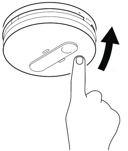
- Turn on the mains power and check:
- The green LED illuminates to show active connection to power.
- The red LED pulses every 40 seconds to show correct operation.
- Press Test/Hush to check smoke alarm functions.
Interconnecting Smoke Alarms
Always test operation after adding or removing smoke alarms to an interconnection setup.
Relay Operation and Configuration
Global/Local Relay Setting
The 755 series smoke alarms have a Global/Local switch for use with 755RB mounting base only.
When the Global/Local switch is set to Local, only activation of the connected alarm will operate the relay.
When the Global/Local switch is set to Global, activation of any smoke alarm that is interconnected with the base causes the relay to operate.
The default setting is Global.
Relay Operation
When the smoke alarm is triggered, the relay on the relay base will operate according to the description in Global/Local Relay Setting both when mains or backup battery power is applied.
Relay Output Connection
For connecting auxiliary devices, the relay mounting base terminal specifications are:
- NO (Normally Open)
- COM (Common)
- NC (Normally Closed).
- Wiring capacity 2 × 1.5 mm2 each
- Combination screw head type.
- Voltage-free and segregated from the mains supply terminal connections with a physical barrier.
- Relay rating is 250 V a.c., 2 A.
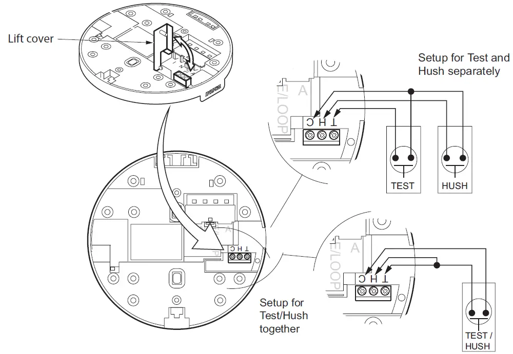
Remote Test/Hush Function
The Remote Test/Hush feature is controlled by the smoke alarm. Bases provide optional connection for remote test/hush buttons (dry contact momentary remote switches e.g. Clipsal bell press switches).
Connection Options for Remote Test/Hush Buttons
- Connect remote buttons as either separate Test and Hush buttons, or as single Test/Hush button.
- Wiring capacity of each terminal is 2×1.5 mm2 cables.
- Terminal screws are combination screw head type.
- Max. cable length to Remote Test/Hush switch is 20 m.
Test Function – When No Smoke Present
Test the LOCAL Smoke Alarm
Press and hold either the Remote Test button or the Local Test/Hush button and release within 4 seconds. Only the local smoke alarm will sound.
Test the LINKED Smoke Alarms
Press and hold either the Remote Test button or the Local Test/Hush button for more than 5 seconds. The linked alarms will sound.
Hush Function – When Smoke Present
To hush a smoke alarm, identify the unit which has triggered by the flashing red LED (Unit will not silence if it does not have a flashing red LED.) Press and hold the local Test/Hush button or the remote hush button for 40 seconds. All smoke alarms that are interconnected will also fall silent.
If multiple interconnected alarms have detected smoke and are flashing red LEDs, then press the Remote Hush button or the local Test/Hush button on each alarm to silence them.
Technical Data
| Mains Power Source | 220-240 V a.c., 50 Hz |
| Operating Temperature | 0 °C to 45 °C |
| Ambient Humidity | 5% to 95% |
| Interconnecting | Max 40 alarms (wired over 150 m) |
| Terminal Provisions | Active, Neutral, Loop and Interconnect terminals, each accommodates 2 × 1.5 mm2 |
| Relay Rating | 250 V a.c., 2 A |
| Relay Contacts | NO/COM/NC voltage free contacts |
| Remote Input | Dry contact momentary switch (for Remote Test/Hush function) |
| Approvals | Activfire RCM |
| Complies with | AS/NZS 60065, AS/NZS 60950.1 |
Trademarks and Certifications
Schneider Electric acknowledges that the Australian Standard Certified Product logo is a trademark of SAI Global, and that the Activfire Certified logo is a trademark of CSIRO.

Warranty
We warrant this product to be free from defects in materials and workmanship for a period of 5 (five) years from the date of installation.
Customer Care
If you have technical questions, please contact the Customer Care Centre in your country.
Australia
Schneider Electric (Australia) Pty Ltd Customer Care Australia: 13 73 28
Email: [email protected]
www.schneider-electric.com.au
New Zealand
Schneider Electric (NZ) Ltd
After Hours Service: 0800 735 4357 (NZ only) Customer Care NZ: 0800 652 999
Email: [email protected]
www.schneider-electric.com
![]()
 by Schoneider Electric
Iconic® Series
USB Charging Module
Installation Instructions![]()
PDL342USB2AC-VW Dual USB Charging Mechanism 40E2USBACM-VW
PDL342USB-VW 40E1USBM-VW USB Charging Mechanism
40E2USBM-VW PDL342USB2-VW Dual USB Charging Mechanism
NOTICE
HAZARD OF EQUIPMENT DAMAGE (LOAD)
The USB Charging Mechanism is intended for devices that are designed to be recharged via a USB port.
- Do not attempt to connect devices that are not designed to be charged via a USB port.
- Do not parallel-connect the USB ports in order to achieve higher current output. The ports are intelligent ports that communicate with devices to optimize the charge current.
- Always use the USB charging cable supplied with the device to be charged.
- There are no user-serviceable parts inside the USB charging mechanism.
Failure to follow these instructions may result in damage to the USB Charging Mechanism and connected equipment.
NVE75248-02
12-2018
For your safety

 DANGER
HAZARD OF ELECTRIC SHOCK, EXPLOSION, OR ARC FLASH
• This product must be installed and serviced by appropriately qualified and/or licensed electrical personnel.
• Isolate the electrical supply before doing any work on this product.
• Ensure that the product has been correctly installed and tested for safe operation before reconnecting the electrical supply.
Failure to follow these instructions will result in death or serious injury.
WARNING
RISK OF ELECTRIC SHOCK
Hazardous voltage and electrical current may be present at the wire leads of this product even when the device is switched off.
• Lockout and tag the input circuit before accessing the wiring connections.
• Use the supplied terminal block to connect the USB Charging Mechanism to the electrical circuit.
• After wiring, wrap the terminal block with insulating tape.
Failure to follow these instructions can result in death or serious injury.
CAUTION
HAZARD OF EQUIPMENT DAMAGE
Install the device according to the instructions in this document.
• Pay attention to the specifications and wiring diagrams related to the installation.
• Do not use this product for any other purpose than specified in this instruction.
Failure to follow these instructions can result in minor injuries or equipment damage.
NOTICE
RISK OF EQUIPMENT DAMAGE OR MALFUNCTION (WIRING CONNECTIONS)
To avoid damaging the equipment and possibly voiding the warranty:
• Test operation during installation and correct any wiring errors immediately.
• Keep cable insulation away from the sides of the enclosure to avoid possible damage or long-term degradation of the cable insulation.
Failure to follow these instructions can result in equipment damage or malfunction.
Unit operation
• Connect device(s) to the USB port(s) on the USB charging module using the USB cable supplied with the device.
• The USB charging module will negotiate with each device to provide an optimized charging current.
• If two high-demand devices such as large tablets are connected to a dual-port USB charging module, the devices will negotiate with the module for the amount of charge current they require. As connected devices increase their charge level, the amount of current they require will decrease.
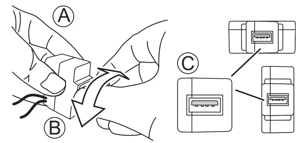
Setting the USB port orientation during installation
1. Hold the body of the USB Mechanism with one hand .
2. Use your other hand to rotate the USB Port Head in either direction until the Head clicks into place. The Head rotates in 90° increments.
3. Keep rotating the USB Port Head until you reach the desired orientation. Once installed, the USB port orientation should be as shown in , or as the customer requires.
Wiring diagram
• Use the terminal bock supplied with the USB charger to connect the module to the mains circuit.
• After wiring, wrap the terminal block with insulation tape.
Technical specifications
| Parameter | 40E2USBACM-VW PDL342USB2AC-VW | 40E1USBM-VW PDL342USB-VW | 40E2USBM-VW PDL342USB2-VW | |
| Nominal operating voltage | 220-240 VAC | |||
| Nominal operating frequency | 50 Hz | |||
| Mounting/installation options | 1, 2 & 3 gang wall plates as well as the extra switch position in single, double, and quad-socket outlets | |||
| Maximum input current | 300 mA | 100 mA | 200 mA | |
| USB port type Maximum port output | 1x Type A
5 VDC, Up to 2.4 A |
1x Type C
5 VDC. Up to 3.1 A |
1x Type A
5 VDC, 1.5 A |
2x Type A
5 VDC, 2.1 A |
| Maximum unit output | 5 VDC, 3.1 A | 5 VDC, 1.5 A | 5 VDC, 3.1 A | |
| Mounting depth in mm | 55 mm | 40 mm | 55 mm | |
| Short circuit protection | Yes | |||
| Thermal over-current protection | Yes | |||
| Over-temperature protection | Yes | |||
| Thermal fuse | Yes | |||
| Multi–gang plate capacity | Maximum 2 modules per plate | Maximum 3 modules per plate | Maximum 2 modules per plate | |
| USB port orientation | Independent of the mechanism body orientation | |||
| Available cap styles | Color packs for USB port caps: Vivid White (VW), Warm White (WY), Cool Grey (CY), Anthracite (AN). Ash Grey (AG) | |||
| Compliances standards | AS/NZS 61558.2.16 | |||
| EMC compliance | AS/NZS CISPR 22, AS/NZS CISPR 24, AS/NZS 61000-3-2 AS/NZS 61000-3-3 | |||
| MEPS standard | 4665 | |||
Troubleshooting
| Problem | Recommended Resolution |
| A connected device is not charging. | • If the charging port is on a Dual Port USB Charging Mechanism, connect the device to the other charging port. If the device charges, there may be a problem with the mechanism charging port. • Connect the device to the charging port using another compatible USB cable. If the device charges, replace the faulty cable. • Connect the device to another compatible charger. If the device charges, there may be a problem with the mechanism charging port. |
| A large tablet (or similar high-demand device) takes an unusually long time to charge. | • If the device is connected to a Single Port USB Charging Mechanism, the maximum output from the port (1.5 A) may be less than the optimal output required by the device. The device should still charge, albeit over a long period of time. • The Ionic Dual Port USB Charging Mechanism has a higher maximum output and is better suited to charge higher-demand devices such as large tablets. • If the cable being used to connect the device to the charger is not the cable that was supplied with the device, try a genuine cable. Cheap non-reputable cables are a common source of charging issues with devices. |
| Two large tablets (or similar high-demand device) take longer to charge when both are connected to the Dual Port USB Charging Mechanism. | • On dual port chargers, the double type A charger has a single output rate of 2.1 A, except when both ports are used together it reduces to a maximum output rate of 3.0 A. Chargers with Type A (2.4 A output) and Type C (3.0 A output) have a reduced output of 3.0 A when used together. • When two high-demand devices that are low on charge are connected to the Dual Port Mechanism, the maximum output is shared between the two charging ports and each device may therefore receive less than optimum charging output. |
Customer care
Warranty Information (Australia)
We warrant this product for 2 years.
visit https://www.schneider-electric.com.au/en/about-us/legal/terms-and-conditions.jsp for details.
Our goods also come with guarantees that cannot be excluded under the Australian Consumer Law. You are entitled to a replacement or refund for a major failure and compensation for any other reasonably foreseeable loss or damage. You are also entitled to have the goods repaired or replaced if the goods fail to be of acceptable quality and the failure does not amount to a major failure.
Warranty information (New Zealand)
We warrant this product for 2 years.
visit https://www.schneider-electric.co.nz/en/about-us/legal/terms-and-conditions.jsp
for details. Schneider Electric (Australia) Pty Ltd
33-37 Port Wakefield Road,
Gepps Cross, SA 5094
Customer Care: 13 73 28
Email: [email protected]
www.schneider-electric.com.au
Schneider Electric (NZ) Ltd
38 Businesss Parade South, HighBrook
East Tamaki, Manukau 2013
Customer Care: 0800 652 999
Email: [email protected]
www.schneider-electric.co.nz
Schneider Electric reserves the right to change specifications, modify designs and discontinue items without incurring obligation, and whilst every effort is made to ensure that descriptions, specifications, and other information in this catalog are correct, no warranty is given in respect thereof and the Company shall not be liable for any error therein.
© Schneider Electric 2018
This material is copyright under Australian, New Zealand, and international laws. Except as permitted under the relevant law, no part of this work may be reproduced by any process without prior written permission of and acknowledgment to Schneider Electric.
Patent notice
This product is the subject of one or more patent and/or design applications and/or registrations. More information can be found on our website