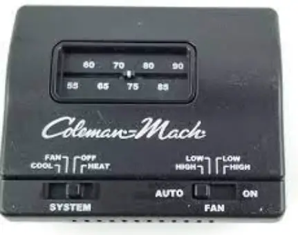
Coleman 7330F3852 Thermostat
Specifications
- DIMENSIONS
6 x 5 x 2 inches - WEIGHT
- 6 ounces
- COLOR
- Black
- VOLTAGE
12 Volts - MOUNTING TYPE
Wall Mount - BRAND
Coleman
Introduction
These thermostats are designed to operate all R.V. Products ceiling assemblies, which control the air conditioner 115 VAC circuits through 12 VDC relays. Wiring is required between the thermostat and the ceiling assembly. The thermostat wiring is field installed and must be considered before wall paneling and ceiling panels are in place. Wall thermostat-controlled air conditioners are normally OEM (Original Equipment Manufacturer) installed. Wall thermostat-controlled air conditioners may be installed for aftermarket applications with additional considerations given to the thermostat wire routing. The 7330*335* and 7330*385* thermostat may also operate any RV furnace 12 VDC control circuit not exceeding one amp. All thermostats are equipped with a replaceable 2 amp fuse located on the front of the thermostat body.
INSTALLATION INSTRUCTIONS
BE SURE ALL ELECTRICAL POWER HAS BEEN DISCONNECTED FROM THE AIR CONDITIONER, THE CEILING ASSEMBLY, AND THE POWER SUPPLY.
These instructions are provided for the proper mounting of the thermostat itself. An Operation Chart and Terminal Cross Reference Chart are provided to show thermostat capabilities. The wiring procedure is dependent upon the ceiling assembly to be matched with this component and is provided in the ceiling assembly installation instructions.
Recreation Vehicle Products suggests the thermostat wiring be a minimum of 18 gauges.
THERMOSTAT LOCATION
This thermostat is a sensitive instrument. For accurate temperature control and comfort, the following considerations should be taken into account:
- Locate the thermostat on an inside wall about five feet above the floor. Pick a dry area where air circulation is good. The thermostat should be mounted within a reasonable distance from the appliance the thermostat will control. This will assure a more accurate temperature relationship between the thermostat and the appliance the thermostat will control.
- Do not install the thermostat where there are unusual heating conditions; such as direct sunlight, heat producing appliances (television, radio, wall lamp, etc.) or a furnace or air conditioner supply register.
ROUTING THE THERMOSTAT WIRE BUNDLE
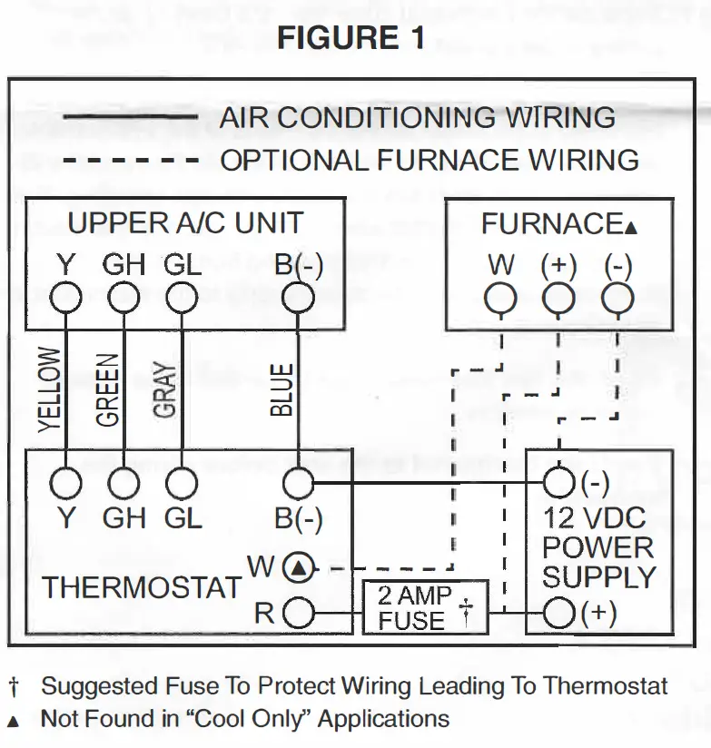
A separate wire bundle to power the 12 VDC thermostats will need to be routed between the thermostat and the power supply. Both positive and negative must be brought up to the thermostat.
If a 12 VDC furnace is also to be operated, additional wiring will need to be routed and a definite furnace location defined. See Figure 1.
- Route the wire bundle between the thermostat and the ceiling assembly. Allow an additional 6 inches of length at both the thermostat and the ceiling assembly. This will give the installer the required slack necessary for wiring. See Figure 1.
- Route the separate 2-wire thermostat bundle between the thermostat and the power supply. Allow 6 inches of additional wiring on both ends. See Figure 1:
- If a 12 VDC furnace is to be operated, route a wire bundle between the thermostat and the furnace. Allow an additional 6 inches at both ends. See Figure 1
- If stapling the wire bundle during the routing process, be careful not to pierce the thermostat wiring insulation.
ATTACHING THE WALL THERMOSTAT
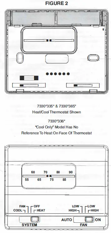
- Separate the thermostat cover from the base by gently pulling at the top and bottom. See Figure 2.
- If this thermostat is a replacement thermostat for one which has failed or no longer meets the needs of the system: note the thermostat wiring on the back of the old thermostat subbase, and the system function each wire was operating. This will save time and trouble when rewiring the new thermostat. Before removing the thermostat wiring from the old thermostat, make sure the power supply to the thermostat is disconnected.
- Attach the new thermostat base to the wall at the desired mounting location.
Mount the thermostat to the wall before wiring the thermostat
WIRING THE WALL THERMOSTAT
TO PREVENT POSSIBLE DAMAGE TO THE EQUIPMENT OR PERSONAL INJURY DUE TO ELECTRICAL SHOCK, BE SURE THAT ALL ELECTRICAL POWER TO THE THERMOSTAT HAS BEEN DISCONNECTED BEFORE THE WIRING PROCEDURE.
- Strip the 12-volt supply wire ends approximately 3/8 of an inch.
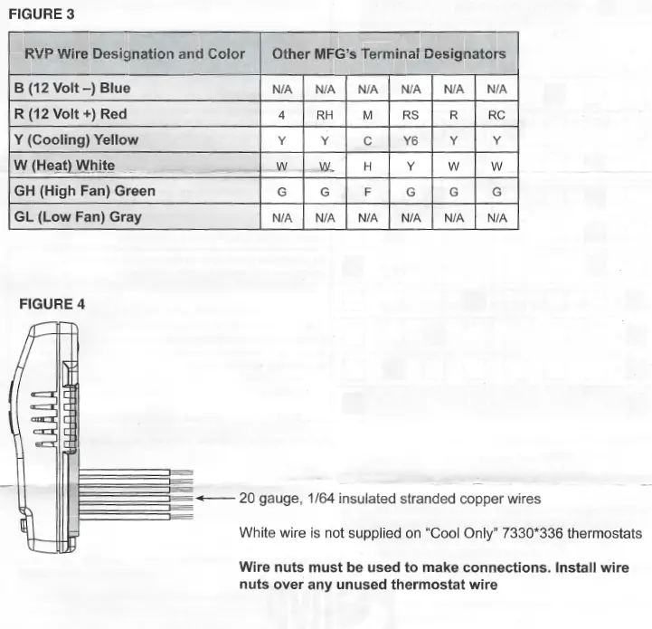
- Use the Wire Cross Reference Chart (See Figure 3) and connect the appropriate conductor to the wire which protrudes from the back of the thermostat (See Figure 4). If this is a first-time installation, note the thermostat wire color for future reference in order to properly connect the thermostat wiring to the ceiling assembly.
- Attach the negative and positive 12-volt power supply wires to the appropriate wire on the thermostat. It is important to identify the positive and negative power supply wires before connecting to insure proper thermostat operation.
If this is a replacement thermostat and there is no negative 12 VDC supply at the thermostat, a negative wire from the power supply to the thermostat must be added.
- If a furnace system is to be operated from the thermostat, strip and attach the furnace system wires.
- Gently push the excess thermostat wiring back into the wall opening. Because the wall may have a different temperature inside when compared to the outside, fill the wall opening with non-combustible insulation. Ensure that wires cannot contact screws or sharp edges in the wall cavity.
- Snap the thermostat body onto the base.
- Turn the thermostat system switch to the “OFF” position.
- After the entire system (including the ceiling assembly and rooftop air conditioner) has been properly installed, restore the electrical power to the thermostat.
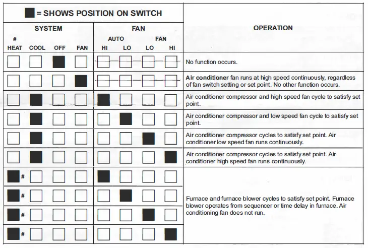
OPERATION
The chart below shows the system functions with the 7330*335* and 7330*385* thermostats. After the entire air conditioning system (and furnace system) is installed, check each position function. Disregard references to heat functions when using the 7330*336* “Cool Only” thermostat All cooling functions controlling to set point have a short cycle protection time delay of 3 minutes. There will be no delay if the cycle OFF time exceeds 3 minutes.
# There is no heat switch or furnace function available with the 7330*336* “Cool Only” thermostat.
FREQUENTLY ASKED QUESTIONS
Can I use this to replace digital Dometic thermostat?
No, it can’t be used to replace digital Dometic thermostat.
Is this the same or will it replace Coleman Mach RVP no. 7330F3858?
Yes, 6 wire 2 stage.
Why is it only blowing air out the AC and not the furnace too?
To blow out through the heater part, you are supposed to have it on heat.
Does this thermostat require soldered connections?
No, this thermostat doesn’t require soldered connections.
What holds the batteries on place?
It doesn’t have a battery compartment as it isn’t powered by batteries. It is powered from the wiring that connects to it.
Is it time delayed?
No, it isn’t time delayed.
Will this work with the Coleman 48203c966 Mach 3+ AC unit?
Yes, it will work with the Coleman 48203c996 Mach 3+ AC unit.
Does Coleman Mach thermostat have batteries?
No, it isn’t operated by batteries.
Can I replace my RV thermostat with any thermostat?
Some RV thermostats can only be used with RVs that have heating systems; they cannot be used with RVs that have both heating and cooling systems. Other thermostats can control both heating and cooling. Make sure the thermostats you consider will work with the equipment in your RV.
Is My RV thermostat bad?
If the thermostat in your RV has a blank screen or is not reacting when you change the temperature, it can be broken. You can restart the system by changing the batteries in your thermostat, performing checks with a multimeter, or responding to error codes. If not, your thermostat might need to be replaced.
How does a thermostat work in an RV camper?
The RV thermostat functions as a conduit between you and your furnace and HVAC system. It instructs those systems on when to operate, and in the case of programmable RV thermostats, it can even adjust temperatures in accordance with your predetermined preferences.
Is there a difference between an RV thermostat and a home thermostat?
RV thermostats require 12V DC power, thus 24V AC-only home thermostats cannot be used in place of them. Digital home thermostats, on the other hand, feature inbuilt batteries that allow them to control RV heaters and air conditioners, resulting in a flexible, temperature-accurate climate management system inside the car.
Can thermostats go bad?
The normal lifespan of a thermostat for upkeep, repair, or replacement is variable (unlike air conditioners that need a tune-up every year). However, in general, you can count on your thermostat to endure for at least ten years. Thermostats may start acting up after ten years.
Who makes Coleman Mach?
Airxcel makes Coleman Mach.
Can you put a smart thermostat in an RV?
With WiFi and Bluetooth cabin comfort management, it is THE smart thermostat available in the aftermarket for recreational vehicles.