CyberPower User Manual
PRODUCT REGISTRATION
Thank you for purchasing a CyberPower product. Please take a few minutes to register your product at www.cpsww.com/registration. Registration certifies your product’s warranty, confirms your ownership in the event of a product loss or theft and entitles you to free technical support.
IMPORTANT SAFETY WARNINGS
(SAVE THESE INSTRUCTIONS)
This manual contains important safety instructions. Please read and follow all instructions carefully during installation and operation of the unit. Read this manual thoroughly before attempting to unpack, install, or operate your UPS.
- CAUTION! To prevent the risk of fire or electric shock, install in a temperature and humidity controlled indoor area free of conductive contaminants. (Please see specifications for acceptable temperature and humidity range).
- CAUTION! To reduce the risk of electric shock, do not remove the cover. There are no user serviceable parts inside.
- CAUTION! Hazardous live parts inside can be energized by the battery even when the AC input power is disconnected.
- CAUTION! The UPS must be connected to an AC power outlet with fuse or circuit breaker protection. Do not plug into an outlet that is not grounded. If you need to de-energize this equipment, turn off and unplug the unit.
- CAUTION! To avoid electric shock, turn off the unit and unplug it from the AC power source before installing a computer component.
- CAUTION! Not for use in a computer room as defined in the Standard for the Protection of Electronic Computer/Data Processing Equipment, ANSI/NFPA 75.
- CAUTION! To reduce the risk of fire, connect only to a circuit provided with 20 amperes maximum branch circuit over current protection in accordance with the National Electric Code, ANSI/NFPA 70.
- CAUTION! Risk of explosion if battery is replaced by an incorrect type. Batteries shall be installed by service personnel, and the replacement of batteries with a suitable recommended type. Dispose of used batteries according to the instructions.
- CAUTION! Do not dispose of batteries in a fire. The batteries may explode.
- CAUTION! Do not open or mutilate batteries. Released electrolyte is harmful to the skin and eyes. It may be toxic.
- DO NOT USE FOR MEDICAL OR LIFE SUPPORT EQUIPMENT! CyberPower Systems does not sell products for life support or medical applications. DO NOT use in any circumstance that would affect operation and safety of life support equipment, any medical applications or patient care.
- DO NOT USE WITH OR NEAR AQUARIUMS! To reduce the risk of fire or electric shock, do not use with or near an aquarium. Condensation from the aquarium can cause the unit to short out.
INSTALLING YOUR UPS SYSTEM
UNPACKING
Inspect the UPS upon receipt. The box should contain the following:
- UPS unit
- User’s manual
- USB device cable
*PowerPanel® Personal Edition software is available on our website. Please visit www.cpsww.com and go to the Software Section for free download.
HOW TO DETERMINE THE POWER REQUIREMENTS OF YOUR EQUIPMENT
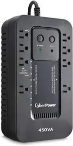
- Ensure that the equipment plugged into the UPS does not exceed the UPS unit’s rated capacity (450VA/260W for EC450G, 550VA/330W for EC550G, 750VA/450W for EC750G, 650VA/390W for EC650LCD, and 850VA/510W for EC850LCD). If the rated capacities of the unit are exceeded, an overload condition may occur and cause the UPS unit to shut down or the circuit breaker to trip.
- There are many factors that can affect the amount of power that your electronic equipment will require. For optimal system performance keep the load below 80% of the unit’s rated capacity.
HARDWARE INSTALLATION GUIDE
- Your new UPS may be used immediately upon receipt. However, after receiving a new UPS, to ensure the battery’s maximum charge capacity, it is recommended that you charge the battery for at least 8 hours. Your UPS is equipped with an auto-charge feature. When the UPS is plugged into an AC outlet, the battery will automatically charge when it’s turned on or turned off.
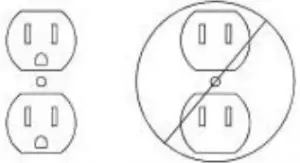
- With the UPS unit turned off and unplugged, connect your computer, monitor, and any other peripherals requiring battery backup from the SURGE/BATTERY outlets. Plug the other peripheral equipment (e.g. printer, scanner, speakers, etc.) into the full-time surge protection outlets. DO NOT plug a laser printer, paper shredder, copier, space heater, vacuum cleaner, sump pump, or other large electrical device into the “Battery and Surge Protected Outlets”. The power demands of these devices will overload and possibly damage the unit.
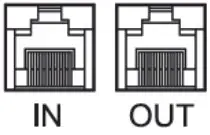
- To protect a fax, phone, or modem line, connect a telephone cable from the wall jack outlet to the IN jack of the UPS. Connect a telephone cable from the UPS OUT jack to protect a modem port on the computer, a telephone, or fax machine.
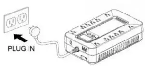
- Plug the UPS into a 2 pole, 3 wire grounded receptacle (wall outlet). Make sure the wall branch outlet is protected by a fuse or circuit breaker and does not service equipment with large electrical demands (e.g. airconditioner, refrigerator, copier, etc.). The warranty prohibits the use of extension cords, outlet strips, and surge strips in conjunction with the UPS unit.
- Press the power switch to turn the unit on. The Power On indicator light will illuminate green and the unit will “beep” twice.
- If an overload is detected, an audible alarm will sound and the unit will emit one long beep. To correct this, turn the UPS off and unplug at least one piece of equipment from the battery power supplied outlets. Make sure the circuit breaker is depressed and then turn the UPS on.
- To maintain optimal battery charge, leave the UPS plugged into an AC outlet at all times.
- To store the UPS for an extended period of time, cover it and store with the battery fully charged. While in storage, recharge the battery every three months to ensure optimal battery life.
- Ensure the wall outlet and UPS are located near the equipment being attached for proper accessibility.
BASIC OPERATION
DESCRIPTION
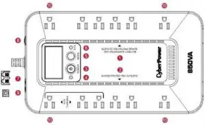
- EC650LCD (8 outlets) EC850LCD (12 outlets)
- EC450G / EC550G (8 outlets) EC750G (12 outlets)
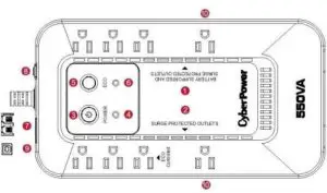
- Battery and Surge Protected Outlets
The unit has battery powered/surge suppression outlets to ensure temporary uninterrupted operation of your equipment during a power failure. (DO NOT plug a laser printer, paper shredder, copier, space heater, vacuum cleaner, sump pump, or other large electrical device into the “Battery and Surge Protected Outlets.” The power demands of these devices will overload and possibly damage the unit.) - Full-Time Surge Protection Outlets / ECO Controlled Outlets
The unit has surge suppression outlets to provide surge and line noise protection. Three of the surge-only outlets are also ECO controlled outlets. - Power Switch To turn the UPS ON, press the power button for approximately 2 seconds – you will hear a constant tone (1 second) – and release after a short beep. To turn the UPS OFF, press the power button for approximately 2 seconds – you will hear a constant tone (1 second) – and release after two short beeps. Alarm setting: The audible alarm can be turned Off or On by quickly pressing the POWER button twice. The default setting is for the Alarm On. To turn the Alarm Off, quickly press the power button twice. You will hear two short beeps when the Alarm is turned Off. To turn the Alarm back On, quickly press the power button twice. You will hear a single short beep when the Alarm is turned On. *When the Alarm is turned Off, there will be no audible notification when the UPS reaches a low battery state.
- Power On Indicator (green)
This LED is illuminated when the utility power is normal and the UPS outlets are providing power, free of surges and spikes. - Mode Switch (EC650LCD and EC850LCD only) Press the Mode Switch for approximately 3 seconds to enter setup mode to select four functions: Utility High Voltage Range, Utility Low Voltage Range, ECO ON/OFF, and LCD sleep ON/OFF. When a function is selected, press Mode Switch for 3 seconds to view options. When an option is selected, wait for 8 seconds for the setting to be confirmed. After the setting has been confirmed the LCD screen will leave setup mode and go back to status display. If there is no action for 8 seconds during setup, the LCD will also leave setup mode and go back to the status display. a. Utility High Voltage Range: Adjust the value of high voltage range. b. Utility Low Voltage Range: Adjust the value of low voltage range. c. ECO: Eon/EoF (ON/OFF): Turn on or turn off ECO function. For more information, refer to ECO Function Setup section. d. LCD: L1/L0 (ON/OFF): * When LCD is set to L1, LCD will be always ON. When LCD is set to L0, LCD will dim if untouched for 1 minute. * In battery mode, LCD is always on regardless if the setting is L1 or L0. ECO Button (EC450G, EC550G, and EC750G only) Press ECO button for 3 seconds to turn on or turn off ECO function in line mode.
- ECO Indicator
ECO Indicator shows the condition of ECO function. For more information, refer to ECO Function Setup section. - Communication Protection Ports
Communication protection ports will protect any standard modem, fax, or telephone line. (RJ11) - Circuit Breaker
Located on the side of the UPS, the circuit breaker serves to provide overload and fault protection. - USB Port to PC
The USB port allows connection and communication between the USB port on the computer and the UPS unit. The UPS communicates its status to the PowerPanel® Personal Edition software. The USB port is also used for operating the UPS in ECO mode. For more information, refer to ECO Function Setup section. - Outlets Designed for AC Adapters
The UPS unit has 4 widely-spaced outlets so AC power adapters can be plugged into the UPS without overlapping or blocking adjacent outlets.
ECO FUNCTION SETUP
ECO Function
When the ECO function is active the UPS can detect whether the PC that is connected to the USB port is turned on or off. If the PC is turned off, the UPS will turn off the ECO controlled outlets and cut power to the devices connected to them in order to save power. Generally, these are peripherals that are not used when the PC is not turned on.
ECO Controlled Outlets
Three of the surge-only outlets are also ECO controlled outlets. When the PC that is connected to the USB port is turned off, the UPS will turn off the ECO controlled outlets to save energy.
ECO Setup
- The factory default setting is OFF. ECO mode can only be enabled/disabled and will only be active when the UPS is receiving utility power and not in battery mode.
- For the EC650/850LCD, press the Mode switch for approximately 3 seconds to enter setup mode and select the ECO function. When the ECO function is selected, press the Mode switch for 3 seconds to turn the function ON or OFF. Once ON or OFF is selected, wait 8seconds for the setting to be confirmed and the LCD screen will return to status mode. For the EC450/550/750G, press the ECO button for 3 seconds to turn ON or OFF the ECO function
- When the ECO function is OFF, utility power from the ECO outlets will always be on. When the ECO function is ON, utility power from the ECO outlets will turn off if the PC connected to the UPS via the USB port is turned off or if there is no PC is connected to the UPS via USB.
ECO Indicator
The LED will be blinking when the ECO function is turned ON but the PC is either off or not connected. The LED will be solid if the ECO
function is turned on and the connected PC is on. The LED is off when the ECO function is disabled. See below table for more information.
| ECO Indicator | ECO Function | ECO Outlet Status | Condition |
| Solid (green) | ON | With Utility Power | When PC is ON and USB port on the UPS is connected, Peripherals will receive power to operate. |
| Blinking | ON | Without Utility Power | When PC is OFF or the USB port on the UPS is not connected, power to the Peripherals will be turned off. |
| OFF | OFF | Always with Utility Power | When PC is ON/OFF, Peripherals is always ON. |
DEFINITIONS FOR ILLUMINATED LED INDICATORS
 Power ON Power ON |
 Alarm |
CONDITION |
| On | Off | Normal |
| On | Beep twice every 30 seconds | Utility Failure- The UPS is providing power to battery power-supplied outlets from its battery. |
| On | Rapid Beeping every 1/2 second | Utility Failure- The UPS is providing battery power. Rapid beeping indicates the unit will run out of power shortly. |
| Off | Constant tone | Battery Overload – Occurs when connected equipment exceeds the listed capacity of the UPS. Turn the UPS off, unplug at least one piece of equipment from battery outlets, wait 10 seconds, reset the circuit breaker and turn the unit on. |
DEFINITIONS FOR ILLUMINATED LCD INDICATORS
INPUT voltage meter: This meter measures the AC voltage that the UPS system is receiving from the utility wall outlet. The UPS is designed to continuously supply connected equipment with stable output voltage. In the event of a complete power loss, severe brownout, or over-voltage, the UPS relies on its internal battery to supply consistent 110/120 output voltage. The INPUT voltage meter can be used as a diagnostic tool to identify poor-quality input power.
OUTPUT voltage meter: This meter measures, in real time, the AC voltage that the UPS system is providing to the computer during normal AC/Utility Power mode, and battery backup mode.
ESTIMATE RUN TIME: This displays the run time estimate of the UPS with the current battery capacity and load.
NORMAL icon: This icon appears when the UPS is working under normal conditions.
BATTERY icon: During a severe brownout or blackout, this icon appears and an alarm sounds (two short beeps followed by a pause) to indicate the UPS is operating from its internal battery. The alarm will continue to sound during a prolonged brownout or blackout. The BATT.CAPACITY meter will show one 20% capacity segment remaining to indicate the UPS’s battery is nearly out of power. You should save files and turn off your equipment immediately.
The LCD display indicates a variety of UPS operational conditions. All descriptions apply when the UPS is plugged into an AC outlet and turned on or when the UPS is on battery.
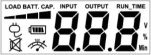
OVER LOAD icon: This icon appears and an alarm sounds to indicate the battery-supplied outlets are overloaded. To clear the overload, unplug some of your equipment from the battery-supplied outlets until the icon turns off and the alarm stops.
BATT. CAPACITY meter: This meter displays the approximate charge level of the UPS’s internal battery in 20% increments. During a blackout or severe brownout, the UPS switches to battery power (the BATTERY icon appears) and the battery charge level decreases.
LOAD CAPACITY meter: This meter displays the approximate output load level of the UPS battery outlets in 20% increments.
TROUBLESHOOTING
| Problem | Possible Cause | Solution |
| Full-time surge protection outlets stop providing power to equipment. Circuit breaker button is projecting from the side of the unit. | Circuit breaker has been tripped due to an overload. | Turn the UPS off and unplug at least one piece of equipment. Wait 10 seconds, reset the circuit breaker by pressing the button, and then turn the UPS on. |
| The UPS does not perform expected runtime. | Battery not fully charged. | Recharge the battery by leaving the UPS plugged in. |
| Battery is worn out. | Contact CyberPower Systems about replacement batteries at [email protected]. | |
| The UPS will not turn on. | The on/off switch is designed to prevent damage from rapidly turning it off and on. | Turn the UPS off. Wait 10 seconds and then turn the UPS on. |
| The unit is not connected to an AC outlet. | The unit must be connected to a 110/120V 50/60Hz outlet. | |
| The battery is worn out. | Contact CyberPower Systems about replacement batteries at [email protected]. | |
| Mechanical problem. | Contact CyberPower Systems at [email protected]. | |
| The frequency is outside of the operating range of 47-63Hz. | Turn the UPS off. Make sure the frequency range is within 47-63Hz. Or you can turn the UPS on in battery mode. | |
| PowerPanel® Personal Edition is inactive (all icons are gray). | The USB cable is not connected. | Connect the USB cable to the UPS unit and an open USB port on the computer. |
| The USB cable is connected to a bad USB port. | Check for a different USB port and plug the cable in. | |
| The unit is not providing battery power. | Shutdown your computer and turn the UPS off. Wait 10 seconds and turn the UPS back on. This should reset the unit. |
Additional troubleshooting information can be found at “Support” at
www.CPSww.com
TECHNICAL SPECIFICATIONS
| Model | EC450G | EC550G | EC750G | EC650LCD | EC850LCD |
| Capacity | 450VA/260W | 550VA/330W | 750VA/450W | 650VA/390W | 850VA/510W |
| Nominal Input Voltage | 120Vac | ||||
| Input Frequency | 47 Hz to 63 Hz | ||||
| On-Battery Output Voltage | 120Vac ± 5% | ||||
| On-Battery Output Frequency | 50Hz/60Hz ± 1% (auto-sensing) | ||||
| Max. Load for UPS Outlets | 450VA/260W | 550VA/330W | 750VA/450W | 650VA/390W | 850VA/510W |
| Max. Load for Full-Time Surge Protection outlets | 10 Amps | ||||
| On-Battery Output Wave Form | Simulated Sine Wave | ||||
| Operating Temperature | 32°F to 104° F / 0° C to 40° C | ||||
| Operating Relative
Humidity |
0 to 90% non-condensing | ||||
| Size (W x H x D) | 5.9” x 3.1” x 10.6”
150 x 79 x 269 mm |
5.9” x 3.1” x 10.6”
150 x 79 x 269 mm |
7” x 3.1” x 12.2”
178 x 79 x 310 mm |
5.9” x 3.1” x 10.6”
150 x 79 x 269 mm |
7” x 3.1” x 12.2”
178 x 79 x 310mm |
| Net Weight | 4.5 lbs / 2.1kg | 6.0 lbs / 2.7kg | 7.7 lbs / 3.5kg | 6.4 lbs / 2.9kg | 7.7 lbs / 3.5kg |
| Typical Battery Recharge Time | 8 hours typical from total discharge | ||||
| Typical Battery Life | 3 to 6 years, depending on number of discharge/recharge cycles | ||||
| Battery | Sealed Maintenance Free Lead Acid Battery | ||||
| Safety Approvals | UL1778(UPS), cUL CSA C22.2 No.107.3-05, FCC/DoC Class B | ||||
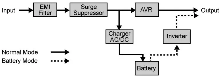
SYSTEM FUNCTION BLOCK DIAGRAM
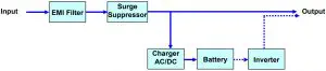
- Normal Mode

- Battery Mode

CYBERPOWER GREENPOWER UPS™ TECHNOLOGY
Advanced Energy-Saving Design
The GreenPower UPS™ has a high-efficiency charger, which makes it the most energy-efficient UPS in its class. The advanced high-frequency charging system significantly improves charging efficiency and conserves energy. As a result of this advanced design, the GreenPower UPS™ uses less energy compared to competitive models. The GreenPower UPS™ is manufactured in accordance with the Restriction on Hazardous Substances (RoHS) directive making it one of the most environmentally-friendly UPS on the market today.

Limited Warranty and Connected Equipment Guarantee
Read the following terms and conditions carefully before using the CyberPower EC450G, EC550G, EC750G, EC650LCD, and EC850LCD (the “Product”). By using the Product you consent to be bound by and become a party to the terms and conditions of this Limited Warranty and Connected Equipment Guarantee (together referred to as this “Warranty”). If you do not agree to the terms and conditions of this Warranty, you should return the Product for a full refund prior to using it.
Who is Providing this Warranty?
CyberPower Systems (USA), Inc. (“CyberPower”) provides this Limited Warranty.
What Does This Warranty Cover?
This warranty covers defects in materials and workmanship in the Product under normal use and conditions. It also covers equipment that was connected to the Product and damaged because of the failure of the Product.
What is the Period of Coverage?
This warranty covers the Product for three years. Connected equipment is covered for as long as you own the Product.
Who Is Covered?
This warranty only covers the original purchaser. Coverage ends if you sell or otherwise transfer the Product.
How Do You Get Service?
- Call us at (877) 297-6937 or write to us at Cyber Power Systems (USA), Inc., 4241 12th Ave. E., STE 400, Shakopee, MN 55379 or send us an e-mail message at [email protected] for instructions.
- When you contact CyberPower, identify the Product, the Purchase Date, and the item(s) of Connected Equipment. Have information on all applicable insurance or other resources of recovery/payment that are available to the Initial Customer andRequest a Claim Number.
- You must provide a dated Proof-of-Purchase receipt (or other proof of the original purchase) and provide a description of the defect.
How Do You Open A Connected Equipment Claim?
- Call us at (877) 297-6937 or write to us at Cyber Power Systems (USA), Inc., 4241 12th Ave. E., STE 400, Shakopee, MN 55379, or send us an e-mail message at [email protected] for instructions, within 10 days of the occurrence.
- When you contact CyberPower, identify the Product, the Purchase Date, and the item(s) of Connected Equipment. Have information on all applicable insurance or other resources of recovery/payment that are available to the Initial Customer and Request a Claim Number.
- You must provide a dated purchase receipt (or other proof of the original purchase) and provide a description of the damage to your connected equipment.
- Pack and ship the product to CyberPower and, if requested, the item(s) of Connected Equipment, a repair cost estimate for the damage to the Connected Equipment, and all claim forms that CyberPower provides to you. Show the Claim Number on the shipping label or include it with the product. You must prepay all shipping costs, you are responsible for packaging and shipment, and you must pay the cost of the repair estimate.
How Long Do I Have To Make A Claim?
All claims must be made within ten days of the occurrence.
What Will We Do To Correct Problems?
CyberPower will inspect and examine the Product.
If the Product is defective in material or workmanship, CyberPower will repair or replace it at CyberPower’s expense, or, if CyberPower is unable to or decides not to repair or replace the Product (if defective) within a reasonable time, CyberPower will refund you the full purchase price you paid for the Product (purchase receipt show in price paid is required).
If it appears that our Product failed to protect any equipment plugged into it, we will also send you forms for making your claim for the connected equipment. We will repair or replace the equipment that was damaged because of the failure of our Product or pay you the fair market value (NOT REPLACEMENT COST) of the equipment at the time of the damage. We will use Orion Blue Book, or another third-party valuation guide, or eBay, craigslist, or other source to establish that amount. Our maximum liability is limited to $100,000 for the EC450G, EC550G, EC750G, EC650LCD, and EC850LCD.
Who Pays For Shipping?
We pay when we send items to you; you pay when you send items to us.
What isn’t covered by the warranty?
- This Warranty does not cover any software that was damaged or needs to be replaced due to the failure of the Product or any data that is lost as a result of the failure or the restoration of data or records, or the re installation of software
- This Warranty does not cover or apply to: misuse, modification, operation or storage outside environmental limits of the Product or the equipment connected to it, nor for damage while in transit or in storage, nor if there has been improper operation or maintenance, or use with items not designed or intended for use with the Product, such as laser printers, appliances, aquariums, medical or life support devices, etc.
What are the Limitations?
The sole and exclusive remedies to the Initial Customer are those provided by this Warranty.
- This Warranty does not apply unless the Product and the equipment that was connected to it were connected to properly wired and grounded outlets (including compliance with electrical and safety codes of the most current electrical code), without the use of any adapters or other connectors.
- The Product must have been plugged directly into the power source and the equipment connected to the Product must be directly connected to the Product and not “daisy-chained” together in serial fashion with any extension cords, another Product or device similar to the Product, surge suppressor, or power tap. Any such installation voids the Limited Warranty
- The Product and equipment connected to it must have been used properly in a suitable and proper environment and in conformance with any license, instruction manual, or warnings provided with the Product and the equipment connected to it.
- The Product must have been used at all times within the limitations on the Product’s VA/Watt capacity.
The Product was designed to eliminate disrupting and damaging effects of momentary (less than 1ms) voltage spikes or impulses from lightning or other power transients. If it can be shown that a voltage spike lasting longer than 1ms has occurred, the occurrence will be deemed outside the rated capabilities of the Product and the Limited Warranty is void. CyberPower Does Not Cover or Undertake Any Liability in Any Event for Any of the Following:
- Loss of or damage to data, records, or software or the restoration of data or records, or the reinstallation of software.
- Damage from causes other than AC Power Line Transients, spikes, or surges on properly installed, grounded and code-compliant 120 volt power lines in the United States and Canada; transients, surges or spikes on standard telephone land lines, PBX telephone equipment lines or Base 10T Ethernet lines, when properly installed and connected. (This exclusion applies, for example, to fluctuations in data transmission or reception, by CATV or RF transmission or fluctuations, or by transients in such transmission.)
- Damage from any circumstance described as excluded above with respect to the Product.
- Damages from fire, flood, wind, rain, rising water, leakage or breakage of plumbing, abuse, misuse or alteration of either the product or the Connected Equipment.
- CyberPower excludes any liability for personal injury under the Limited Warranty and Connected Equipment Guarantee. CyberPower excludes any liability for direct, indirect, special, incidental or consequential damages, whether for damage to or loss of property [EXCEPT FOR (AND ONLY FOR) the specific limited agreement of CyberPower to provide certain warranty benefits regarding “Connected Equipment” under this Warranty], loss of profits, business interruption, or loss of information or data. NOTE: Some States or Provinces do not allow the exclusion or limitation of incidental or consequential damages, so the above limitation may not apply to you.
- The Product is not for use in high-risk activities or with aquariums. The Product is not designed or intended for use in hazardous environments requiring fail-safe performance, or for use in any circumstance in which the failure of the Product could lead directly to death, personal injury, or severe physical or property damage, or that would affect operation or safety of any medical or life support device (collectively, “High Risk Activities”). CyberPower expressly disclaims any express or implied warranty of fitness for High Risk Activities or with aquariums. CyberPower does not authorize use of any Product in any High Risk Activities or with Aquariums. ANY SUCH USE IS IMPROPER AND IS A MISUSE OF THE PRODUCT.
The application of the United Nations Convention of Contracts for the International Sale of Goods is expressly excluded. CyberPower is the warrantor under this Limited Warranty.
Where Can I Get More Information?
For further information please feel free to contact CyberPower at Cyber Power Systems (USA), Inc. 4241 12th Ave E., STE 400, Shakopee, MN 55379; call us at (877) 297-6937; or send us an e-mail message at [email protected].
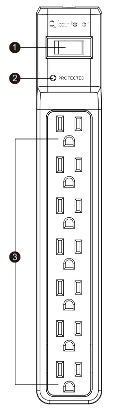
]]>![]() 7-Outlet Surge Protector
7-Outlet Surge Protector
CSB706/CSB7012
CONGRATULATIONS ON YOUR PURCHASE
Thank you for selecting the CyberPower CSB706/CSB7012 Surge Protector. This manual explains the features and operation of the CSB706/CSB7012. Please take a few moments to read this manual.
FEATURES
- ON/OFF Reset Control Switch and Circuit Breaker Control power to all outlets. The switch is also a 15 A breaker. When an overload occurs, it will automatically switch off. To resume operation, ensure the overload condition is removed and reset the surge protector by switching the unit ON.
- Surge Protected Indicator
Illuminated when the surge protection feature is
working properly. - Seven Standard Outlets
SPECIFICATIONS
- Model Number: CSB706/CSB7012
- Outlets: 7 Standard Outlets
- Surge Protection: 1500 Joules
- Electrical Rating: 125 V/15 A/1875 W UL Clamping Voltage: UL 1449 3rd/500 V (H-N, H-G, N-G)
- Maximum Peak Current: 60,000 A
- 3 AC Lines Protected: H-N: 30,000 A, H-G: 15,000 A, N-G: 15,000 A
- Response Time: Less than 1 nanosecond
- Attenuation: Up to 32 dB
- Circuit Breaker: Resettable 15 Amp
- EMI/RFI Filtration: 150 kHz to 100 MHz
CAUTION
TO REDUCE THE RISK OF ELECTRIC SHOCK – Use only in dry locations and only indoors. DO NOT plug into another relocatable power tap. DO NOT “daisy chain” surge protectors. DO NOT use any aquarium equipment. DO NOT use if properly grounded outlets are not available. DO NOT install this device if there is less than 10 meters (30 feet) or more wire between the electrical outlet and electrical service panel. DO NOT use for medical or life support equipment. This device features internal protection that will disconnect the surge protective component at the end of its useful life, but it will maintain unprotected power to the load.
TROUBLESHOOTING
- If the ON/OFF is switched OFF, the 15 Amp circuit breaker may have tripped. Examine your connected equipment and remove the device that is overloading the circuit. Then, turn the ON/OFF switch back to RESET.
- If the protected indicator does not light, the surge protector’s AC lines are no longer protected from the surge. The surge protector may have received a power surge or spike beyond its specified limits that overloaded the protection circuitry and rendered it inactive. The surge protector has protected your connected equipment as designed, but it will not protect against future surges, and spikes. It should be replaced.
TECHNICAL SUPPORT
Please contact our Tech Support Department with installation, troubleshooting, or general product questions.
- Phone: 1-877-297-6937
- Email: [email protected]
- Hours of Operation:
- Monday – Friday 7:00am – 6:00pm CST
LIMITED WARRANTY AND CONNECTED EQUIPMENT GUARANTEE
Read the following terms and conditions carefully before using the CyberPower CSB706/CSB7012 (the “product”). By using the product, you consent to be bound by the terms and conditions of this limited warranty and connected equipment guarantee (together referred to as this “warranty”).
IF YOU DO NOT AGREE TO THE TERMS AND CONDITIONS OF THIS WARRANTY, YOU SHOULD RETURN THE PRODUCT FOR A FULL REFUND PRIOR TO USING IT.
Who is providing this warranty, and what does it cover?
Cyber Power Systems (USA), Inc. (“CyberPower”) provides this limited warranty. It only covers the original purchaser and ends if you no longer own the product. This warranty covers defects in materials and workmanship in the product under normal use and conditions. It also covers equipment connected to the product damaged because of the failure of the product. This warranty covers the product and connected equipment for as long as you own the product.
How do you open a connected equipment claim?
- Call us at (877) 297-6937, or write to us at Cyber Power Systems (USA), Inc., 4241 12th Ave. E., STE 400, Shakopee, MN 55379, or
send us an email at [email protected] within 10 days of the occurrence for instructions. - When you contact CyberPower, identify the product, the purchase date, and the item(s) of connected equipment. Have information on all applicable insurance or other resources of recovery/payment that are available to the initial customer, and request a claim number.
- You must provide a dated purchase receipt (or other proof of the original purchase) for the CyberPower unit and connected equipment. You also need to provide a description of the damage to your connected equipment.
- Pack and ship the product to CyberPower and the item(s) of connected equipment, a repair cost estimate for the damage to the connected equipment, and all claim forms that CyberPower provides to you. Show the claim number on the shipping label, or include it with the product. You must prepay all shipping costs. You are responsible for packaging and shipment, and you must pay the cost of the repair estimate.
What will CyberPower do to correct problems?
CyberPower will inspect and examine the product. If the product is defective in material or workmanship, CyberPower will replace it at CyberPower’s expense, or CyberPower will refund the full purchase price you paid for the product (purchase receipt showing the price paid is required). If the product failed to protect any equipment plugged into it, we will also send you forms for making your claim for the connected equipment. We will replace the equipment that was damaged because of the failure of the product or pay you the fair market value (NOT REPLACEMENT COST) of the equipment at the time of the damage. We will use Orion Blue Book, another third-party valuation guide, eBay, Craigslist, or another source to establish that amount. Our maximum liability is limited to $125,000 for the CSB706/CSB7012.
Who pays for shipping?
We pay to ship when we send items to you; you pay when you send items to us.
What are some things this Warranty does not cover?
- THIS WARRANTY DOES NOT COVER ANY SOFTWARE THAT WAS DAMAGED, SOFTWARE THAT NEEDS TO BE REPLACED DUE TO THE FAILURE OF THE PRODUCT, OR ANY DATA THAT IS LOST AS A RESULT OF THE FAILURE. THIS WARRANTY DOES NOT COVER THE RESTORATION OF DATA OR RECORDS OR THE REINSTALLATION OF SOFTWARE.
- This warranty does not cover misuse, modification, operation, or storage outside of the environmental limits of the product or the equipment connected to it. It does not cover damage while in transit or in storage; if there has been improper operation or maintenance, or use with items not designed or intended for use with the product, such as laser printers, appliances, aquariums, medical, or life support devices, etc.
What are the other limitations?
The sole and exclusive remedies of the initial customer are those provided by this warranty.
- This warranty does not apply unless the product and the connected equipment were connected to properly wired and grounded outlets (including compliance with electrical and safety codes of the most current electrical code), without the use of any adapters or other connectors.
- The product must have been plugged directly into the power source. The equipment connected to the product must be directly connected in the product, not “daisy-chained” together in serial fashion with any extension cords, another product, or device similar to the product, surge suppressor, or power tap. Any such installation voids the warranty.
- The product and connected equipment must have been used properly in a suitable environment, in conformance with any applicable license, instruction manual, or warnings.
- The product must have been used at all times within the limitations of the product’s VA capacity.
Where can I get more information?
Contact us at:
Cyber Power Systems (USA), Inc.
4241 12th Avenue East Suite 400
Shakopee, MN 55379;
Call us at (877) 297-6937;
Send us an email at [email protected].
PRODUCT REGISTRATION
Prompt product registration assures coverage under the limited warranty, and also allows the opportunity of notifications for product enhancements, upgrades, and other announcements. Registration is quick and easy. Go to the Product Registration Page at www.cyberpowersystems.com/registration.
CONTACT INFORMATION
Cyber Power Systems (USA), Inc.
4241 12th Avenue East Suite 400
Shakopee, MN 55379
Toll-free: 1-877-297-6937
CyberPowerSystems.com

Please join CyberPower in caring for the environment by recycling this manual.

This device is manufactured using environmentally safe procedures in compliance with the Restriction of Hazardous Substances (RoHS) directive.

UL Listed to U.S. and Canadian Safety Standards UL 1449. This product is listed to applicable U.S. and Canadian safety standards by Underwriters Laboratories Inc.
Full compliance with RoHS.
© 2018 Cyber Power Systems (USA), Inc. All rights reserved.
All other trademarks are the property of their respective owners.
CyberPowerSystems.com
IMPORTANT SAFETY WARNINGS
This manual contains important instructions that should be followed during installation and maintenance of the UPS and batteries. Please read
and follow all instructions carefully during installation and operation of the unit. Read this manual thoroughly before attempting to unpack, install,
or operate.
CAUTION! The UPS must be connected to a grounded AC power outlet with fuse or circuit breaker protection. DO NOT plug the UPS into an outlet that is not grounded. If you need to de-energize this equipment, turn off and unplug the UPS.
CAUTION! DO NOT USE FOR MEDICAL OR LIFE SUPPORT EQUIPMENT! CyberPower Systems does not sell products for life support or medical applications. DO NOT use in any circumstance that would affect operation or safety of any life support equipment, with any medical applications, or patient care.
CAUTION! The battery can energize hazardous live parts inside even when the AC input power is disconnected.
CAUTION! For pluggable equipment, the socket-outlet shall be installed near the equipment and shall be easily accessible.
CAUTION! To prevent the risk of fire or electric shock, install in a temperature and humidity controlled indoor area, free of conductive contaminants. (Please see specifications for acceptable temperature and humidity range).
CAUTION! To reduce the risk of electric shock, do not remove the cover, except to service the battery. There are no serviceable parts inside, except for the battery.
CAUTION! To avoid electrical shock, turn off the unit and unplug it from the AC power source before servicing the battery or installing a computer component.
CAUTION! DO NOT USE WITH OR NEAR AQUARIUMS! To reduce the risk of fire, do not use with or near aquariums. Condensation from the aquarium can come in contact with metal electrical contacts and cause the machine to short out.
CAUTION! For model PR3000LCDRT2U and PR3000LCDRTXL2U use in a computer room as defined in the standard for the Protection of Electronic Computer/Data Processing Equipment, ANSI/NFPA 75.
INSTALLING YOUR UPS SYSTEM
UNPACKING
Inspect the UPS upon receipt. The box should contain the following. UPS Unit; (1) User’s Manual for UPS; Rack Mount Brackets; (1) Metal Stand Plate; Emergency Power Off Cable (gray); PowerPanel® Business Edition Software CD; Serial Interface Cable (DB-9); USB A+B Type Cable; Warranty Registration Card; Rubber Buffer.
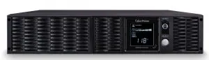
OVERVIEW
The PR3000LCDRT2U/PR3000LCDRTXL2U provides battery backup, automatic voltage regulation (AVR), and optimal performance of computers and other network equipment by ensuring consistent sinewave power. The PR3000LCDRT2U/PR3000LCDRTXL2U features 1874 Joules of surge protection, and provides battery backup during power outages. The PR3000LCDRT2U/PR3000LCDRTXL2U ensures consistent power to your computer system and its included software will automatically save your open files and shutdown your computer system during a utility power loss.
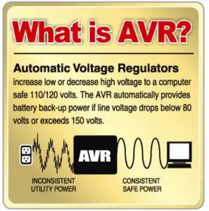
AUTOMATIC VOLTAGE REGULATOR(AVR)
The PR3000LCDRT2U/PR3000LCDRTXL2U stabilizes inconsistent utility power. The incoming utility power may be damaging to important data and hardware, but with Automatic Voltage Regulation, the computer will not experience damaging voltage levels. An Automatic Voltage Regulator automatically increases low or decreases high voltage to a consistent, computer safe 110V/120V. The unit powerful sealed lead-acid batteries will provide power only if the incoming voltage drops below 80V or increases above 150V.
SYSTEM BLOCK DIAGRAM
HARDWARE INSTALLATION GUIDE
- Your new UPS may be used immediately upon However, recharging the battery for at least four hours is recommended to ensure that the battery’s maximum charge capacity is achieved. Charge loss may occur during shipping and storage. To recharge the battery, simply leave the unit plugged into an AC outlet. The unit will charge in both the on and off position.
- If you plan to use the included software, connect either the serial cable or the USB cable to the corresponding port on the UPS and the computer. Note: if the USB port is used the serial port will be disabled. To control multiple computers install PowerPanel® Business Edition Agent on the computer connected with the USB cable and PowerPanel® Business Edition Slave on the remaining computers.
- With the UPS unit off and unplugged, connect your computer, monitor, and any externally powered data storage device (Hard drive, Tape drive, ) into the battery power supplied outlets. DO NOT plug a laser printer, copier, space heater, vacuum, paper shredder or other large electrical device into the UPS. The power demands of these devices will overload and possibly damage the unit.
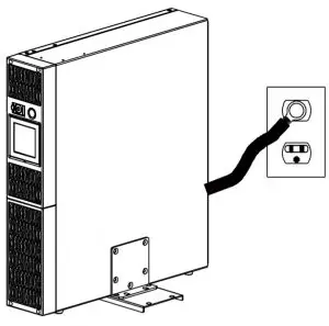
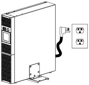
- Plug the UPS into a 2 pole, 3 wire grounded receptacle (wall outlet). Make sure the wall branch outlet is protected by a fuse or circuit breaker and does not service equipment with large electrical demands (e.g. air conditioner, refrigerator, copier, ). Avoid using extension cords.
- Depress the power switch to turn the unit on. The Power On indicator light will illuminate. If an overload is detected, an audible alarm will sound and the unit will emit one long beep. To correct this, turn the UPS off and unplug at least one piece of equipment from the battery power supplied outlets. Wait 10 seconds. Make sure the circuit breaker is depressed and then turn the UPS on.
- Your UPS is equipped with an auto-charge When the UPS is plugged into an AC outlet, the battery will automatically recharge.
- To maintain optimal battery charge, leave the UPS plugged into an AC outlet at all times.
- To store your UPS for an extended period, cover it and store with the battery fully charged. Recharge the battery every three months to ensure battery life.
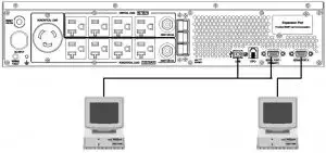
- Professional Rack Mount UPS provide one serial port, one dry contact port, and one USB port to allow communication between the UPS and computers or equipment. The dry contact port (Serial Port II) signals information for equipment that can utilize a dry contact UPS. The primary computer, with PowerPanel® Business Edition installed, connected to Serial Port I or the USB port is the computer that you use to control the UPS. When there is a power failure, the primary computer which connects to Serial Port I or the USB port will start to shutdown after a user controlled delay. PowerPanel® Business Edition Agent software will save and close any open files prior to shutting the system down and signal any configured slaves to shutdown.
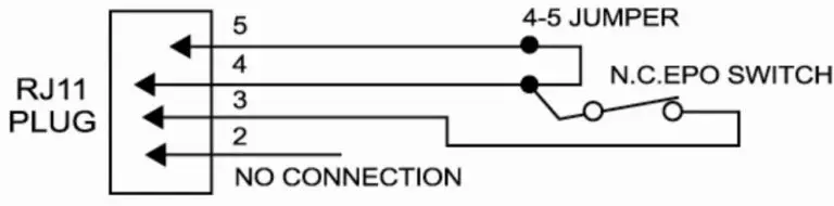
- EPO (Emergency Power Off) Port:
The feature is used with EPO controllers. Use the provided gray cable to connect to an EPO contact switch. Follow the appropriate circuit diagram below to wire the cable to match your EPO configuration. EPO function is provided in the UPS. EPO remote switch which is a Push-Back button installed computer room outside by a EPO cable, and not connected any other equipment.
Option1: user supplied normally closed switch
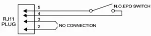
Option2: user supplied normally Open switch
 Dry connect is controlled by the PowerPanel® Software. Please go to www.cyberpowersystems.com for free download.
Note: Both USB and Serial can not be used simultaneously.
- Install PowerPanel® Business Edition software on the primary computer connected to UPS with either a serial cable or USB cable.
- The equipment can read information from dry contact.
When you first receive the unit, plug in the unit to fully charge the battery.
Unplug the unit and turn Power Off when first connecting your computer and peripherals.

BASIC OPERATION
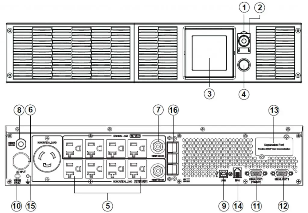
FRONT / REAR PANEL DESCRIPTION
- Power Switch
Master on/off switch for equipment connected to the UPS. - Power On Indicator
Indicates the power is on. - LCD Module Display
LCD shows all the UPS information with icons and messages. - LCD Display Toggle Button
The button can be used to toggle between different data displays on the LCD. - Battery Backup Protected Outlets Provides eight battery powered, surge protected and AVR outlets for connected equipment and ensures temporary uninterrupted operation of connected equipment during a power failure.
Critical /Non-critical
When the UPS is overloaded, the circuit breakers will be tripped to interrupt the power supply to the uncritical outlets while continuing to supply the critical outlets. As well, as the battery capacity depletes under the threshold value, the uncritical outlets will be shut down and provide energy for critical outlets. The threshold can be determined and set by users. Non-critical outlets can also be turned on/off manually through the software package provided. - Input Power Cord
Heavy-duty, extra long power cord. - Output Circuit Breaker Resettable circuit breakers provide output outlets protection from overload.
- Input Circuit Breaker
Resettable circuit breakers provide Input optimal overload
Protection. - USB port.
USB communication port for management software. - Site Wire Fault Indicator
This LED will illuminate to warn the user that a wiring problem f illuminated, disconnect all equipment and contact an electrician to ensure outlet is properly wired. - Serial Port I
Serial port allows connection and communication between the UPS and the computer. - Serial Port II
Serial Port II relays information to equipment that can utilize a contact closure UPS. - SNMP/HTTP Network slot
Remove the cover panel to install optional RMCARD that allows remote
monitoring and control of your UPS on a network - EPO (Emergency Power Off) Port:
The EPO interface enables connection to an EPO master - Ground Stud
Use the Ground Stud to ground the UPS. - External Battery Pack Connector:
Provides a connection for additional CyberPower external battery packs for extended runtime.
BATTERY REPLACEMENT
Contact your dealer, or email [email protected]. Refer to replacement battery pack number RB1290X4F for PR3000LCDRT2U /PR3000LCDRTXL2U. For model PR3000LCDRT2U/PR3000LCDRTXL2U can support model BP48V75ART2U for external battery pack. Read and follow the IMPORTANT SAFETY INSTRUCTIONS before servicing the battery. Service the battery under the supervision of personnel knowledgeable of batteries and their precautions. Servicing the battery should only be performed by trained personnel. Replacement of batteries located in an OPERATOR ACCESS AREA.
CAUTION! When replacing batteries, replace with the same number of the following battery: HR9-12FR(BB) for PR3000LCDRT2U /PR3000LCDRTXL2U.
CAUTION!
For model PR3000LCDRT2U can be provided with a maximum of five extension battery packs.
CAUTION!
Risk of energy hazard, 12V, maximum 8 Ampere-hour battery (HR9-12FR). Before replacing batteries, remove conductive jewelry such as chains, wrist watches, and rings. High energy through conductive materials could cause severe burns.
CAUTION!
Risk of battery explosion, if battery is replaced by an incorrect type. Dispose of used battery according to the instructions.
CAUTION!
To reduce the risk of fire, connect only to a circuit provided with 30 amperes maximum branch circuit overcurrent protection in accordance with the National Electric Code, ANSI/NFPA 70.
CAUTION!
Use only the specified CyberPower replacement battery, or battery pack. See your dealer for details.
CAUTION!
The battery may present a risk of electrical shock. Do not dispose of batteries in a fire, as they may explode. Follow all local ordinances regarding proper disposal of batteries.
CAUTION!
Do not open or mutilate the batteries. Released electrolyte is harmful to the skin and eyes and may be toxic.
CAUTION!
A battery may present a high risk of short circuit current and electrical shock.
Take the following precautions before replacing the battery:
- Remove all watches, rings or other metal objects.
- Only use tools with insulated
- Do not lay tools or metal parts on top of battery or any
- Wear rubber gloves and
- Determine if the battery is inadvertently grounded. If inadvertently grounded, remove source of ground. CONTACT WITH A GROUNDED BATTERY CAN RESULT IN ELECTRICAL SHOCK! The likelihood of such shock will be reduced if such grounds are removed during installation and maintenance (applicable to a UPS and a remote battery supply not having a grounded circuit).
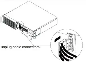
BATTERY REPLACMENT PROCEDURE:
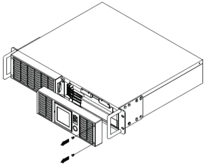
- Remove two screws and front panel on the right side.
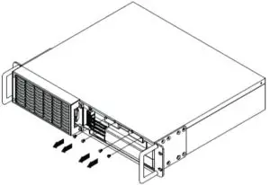
- Remove the four retaining screws of the cable protection cover then remove the cover.
- unplug cable connectors.
- Pull out the old battery pack and replace new one.
Reassemble the retaining screws, covers, black and red cable, and front panel in the reverse sequence of the above steps. Recharge the unit for 4-8 hours to ensure maximum UPS battery runtime.
LCD STATUS DEFINITION
INPUT voltage meter: This meter measures the AC voltage that the UPS system is receiving from the utility wall outlet. The INPUT voltage readout can be used as a diagnostic tool to identify poor-quality input power. The AVR in this UPS continuously conditions the power to a stable 110/120V output to connected equipment. In the event of a complete power loss, severe brownout, or over voltage, the UPS relies on its internal battery back up to supply a consistent 110/120V output.
OUTPUT voltage meter:
This meter measures in real time, the AC voltage that the UPS system is providing to the computer, such as normal line mode, AVR mode and battery back up mode.
Note:
The OUTPUT voltage readout displays the status of the battery back up outlets.
ESTIMATE RUN TIME:
This displays the run time estimate of the UPS with the current battery capacity
and load.
NORMAL icon:
This icon appears when the UPS is working under normal conditions.
BATTERY icon:
During a severe brownout or blackout, this icon appears and an alarm sounds (two short beeps followed by a pause) to indicate the UPS is operating from its Internal batteries. During an extended brownout or blackout that drains the battery, a continuous alarm will sound (and the BATT. CAPACITY readout will show a single shaded segment, equaling 20% battery capacity remaining) indicating the UPS batteries are nearly out of power. If this occurs, it is recommended that you save your files and manually power down your equipment immediately.
Automatic Voltage Regulation (AVR) icon:
This icon appears whenever your UPS is automatically correcting low AC input line voltage without using battery power. This is a normal, automatic operation of your UPS, and no action is required.
SILENT MODE icon:
This icon appears whenever the UPS is in silent mode. The buzzer does not beep during silent mode until the battery reaches low capacity.
OVER LOAD icon:
This icon appears and an alarm sounds to indicate the battery-supplied outlets are overloaded. To clear the overload, unplug some of your equipment from the battery-supplied outlets until the icon turns off and the alarm stops.
FAULT icon:
This icon appears if there is a problem with your UPS.
BATT. CAPACITY meter:
This meter displays the approximate charge level (in 20% increments) of the UPS’s internal battery. During a blackout or severe brownout the UPS switches to battery back up power the BATT. CAPACITY icon appears and the charge level decreases.
LOAD CAPACITY:
This meter displays the approximate output load level (in 20% increments) of the UPS’s battery outlets.
The LCD display indicates a variety of UPS operational conditions. All descriptions apply when the UPS is plugged into the AC outlet and turned on or when the UPS is on battery
LCD STATUS AND SETUP FUCTIONS
General Mode:
- Press the “Display” button to check the status of the
- Press and hold the Display toggle for 4 seconds,
If the machine is in the Battery Mode, it enters the status of Mute.
If the machine is in the Line Mode, it proceeds Self Test. - If the Display toggle remains untouched for over 30 seconds, the LCD backlight will turn off automatically
Item Unit 1 Input Voltage V 2 Output Voltage V 3 Output Frequency Hz 4 Load Kw 5 Estimate Run Time Min 6 Load Capacity % 7 Battery Capacity % 8 Centigrade ℃ 9 Fahrenheit ℉
Set-up Mode
Step 1:
The machine enters Set-Up Mode after holding the Display toggle for 10 seconds. Icon 3,4,5,6,7,8 lights to indicate Set-Up Mode.
Step 2:
By pressing the Display toggle, users can switch between setup functions. User configurable functions are as follows:
- Sensitivity: Set the level of tolerance for Increase the UPS compatibility for local utility power condition.
High: The UPS will turn to battery power more often to provide the steady power supply to the connected equipment.
Low: The UPS will tolerate more fluctuations and turn to battery power less often - Battery Pack Numbers: This function provides the estimated UPS runtime using various numbers of battery The default setting is 0
- Battery Lifetime: Show the batteries already used Reset the logger when battery module replacement or first time installation.
- Firmware Version: Show the UPS version number.
The settable items are sorted by unit as in the following table:
| Items | Unit | |
| 1 | Sensitivity | |
| 2 | Battery Pack Numbers | A |
| 3 | Battery Lifetime | Year |
| 4 | Firmware Version |
Step 3:
Press and hold the toggle for 4 seconds. When the icons blink, the value of each item can be changed by slightly pressing the toggle.
Step 4:
To save the value and return to general mode, press and hold the toggle for 4 seconds.
Note:
If the machine is left idle for over 30 seconds during setup, it will turn off the backlight and return to general mode automatically.
Note:
If user wants to return to general mode without saving changes, there are two methods:
- Wait for the backlight to turn off
- Press and hold the “Display” toggle for 10 seconds
TROUBLE SHOOTIMG
| Problem | Possible Cause | Solution |
| Outlet do not provide power to equipment | Circuit breaker has tripped due to an overload. | Turn the UPS off and unplug at least one piece of equipment.
Wait 10 seconds, reset the circuit breaker by depressing the button, and then turn the UPS on. |
| Batteries are discharged | Recharge the unit for at least 4 hours | |
| Unit has been damaged by a
surge or spike. |
Contact CyberPower Systems about replacement batteries at | |
| Uncritical outlets have turned off automatically
due to an overload |
Push the toggle button to make the uncritical outlets turn on. | |
| The UPS does not perform expected runtime. | Battery not fully charged. | Recharge the battery by leaving the UPS plugged in. |
| Battery is degraded | Contact CyberPower Systems about replacement batteries at [email protected] | |
| The UPS will not turn on. | The on/off switch is designed to prevent damage by rapidly
turning it off and on. |
Turn the UPS off. Wait 10 seconds and then turn the UPS on. |
| The unit is not connected to an AC outlet. | The unit must be connected to a 110/120V outlet. | |
| The battery is worn out. | Contact CyberPower Systems about replacement batteries at [email protected] | |
| Mechanical problem. | Contact CyberPower Systems at [email protected] | |
| PowerPanel® Personal Edition is inactive | The serial cable or USB cable is not connected. | Connect the cable to the UPS unit. You must use the cable that came with the unit. |
| The cable is connected to the wrong port. | Try another port of your computer | |
| The unit is not providing battery power. | Shutdown your computer and turn the UPS off. Wait 10 seconds and turn the UPS back on. This should reset
the unit. |
|
| The serial cable is not the cable that was provided
with the unit. |
You must use the cable included with the unit for the software |
Additional troubleshooting information can be found at www.cyberpowersystems.com/support.htm
TECHNICAL
| Model | PR3000LCDRT2U | PR3000LCDRTXL2U |
| Capacity(VA) | 3000 | 3000 |
| Capacity(Watts) | 2700 | 3000 |
| Input | ||
| Input Plug Type | NEMA 5-30P | |
| Input Voltage Range | 80Vac-150Vac | |
| Input Frequency Range | 50/60Hz+/-3Hz(auto sensing) | |
| Output | ||
| On Battery Output Voltage | Pure Sine Wave at 120Vac+/-5% | |
| On Battery Output Frequency | 50/60Hz+/-1% | |
| Transfer Time(Typical) | 4 ms | |
| Overload Protection | On Utility: Circuit Breaker, On Battery: Internal Current Limiting | |
| Surge Protection and Filtering | ||
| Lightning/Surge Protection | Yes | |
| Physical | ||
| Output Receptacles | (8)NEMA 5-15/20R+(1)NEMA 5-30R | |
| Dimensions(in) | 2U Rack, 17.1’’ x 19.7’’ x 3.5’’ | |
| Weight (lb) | 79 | 71 |
| Battery | ||
| Battery Model | RB1290X4F | |
| Extension Runtime | Yes(Only Five Battery Pack) | Yes |
| Hot Swappable External Battery | Yes | |
| Warning Diagnostics | ||
| Indicators | Power On, Wiring Fault, LCD Display (Using Battery, AVR, Load Level, Battery Level) | |
| Audible Alarms | On Battery, Low Battery, Overload | |
| Environmental | ||
| Operating Temperature | 32oF to 104oF ( 0oC to 40 oC ) | |
| Operating Relative Humidity | 0 to 95% Non-Condensing | |
| Operating Elevation | 0-10000 feet (0-3000 meters) | |
| Communication | ||
| PowerPanel ®Business Edition | Windows 98/ME/NT/2000/XP/Vista/7 | |
| Management | ||
| Self-Test | Manual Self-Test | |
| Auto-Charger/ Auto-Restart | Yes | |
| COM Interface | True RS232 x1+ Dry connector x1 | |
| Built-in USB Interface | Yes | |
| SNMP/ HTTP Network Slot | Yes | |
| Safety Approvals | UL1778,cUL107,FCC Part 15 Class A,CSA | |
CYBERPOWER GREENPOWER UPS™ TECHNOLOGY
Green power UPS
The CyberPower GreenPower UPS™ cuts UPS energy costs by up to 75% compared to the conventional UPS circuits. Conventional UPS systems pass power through a transformer to provide normal output voltage to protected devices. By contrast, the GreenPower UPS™ circuitry bypasses the transformer when utility power is normal, significantly increasing the power efficiency of the UPS. As a result, a GreenPower UPS™ produces less heat and uses less energy reducing energy costs.
When utility power is abnormal, the GreenPower UPS™ operates like a normal UPS. Since utility power operates normally 88% of the time, the GreenPower UPS™ operates primarily in its cost-cutting bypass mode.
LIMITED WARRANTY AND CONNECTED EQUIPMENT GUARNTEE
Read the following terms and conditions carefully before using the CyberPower PR3000LCDRT2U/PR3000LCDRTXL2U (the “Product”). By using the Product you consent to be bound by and become a party to the terms and conditions of this Limited Warranty and Connected Equipment Guarantee (together referred to as this “Warranty”). If you do not agree to the terms and conditions of this Warranty, you should return the Product for a full refund prior to using it.
Who is Providing this Warranty?
CyberPower Systems (USA), Inc. (“CyberPower”) provides this Limited Warranty.
What Does This Warranty Cover?
This warranty covers defects in materials and workmanship in the Product under normal use and conditions. It also covers equipment that was connected to the Product and damaged because of the failure of the Product.
What is the Period of Coverage?
This warranty covers the Product for three years and connected equipment for as long as you own the Product.
Who Is Covered?
This warranty only covers the original purchaser. Coverage ends if you sell or otherwise transfer the Product.
How Do You Get Service?
- Call us at (877) 297-6937 or write to us at Cyber Power Systems (USA), , 4241 12th Ave. E., STE 400, Shakopee, MN 55379 or send us an e-mail message at [email protected] for instructions.
- When you contact CyberPower, identify the Product, the Purchase Date, and the item(s) of Connected Equipment. Have information on all applicable insurance or other resources of recovery/payment that are available to the Initial Customer and Request a Claim
- You must provide a dated Proof-of-Purchase receipt (or other proof of the original purchase) and provide a description of the
- Pack and ship the product with a dated Proof- of-Purchase receipt to CyberPower and, if requested, the item(s) of Connected Equipment, a repair cost estimate for the damage to the Connected Equipment, and all claim forms that CyberPower provides to Show the Claim Number on the shipping label or include it with the product. You must prepay all shipping costs, you are responsible for packaging and shipment, and you must pay the cost of the repair estimate.
How Long Do I Have To Make A Claim?
All claims must be made within ten days of the occurrence.
What Will We Do To Correct Problems?
CyberPower will inspect and examine the Product.If the Product is defective in material or workmanship, CyberPower will repair or replace it at CyberPower’s expense, or, if CyberPower is unable to or decides not to repair or replace the Product (if defective) within a reasonable time, CyberPower will refund to you the full purchase price you paid for the Product (purchase receipt showing price paid is required).
If it appears that our Product failed to protect any equipment plugged into it, we will also send you forms for making your claim for the connected equipment. We will repair or replace the equipment that was damaged because of the failure of our Product or pay you the fair market value (NOT REPLACEMENT COST) of the equipment at of the time of the damage. We will use Orion Blue Book, or another a third-party valuation guide, or eBay, craigslist, or other source to establish that amount. Our maximum liability is limited to $400,000 for PR3000LCDRT2U/PR3000LCDRTXL2U.
Who Pays For Shipping?
We pay when we send items to you; you pay when you send items to us.
What Are Some Things This Warranty Does Not Cover?
- This Warranty does not cover any software that was damaged or needs to be replaced due to the failure of the Product or any data that is lost as a result of the failure or the restoration of data or records, or the re installation of
- This Warranty does not cover or apply to: misuse, modification, operation or storage outside environmental limits of the Product or the equipment connected to it, nor for damage while in transit or in storage, nor if there has been improper operation or maintenance, or use with items not designed or intended for use with the Product, such as laser printers, appliances, aquariums, medical or life support devices,
What Other Limitations Apply?
- This Warranty does not apply unless the Product and the equipment that was connected to it were connected to properly wired and grounded outlets (including compliance with electrical and safety codes of the most current electrical code), without the use of any adapters or other
- The Product must have been plugged directly into the power source and the equipment connected to the Product must be directly connected to the Product and not “daisy-chained” together in serial fashion with any extension cords, another Product or device similar to the Product, surge suppressor, or power Any such installation voids the Limited Warranty.
- The Product and equipment connected to it must have been used properly in a suitable and proper environment and in conformance with any license, instruction manual, or warnings provided with the Product and the equipment connected to it.
- The Product must have been used at all times within the limitations on the Product’s VA capacity.
What are the Limitations?
The sole and exclusive remedies of the Initial Customer are those provided by this Warranty.
The Product was designed to eliminate disrupting and damaging effects of momentary (less than 1ms) voltage spikes or impulses from lightning or other power transients. If it can be shown that a voltage spike lasting longer than 1ms has occurred, the occurrence will be deemed outside the rated capabilities of the Product and the Limited Warranty is void. CyberPower Does Not Cover or Undertake Any Liability in Any Event for Any of the Following:
- Loss of or damage to data, records, or software or the restoration of data or records, or the reinstallation of
- Damage from causes other than AC Power Line Transients, spikes, or surges on properly installed, grounded and code-compliant 120 volt power lines in the United States and Canada; transients, surges or spikes on standard telephone land lines, PBX telephone equipment lines or Base 10T Ethernet lines, when properly installed and connected. (This exclusion applies, for example, to fluctuations in data transmission or reception, by CATV or RF transmission or fluctuations, or by transients in such transmission.)
- Damage from any circumstance described as excluded above with respect to the
- Damages from fire, flood, wind, rain, rising water, leakage or breakage of plumbing, abuse, misuse or alteration of either the product or the Connected
- CyberPower excludes any liability for personal injury under the Limited Warranty and Connected Equipment Guarantee. CyberPower excludes any liability for direct, indirect, special, incidental or consequential damages, whether for damage to or loss of property [EXCEPT FOR (AND ONLY FOR) the specific limited agreement of CyberPower to provide certain warranty benefits regarding “Connected Equipment” under this Warranty], loss of profits, business interruption, or loss of information or data. NOTE: Some States or Provinces do not allow the exclusion or limitation of incidental or consequential damages, so the above limitation may not apply to you.
- The Product is not for use in high-risk activities or with The Product is not designed or intended for use in hazardous environments requiring fail-safe performance, or for use in any circumstance in which the failure of the Product could lead directly to death, personal injury, or severe physical or property damage, or that would affect operation or safety of any medical or life support device (collectively, “High Risk Activities”). CyberPower expressly disclaims any express or implied warranty of fitness for High Risk Activities or with aquariums. CyberPower does not authorize use of any Product in any High Risk Activities or with Aquariums. ANY SUCH USE IS IMPROPER AND IS A MISUSE OF THE PRODUCT.
What is the Fine Print?
The application of the United Nations Convention of Contracts for the International Sale of Goods is expressly excluded. CyberPower is the warrantor under this Limited Warranty.
For further information please feel free to contact CyberPower at Cyber Power Systems (USA), Inc. 4241 12th Ave E., STE 400, Shakopee, MN 55379; call us at (877) 297-6937; or send us an e-mail message at [email protected].
Recycle Policy
CyberPower Systems encourages environmentally sound methods for disposal and recycling of its UPS products. Please dispose and/or recycle your UPS and batteries in accordance to the local regulations of your state.
FCC Notice
This device complies with part 15 of the FCC Rules. Operation is subject to the following two conditions: (1) This device may not cause harmful interference, and (2) this device must accept any interference received, including interference that may cause undesired operation.
WARNING!! This equipment has been tested and found to comply with the limits for a Class A digital device, pursuant to part 15 of the FCC Rules. These limits are designed to provide reasonable protection against harmful interference when the equipment is operated in a commercial environment. This equipment generates, uses, and can radiate radio frequency energy and, if not installed and used in accordance with the instruction manual, may cause harmful interference to radio communications. Operation of this equipment in a residential area is likely to cause harmful interference in which case the user will be required to correct the interference at his own expense. Shielded signal cables must be used with this product to ensure compliance with the Class A FCC limits.
The Class A digital apparatus meets all requirements of the Canadian Interference-Causing Equipment Regulation.