DAIKIN ONE+ Smart Thermostat User Manual
![]()
DAIKIN ONE+ SMART THERMOSTAT Homeowner Guide
Everything you expect in a smart thermostat backed by the world’s leading HVAC manufacturer
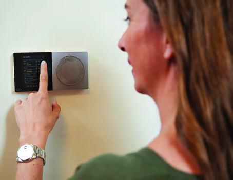
Getting Started
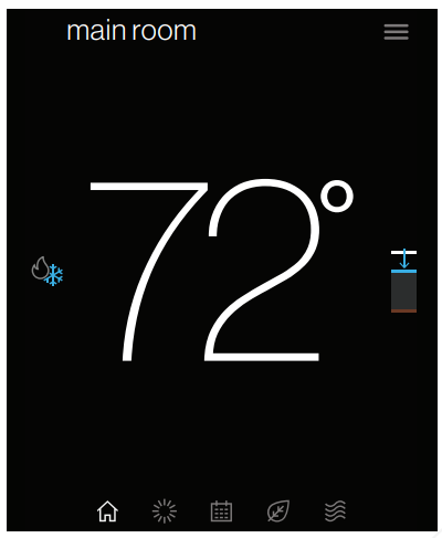
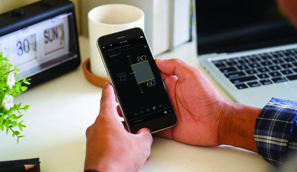
Tap the bottom navigation icons to move between the 5 main screens:

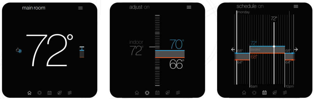
| The home screen displays the current temperature, the current system mode, and icons leading to each of the top-level screens. | The adjusted screen displays the current temperature on the left and set points on the right. Change the set-points by dragging them or by turning the dial. | The schedule screen displays upcoming set-point changes and scheduled times. It also offers access to edit mode, where you can adjust the schedule. |
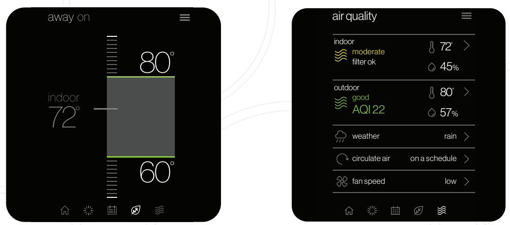
| The away screen displays energy-saving set-points. Energy-saving can be invoked manually or automatically when the mobile app recognizes everyone is away. |
The air quality screen* displays indoor air quality levels when a Daikin One home air monitor is connected. Outdoor air quality and weather will be displayed when connected to the internet and thermostat added in the mobile app under home location. |
*Actual screen may vary for different indoor unit models. The Daikin One home air monitor only works with ducted units.
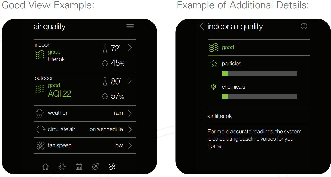
Air Quality Alert Examples* :
TO DOWNLOAD THE DAIKIN ONE HOME MOBILE APP,
SCAN THE QR CODE OR VISIT:
 WWW.DAIKINONE.COM/SMART_THERMOSTATS/ONEPLUS/APP
*Actual screen may vary for different indoor unit models. The Daikin One home air monitor only works with ducted units and is sold separately.

Mobile App
When WiFi is enabled on your Daikin One+ smart thermostat, the Daikin One Home mobile app can help you manage and remotely control multiple Daikin One+ smart thermostats in your home.
Additional Smart Features
Enabling WiFi adds smart features to your thermostat:

- Automatic software updates.
- Remote control with mobile app.
- Alerts when you are away from home.
- Voice control capabilities when connected to Amazon Alexa and/or Google Assistant devices.
- Download the Amazon Alexa or the Google Assistant app and follow the instructions within the app to set up the Daikin One+ smart thermostat voice control capabilities properly.
- Geo-fencing, to detect when you are away from home, reducing energy costs.
You can connect the Daikin One+ smart thermostat to WiFi by following these steps:
Connect to WiFi
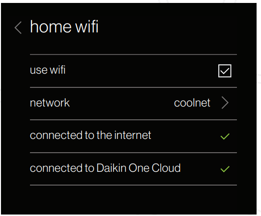
- Navigate to the settings menu.
(Tap the menu icon in the top right of the home menu and select settings.) - Tap the configuration menu » Home WiFi.
(Ensure the use WiFi box is checked.) - Tap networks » Then select your network from the list.
(You’ll be prompted to enter your network’s password and then connect.)
Pair to App
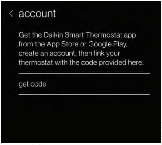 NOTE: The pairing code will expire in 15 minutes, but you can always get a new code if needed.
Thermostat Steps
- Navigate to the settings menu.
(Tap the menu icon in the top right of the home menu and select settings.) - Tap the configuration menu » Account.
- Use the code displayed to input into the app.
Connection to Amazon Alexa
Connecting Daikin One+ smart thermostat to Amazon Alexa will enable voice commands through Alexa like “Alexa, set my Kitchen to 75 degrees”
How to connect?
Complete setup on Daikin One+ smart thermostat and Daikin One Home mobile app. Login to Alexa account from phone/tablet device. Use the instructions below:
| 1. Click on the menu icon | 5. Select “Daikin One Smart Thermostat” |
| 2. Select “Skills & Games” | 6. Select “Enable to use” (This will display a Daikin sign in the window at login.daikinskyport.com) |
| 3. Click on the “Search” icon | 7. Enter Daikin One Home mobile app login credentials |
| 4. Type “Daikin”, click search | |
This will successfully link Daikin One+ smart thermostat to Amazon Alexa.
Voice Commands
- Alexa, set [my / the] {{THERMOSTAT NAME}} to (cool/ heat/auto/off).
- Alexa, set [my / the] {{THERMOSTAT NAME}} temperature] to X [degrees].
- Alexa, (increase / decrease) [my] {{THERMOSTAT NAME}} [temperature] by X [degrees].
- Alexa, (increase / decrease / lower / cool down / warm up) [the] {{THERMOSTAT NAME}}.
- Alexa, make [my] {{THERMOSTAT NAME}} (warmer /cooler).
- Alexa, what is {{THERMOSTAT NAME}} set to?
Connection to Google Home
Connecting Daikin One+ smart thermostat to Google Home will enable voice commands through Google Assistant like “Ok Google, set my bedroom to cool“.
How to connect?
Complete setup on Daikin One+ smart thermostat and Daikin One Home mobile app. Login to Google Home account from phone/tablet device
| 1. Click “Add” device | 4. Click on the search icon |
| 2. Select “Set up device” | 5. Type “Daikin One Smart Thermostat” and Select. (This will display a Daikin sign-in window at login.daikinskyport.com) |
| 3. Select “have something already set up?“ | 6. Enter Daikin One Home mobile app login credentials. |
This will successfully link Daikin One+ smart thermostat to Google Home.
Voice Commands
- Ok Google, set [my / the] {{THERMOSTAT NAME}} to (cool/heat).
- Ok Google, turn (up / down) [the] {{THERMOSTAT NAME}}.
- Ok Google, set [my / the] {{THERMOSTAT NAME}} [temperature] to X [degrees].
- Ok Google, (increase / decrease) [my] {{THERMOSTAT NAME}} [temperature] by X [degrees].
- Ok Google, (increase / decrease) [my] {{THERMOSTAT NAME}}.
- Ok Google, make [my] {{THERMOSTAT NAME}} (warmer / cooler).
- Ok Google, what is {{THERMOSTAT NAME}} set to?
DAIKIN ONE+ SMART THERMOSTAT HOMEOWNER GUIDE
How to Switch Modes
For systems that have both heating and cooling, you have the ability to choose a mode: auto (the thermostat will select the mode based on the condition and set temperature), cool (only), heat (only), or off.
| From the Home Screen Simply tap the mode icons located on the left-hand side of the current temperature. |
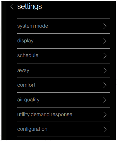
From the Settings Menu Access settings from any primary screen by tapping the menu icon. Then select system mode. |
 |
 |
How to Create a Schedule
With the Daikin One+ smart thermostat, you can create a different schedule for each mode of the thermostat. If you have both heating and cooling available to you, your thermostat will have the ability to create a schedule for Heat (only), Cool (only), and Auto mode.
- Tap on the schedule icon to
 bring up the schedule menu.
 - Tap the menu icon located in the upper right-hand corner.
- Tap the edit schedule option.
- Select the day you wish to edit by tapping the header in the upper left-hand corner.
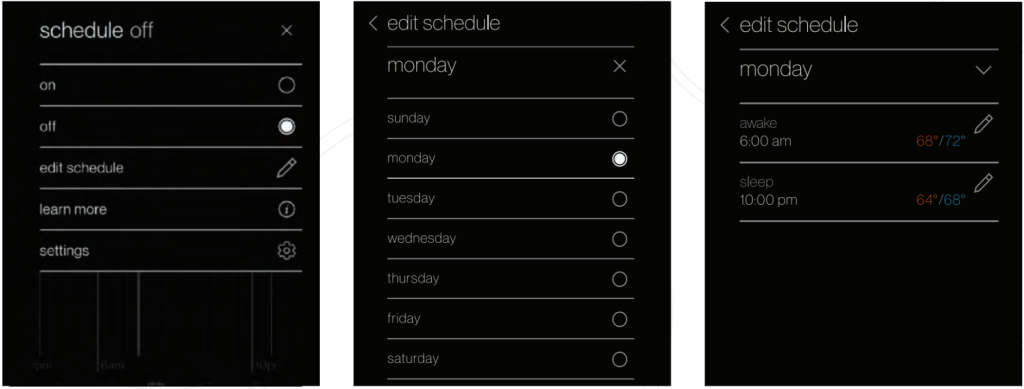
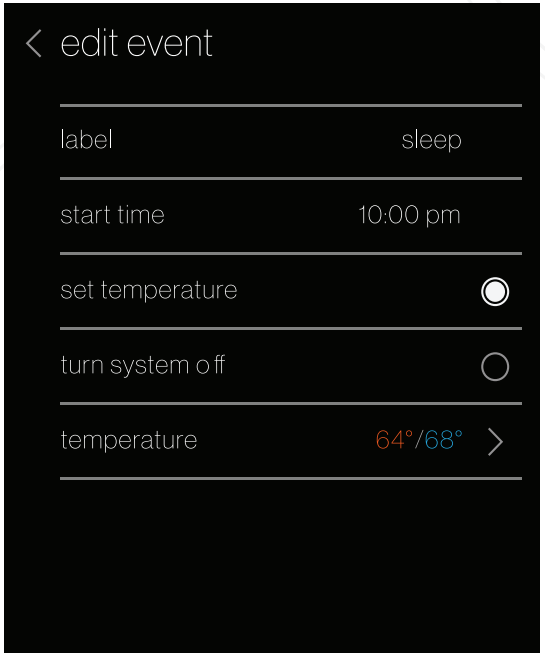
Add New or Edit Current Event
From the edit screen, tap the “Add new event” or “edit event” option located at the bottom of the screen.
- Start Time: Tap and drag the hour and minute intervals to update.
- Event Label: Edit the name of the event.
- Event Action: Choose the action you want your system to perform.
Once you’ve finished making your changes be sure to tap save, which is in the lower right-hand corner.
Copy Schedules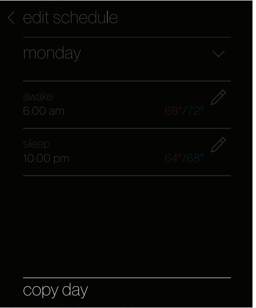 To make things easy, we’ve added an option to copy a day’s schedule.
To do this:
- Select which day you would like to copy.
- Select “copy day” on the bottom right footer.
- Choose which days to copy to.
The day being copied will be greyed out, while the days that you are copying will highlight white once selected.
Creating a Schedule from a Template
Templates can be used as the basis of a schedule that fits your lifestyle. You can also edit the schedule once you select a template. Any edits in the current schedule will be deleted when loading a template.
- Tap the menu icon in the upper right-hand corner.
- Select the settings option.
- Select schedule.
- Select schedule templates.
You can view a schedule template (see examples below) by tapping and selecting it from the list.
Customized Settings
With the Daikin One+ smart thermostat customize settings to better suit your comfort needs.
- Navigate to the settings menu
(Tap the menu icon in the top right of the home menu and select settings.) - Tap the Display option
(This will take you to the preference screen where updates can be made.)
 |
Light Bar Choose to enable or disable the light bar, used to indicate when the system is heating or cooling. |
 |
Analog Dial Sound Choose to enable or disable the haptic sound when rotating the analog dial. |
 |
Screen Savers Choose between a selection of screen savers to be displayed when the thermostat is not being interacted with. |
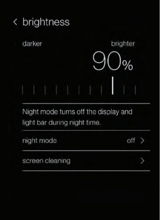
Night Mode
When enabled, night mode turns off the display and light bar during the selected schedule time.
To access this setting, tap the brightness option from the display menu.
If you encounter any issues or would like assistance with setting up your Daikin One+ smart thermostat, please contact Daikin support at 1-855-Daikin1 and select OPTION ONE to be connected with our thermostat support team.
Customized Settings continued:

Large font option
To enable, do the following:
- Open the settings by tapping the menu item in the top right and selecting “settings.”
- Navigate to display settings.
- Enable the “use large font” checkbox.

Spanish and French Language support
To choose a language do the following:
- Open the settings by tapping the menu item in the top right and selecting “settings.”
- Navigate to language settings: display > language.
- Select desired language.

Ability to restart thermostat
To restart the thermostat, do the following:
- Open the settings by tapping the menu item in the top right and selecting “settings.”
- Navigate to system settings: configuration > system components > thermostat.
- Select “restart thermostat.”
Important Notes
This device complies with Part 15 of the FCC Rules. Operation is subject to the following two conditions:
- this device may not cause harmful interference, and
- this device must accept any interference received, including interference that may cause undesired operation.
Changes or modifications not expressly approved by Daikin could void the user’s authority to operate the equipment.
This equipment has been tested and found to comply with the limits for a Class B digital device, pursuant to Part 15 of the FCC Rules. These limits are designed to provide reasonable protection against harmful interference in a residential installation. This equipment generates, uses and can radiate radio frequency energy and, if not installed and used in accordance with the instructions, may cause harmful interference to radio communications. Howeve
to radio communications. However, there is no guarantee that interference will not occur in a particular installation.
If this equipment does cause harmful interference to radio or television reception, which can be determined by turning the equipment off and on, the user is encouraged to try to correct the interference by one or more of the following measures:
- Reorient or relocate the receiving antenna.
- Increase the separation between the equipment and receiver.
- Connect the equipment into an outlet on a circuit different from that to which the receiver is connected.
- Consult the dealer or an experienced radio/TV technician for help
- Consult the dealer or an experienced radio/TV technician for help.
This device contains license-exempt transmitter(s)/receiver(s) that comply with Innovation, Science, and Economic Development Canada’s license-exempt RSS(s). Operation is subject to the following two conditions:
- This device may not cause interference.
- This device must accept any interference, including interference that may cause undesired operation of the device.
FOR ADDITIONAL RESOURCES AND INSTRUCTIONAL VIDEOS,
SCAN CODE OR VISIT:.

If you encounter any issues or would like assistance with setting up your Daikin One+ smart thermostat, please contact Daikin support at 1-855-Daikin1 and select OPTION ONE to be connected with our thermostat support team.
ADDITIONAL INFORMATION
Before purchasing this appliance, read important information about its estimated annual energy consumption, yearly operating cost, or energy efficiency rating that is available from your retailer.
Google, Google Assistant, and all related logos are trademarks of Google or its affiliates. Amazon, Alexa, and all related logos are trademarks of Amazon.com, Inc. or its affiliates.
Our continuing commitment to quality products may mean a change in specifications without notice. © 2020 DAIKIN NORTH AMERICA LLC • Houston, Texas • USA • www.daikincomfort.com or www.daikinac.com
HG-ONE+ST 08-20
FAQS
Is the Daikin One+ smart thermostat compatible with my existing HVAC system?
Yes. The Daikin One+ smart thermostat is compatible with most HVAC systems, including heat pump, air conditioning, and heat pump/air conditioning systems. The Daikin One+ smart thermostat is compatible with single-stage, two-stage, and variable-speed systems.
Will the Daikin One+ smart thermostat work with my current HVAC system?
The Daikin One+ smart thermostat is compatible with most HVAC systems, including heat pump, air conditioning, and heat pump/air conditioning systems. The Daikin One+ smart thermostat is compatible with single-stage, two-stage, and variable-speed systems.
What kind of WiFi connection does the Daikin One+ smart thermostat need to connect to my WiFi network?
The Daikin One+ smart thermostat needs an 802.11 b/g/n 2.4GHz WiFi connection to connect to your home WiFi network.
Does the Daikin One+ smart thermostat work outside of North America?
Yes. The Daikin One+ smart thermostat can be used in any country that has a power supply between 100 VAC and 240 VAC at 50/60 Hz.
Does nest work with Daikin?
Daikin products will function with the Nest Learning Thermostat and Nest Protect: Smoke + Carbon Monoxide alarm, as well as the Dropcam Wi-Fi video monitoring camera and service.
Why does my Daikin thermostat keep turning off?
When the unit stops unexpectedly, it’s usually protecting itself from voltage fluctuations, and should start working again within a few minutes. When the temperature in your room reaches the set level the unit switches to “breeze mode” to maintain the temperature.
How do you wire a Daikin one thermostat?
Connect wires 1 and 2 from the indoor unit to 1 and 2 at the outdoor unit. Wiring communicating indoor unit to non-communicating outdoor units. Connect 1, 2, C and R from the Daikin One+, to 1, 2, C and R at the indoor unit. Connect wire Y1 from the indoor unit to Y1 at the outdoor unit.
Why does my thermostat turn off by itself?
If the condenser coils in your air conditioning unit are clogged, the air will be restricted, causing the unit to overheat. And when an air conditioner overheats, it will automatically shut off due to the high limit switch. The purpose of the high limit switch is to prevent the unit from overworking for too long.
Does Daikin Mini Split have a thermostat?
Enjoy the efficiency and individual room comfort of your Daikin mini split through your phone or wall mounted thermostat.
Why is my thermostat showing the wrong temperature?
Your thermostat will read the wrong temperature if it isn’t located in your home’s most optimal place. If it’s located near drafts or heat sources, or it’s in an area that isn’t centrally located, you may need to have it moved. If you can’t fix your thermostat problems, contact an HVAC professional soonest possible.
How long is a thermostat good for?
As with any system, eventually, your thermostat will become outdated. Modern home thermostats tend to have about a 10-year lifespan but are usually replaced sooner due to innovations in the market. Non-programmable thermostats have become outdated and replaced by programmable (or learning) thermostats.
What is the Daikin one cloud?
Daikin One Cloud Services combines a cloud-based web portal and mobile app that puts the power of information into your hands, allowing you to provide your customers with high levels of service and greater peace of mind than ever before.
What is Daikin fit?
The Daikin Fit system is an inverter unit which runs continuously but adjusts the compressor’s speed to meet the demand. Because it maintains the temperature consistently, your home will no longer feel too hot or too cold.
Why is my thermostat reading higher than the setting?
A thermostat turns on your heating system by determining the temperature of its environment with a sensor. If your thermostat’s sensor isn’t functioning properly or at all, the result is a room temperature that’s either higher or lower than your thermostat setting.
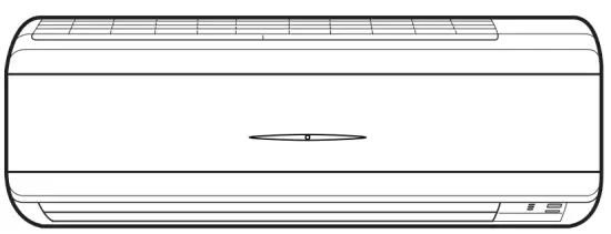
]]>DAIKIN FTXF50D2V1B Room Air Conditioner
INFORMATION
This appliance is intended to be used by expert or trained users in shops, in light industry, and on farms, or for commercial and household use by lay persons.
Documentation set
This document is part of a documentation set. The complete set consists of:
- General safety precautions:
- Safety instructions that you must read before operating your system
- Format: Paper (in the box of the indoor unit)
- Operation manual:
- Quick guide for basic usage
- Format: Paper (in the box of the indoor unit)
- User reference guide:
- Detailed step-by-step instructions and background information for basic and advanced usage
- Format: Digital files on http://www.daikineurope.com/support-and-manuals/product-information/
Latest revisions of the supplied documentation may be available on the regional Daikin website or via your installer.
The original documentation is written in English. All other languages are translations.
User Safety Instructions
Always observe the following safety instructions and regulations.
Instructions for Safe Operation
WARNING: MILDLY FLAMMABLE MATERIAL
The refrigerant inside this unit is mildly flammable.
CAUTION
Do NOT insert fingers, rods or other objects into the air inlet or outlet. When the fan is rotating at high speed, it will cause injury.
WARNING
- Do NOT modify, disassemble, remove, reinstall or repair the unit yourself as incorrect dismantling or installation may cause an electrical shock or fire. Contact your dealer.
- In case of accidental refrigerant leaks, make sure there are no naked flames. The refrigerant itself is entirely safe, non-toxic and mildly flammable, but it will generate toxic gas when it accidentally leaks into a room where combustible air from fan heaters, gas cookers, etc. is present. Always have qualified service personnel confirm that the point of leakage has been repaired or corrected before resuming operation.
CAUTION
- ALWAYS use a user interface to adjust the angle of the flap. When the flap is swinging and you move it forcibly by hand, the mechanism will break.
- Be careful when adjusting the louvers. Inside the air outlet, a fan is rotating at high speed.
CAUTION
NEVER expose little children, plants or animals directly to the airflow.
WARNING
Do NOT place a flammable spray bottle near the air conditioner and do NOT use sprays near the unit. Doing so may result in a fire.
CAUTION
Do NOT operate the system when using a room fumigation-type insecticide. Chemicals could collect in the unit, and endanger the health of people who are hypersensitive to chemicals.
WARNING
The refrigerant inside the unit is mildly flammable, but normally does NOT leak. If the refrigerant leaks in the room and comes in contact with fire from a burner, a heater, or a cooker, this may result in fire, or the formation of a harmful gas.
Turn off any combustible heating devices, ventilate the room, and contact the dealer where you purchased the unit.
Do NOT use the unit until a service person confirms that the part from which the refrigerant leaked has been repaired.
WARNING
- Do NOT pierce or burn refrigerant cycle parts.
- Do NOT use cleaning materials or means to accelerate the defrosting process other than those recommended by the manufacturer.
- Be aware that the refrigerant inside the system is odorless.
WARNING
The appliance shall be stored so as to prevent mechanical damage and in a well-ventilated room without continuously operating ignition sources (e.g. open flames, an operating gas appliance, or an operating electric heater). The room size shall be as specified in the General safety precaution.
DANGER: RISK OF ELECTROCUTION
To clean the air conditioner or air filter, be sure to stop operation and turn all power supplies OFF. Otherwise, an electrical shock and injury may result.
CAUTION
After a long use, check the unit stand and fitting for damage. If damaged, the unit may fall and result in injury.
CAUTION
Do NOT touch the heat exchanger fins. These fins are sharp and could result in cutting injuries.
WARNING
Be careful with ladders when working in high places.
WARNING
Improper detergents or cleaning procedure may cause damage on plastic components or water leakage. Splashed detergent on electric components, such as motors, may cause failure, smoke or ignition.
DANGER: RISK OF ELECTROCUTION
Before cleaning, be sure to stop the operation, turn the breaker OFF or pull out the supply cord. Otherwise, an electrical shock and injury may result.
WARNING
Stop operation and shut OFF the power if anything unusual occurs (burning smells etc.).
Leaving the unit running under such circumstances may cause breakage, electrical shock or fire. Contact your dealer.
About the System
NOTICE
Do NOT use the system for other purposes. In order to avoid any quality deterioration, do NOT use the unit for cooling precision instruments, food, plants, animals, or works of art.
Indoor Unit
CAUTION
Do NOT insert fingers, rods or other objects into the air inlet or outlet. When the fan is rotating at high speed, it will cause injury.
WARNING
- Do NOT modify, disassemble, remove, reinstall or repair the unit yourself as incorrect dismantling or installation may cause an electrical shock or fire. Contact your dealer.
- In case of accidental refrigerant leaks, make sure there are no naked flames. The refrigerant itself is entirely safe, non-toxic and mildly flammable, but it will generate toxic gas when it accidentally leaks into a room where combustible air from fan heaters, gas cookers, etc. is present. Always have qualified service personnel confirm that the point of leakage has been repaired or corrected before resuming operation.
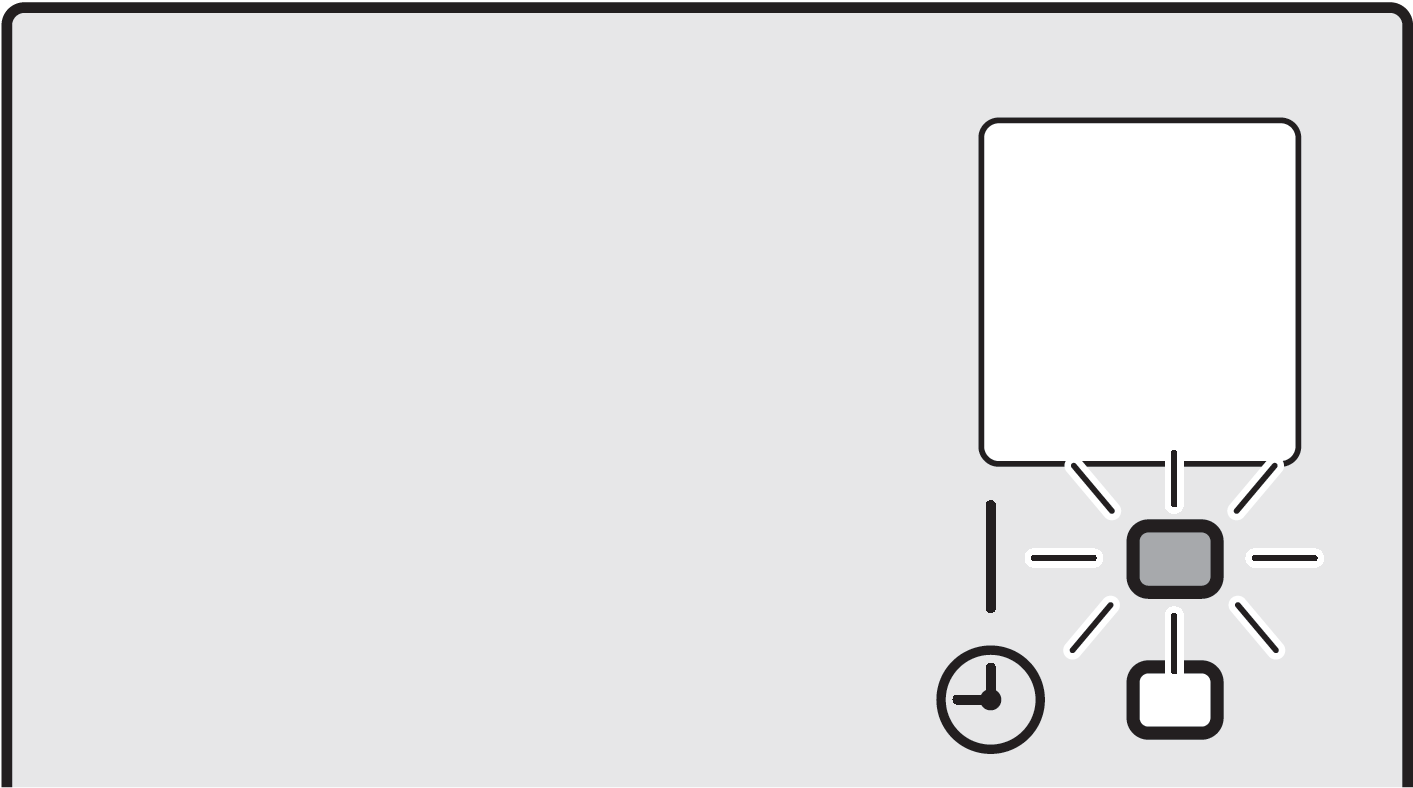
Indoor Unit Display
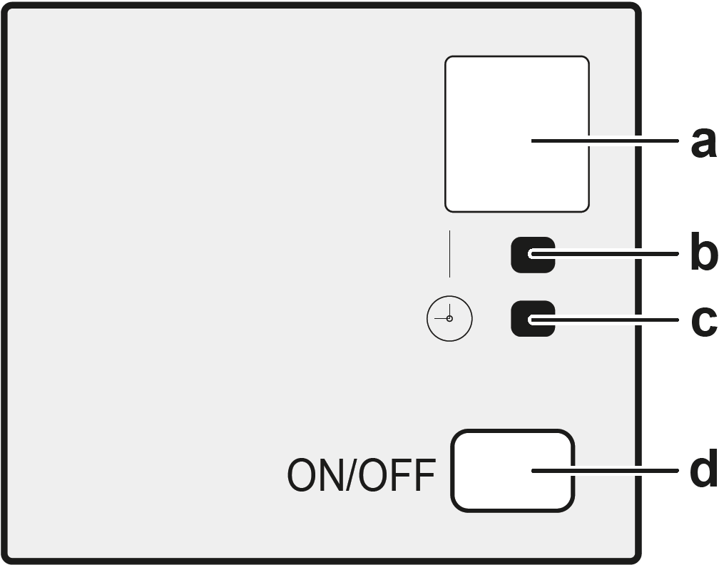
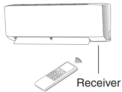
- a Signal receiver
- b Operation lamp
- c Timer lamp
- d ON/OFF button
ON/OFF Button
If the user interface is missing, you can use the ON/OFF button on the indoor unit to start/stop operation. When operation is started using this button, the following settings are used:
- Operation mode = Automatic
- Temperature setting = 25°C
- Airflow rate = Automatic
About the User Interface
- Direct sunlight. Do NOT expose the user interface to direct sunlight.
- Dust. Dust on the signal transmitter or receiver will reduce sensitivity. Wipe off dust with a soft cloth.
- Fluorescent lights. Signal communication might be disabled if fluorescent lamps are in the room. In that case, contact your installer.
- Other appliances. If the user interface signals operate other appliances, move the other appliances, or contact your installer.
- Curtains. Make sure that the signal between the unit and the user interface is NOT blocked by curtains or other objects.
Components: User Interface
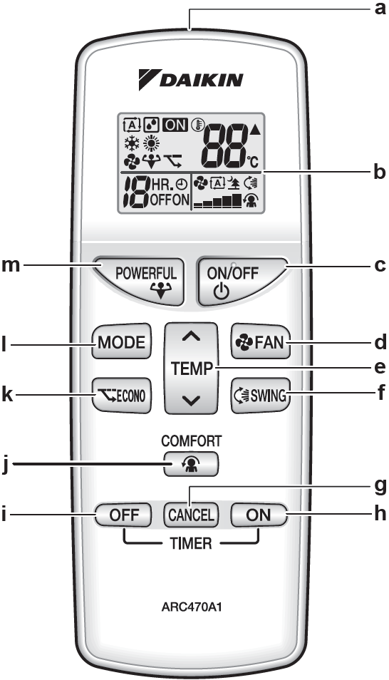
- a Signal transmitter
- b LCD display
- c ON/OFF button
- d Fan setting button
- e Temperature adjustment button
- f Swing button
- g Timer cancel button
- h ON timer button
- i OFF timer button
- j Comfort airflow button
- k Econo button
- Mode selector button
- m Powerful button
To Operate the User Interface
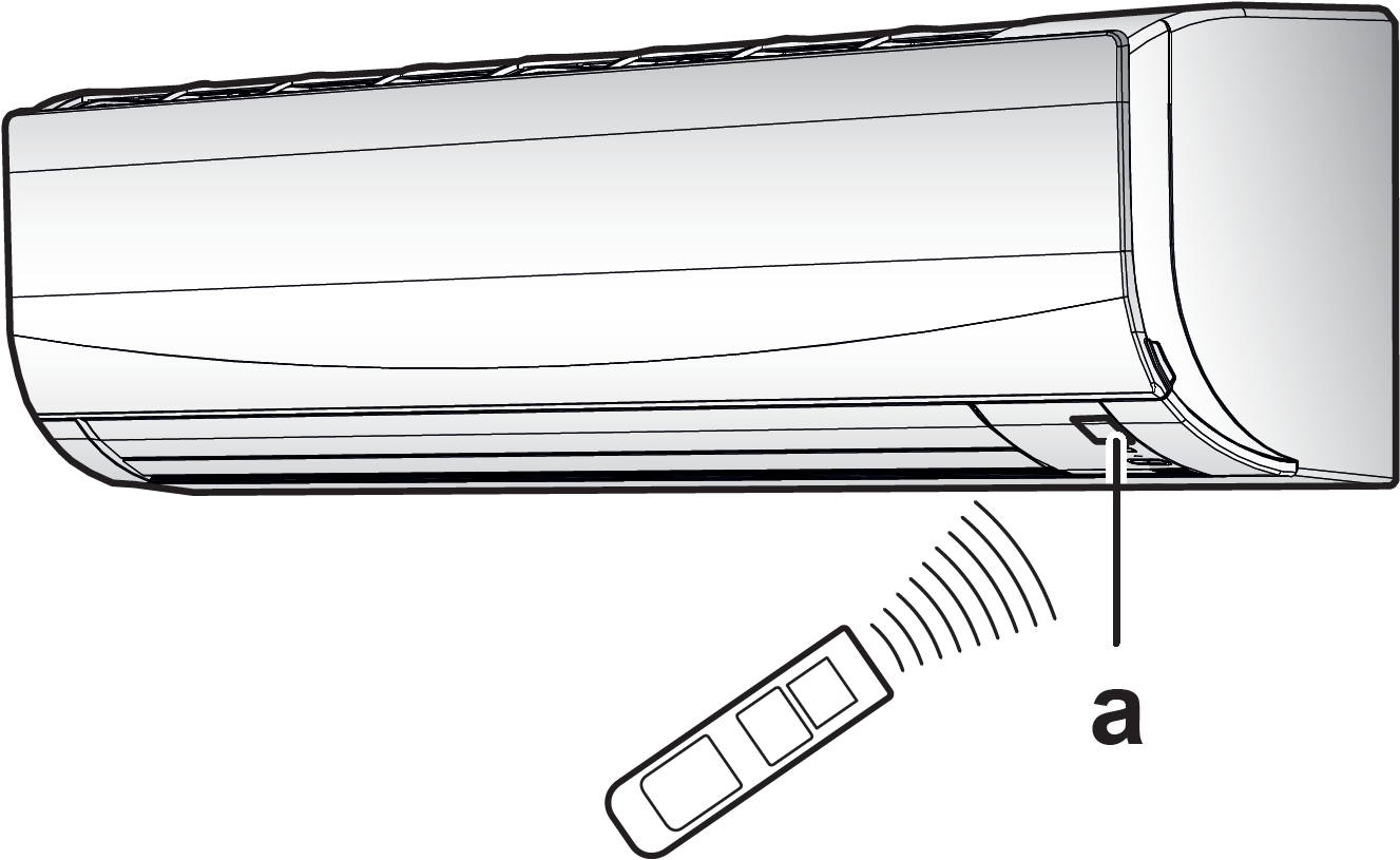
Aim the signal transmitter at the signal receiver on the indoor unit (maximum distance for communication is 7m).
Result: When the indoor unit receives a signal from the user interface, you will hear a sound:
| Sound | Description |
| Beep-beep | Operation starts. |
| Beep | Setting changes. |
| Long beep | Operation stops. |
Before Operation
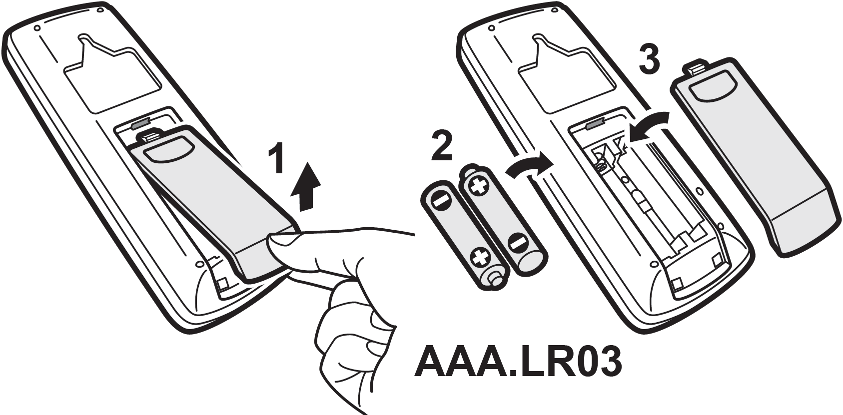
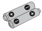
To Insert the Batteries
The batteries will last for about 1 year.
- Remove the back cover.
- Insert both batteries at once.
- Put the cover back.
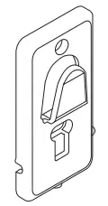
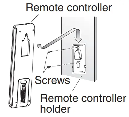
To Mount the User Interface Holder
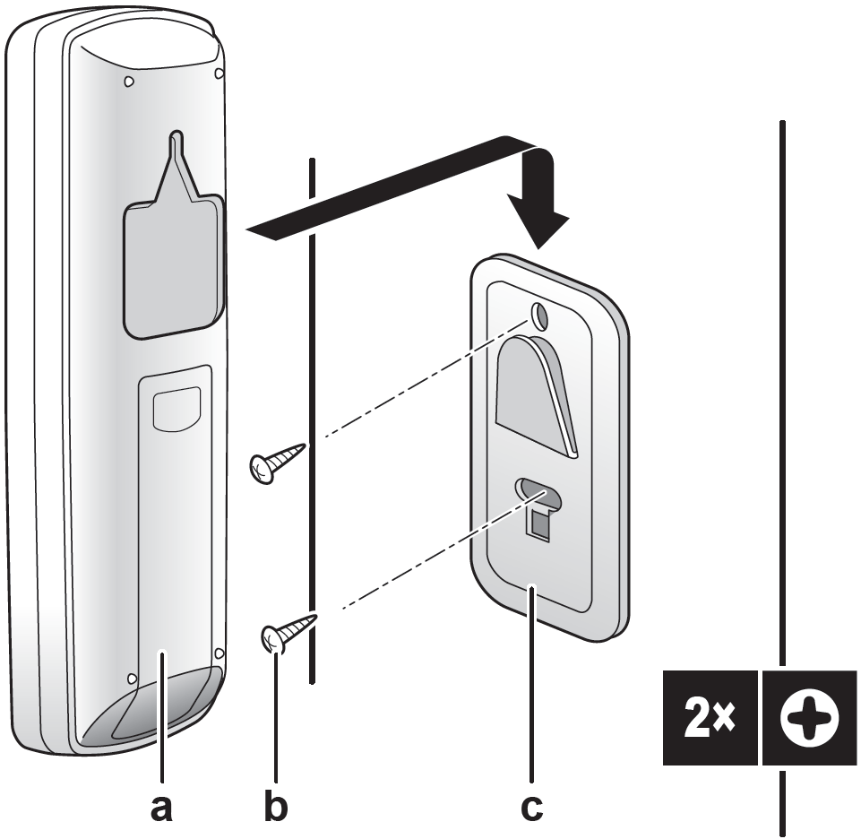
- a User interface
- b Screws (field supply)
- c User interface holder
- Choose a place where the signals reach the unit.
- Attach the holder with screws to the wall or a similar location.
- Hang the user interface on the user interface holder.
To Turn on the Power Supply
Turn the circuit breaker on.
Result: The flap of the indoor unit will open and close to set the reference position.
Operation
Operation Range
Use the system in the following temperature and humidity ranges for safe and effective operation.
| Operation Mode | Operation Range |
| Cooling(a)(b) |
|
| Heating(a) |
|
| Drying(a) |
|
(a) A safety device might stop the operation of the system if the unit runs outside its operation range.
(b) Condensation and water dripping might occur if the unit runs outside its operation range.
Operation Mode and Temperature Setpoint
When. Adjust the system operation mode and set the temperature when you want to:
- Heat up or cool down a room
- Blow air in a room without heating or cooling
- Decrease the humidity in a room
What. The system operates differently, depending on the user selection.
| Setting | Description |
| Automatic | The system cools down or heats up a room to the temperature setpoint. It automatically switches between cooling and heating if necessary. |
| Drying | The system decreases the humidity in a room. |
| Heating | The system heats up a room to the temperature setpoint. |
| Cooling | The system cools down a room to the temperature setpoint. |
| Fan | The system only controls the airflow (airflow rate and airflow direction). The system does NOT control the temperature. |
Additional info:
- Outside temperature. The system’s cooling or heating effect decreases when the outside temperature is too high or too low.
- Defrost operation. During heating operation, frost might occur on the outdoor unit and decrease the heating capacity. In that case, the system automatically switches to defrosting operation to remove the frost. During defrosting operation, hot air is NOT blown from the indoor unit.
To start/stop operation mode and to set the temperature
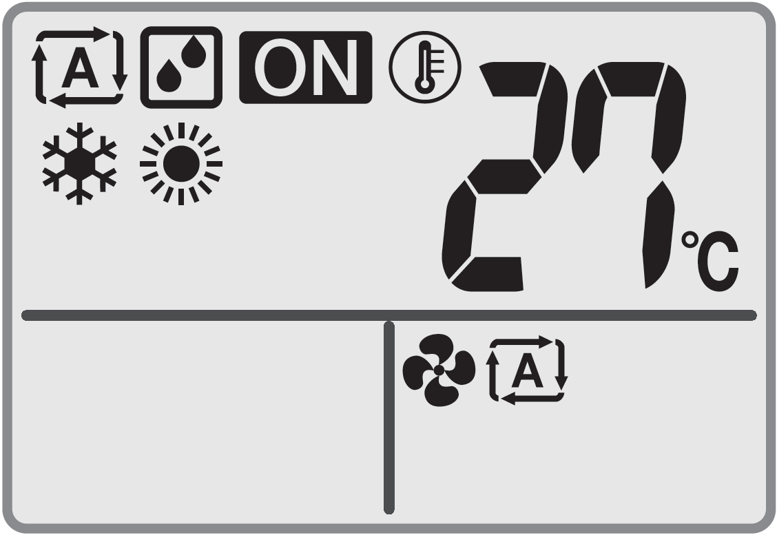
- Unit is operating
- Operation mode = Automatic
- Operation mode = Drying
- Operation mode = Heating
- Operation mode = Cooling
- Operation mode = Fan only
- Shows the set temperature
- Press MODE one or more times to select the operation mode.
Result: The mode will be set in the following sequence:

- Press ON/OFF to start operation.
Result: ON is displayed on the LCD.
Result: The operation lamp lights up.
- Press UP or DOWN on the TEMP button one or more times to lower or raise the temperature.
Note: When using drying or fan only mode, you cannot adjust the temperature. - Press ON/OFF to stop operation.
Result: ON disappears from the LCD.
Result: The operation lamp goes off.
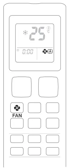
Airflow Rate
INFORMATION
- When using drying operation mode, you CANNOT adjust the airflow rate setting.
- The airflow rate in heating mode will lower to avoid generating cold airflow. When temperature of the airflow rise, operation will continue at the set airflow rate.
Press FAN to choose:
 |
5 airflow rate levels, from ” ” to “ “ |
 |
Automatic airflow rate operation |
 |
Indoor unit quiet operation. When the airflow rate is set to icon, the noise from the unit will be reduced. |
INFORMATION
- If the unit reaches the temperature setpoint in cooling or heating mode, the fan will stop operating.
- When using drying operation mode, you CANNOT adjust the airflow rate setting.
To Adjust the Airflow Rate
- Press FAN to change the airflow setting as follows:

Airflow Direction
When. Adjust the airflow direction as desired.
What. The system directs the airflow differently, depending on the user selection (swinging or fixed position). It does so by moving the vertical blades.
| Setting | Airflow Direction |
| Vertical auto swing | Moves up and down. |
| [—] | Stays in a fixed position. |
CAUTION
- ALWAYS use a user interface to adjust the angle of the flap. When the flap is swinging and you move it forcibly by hand, the mechanism will break.
- Be careful when adjusting the louvers. Inside the air outlet, a fan is rotating at high speed.
The movable range of the flap varies according to the operation mode. The flap will stop at the upper position when the airflow rate is changed to low during the up and down swing setting.
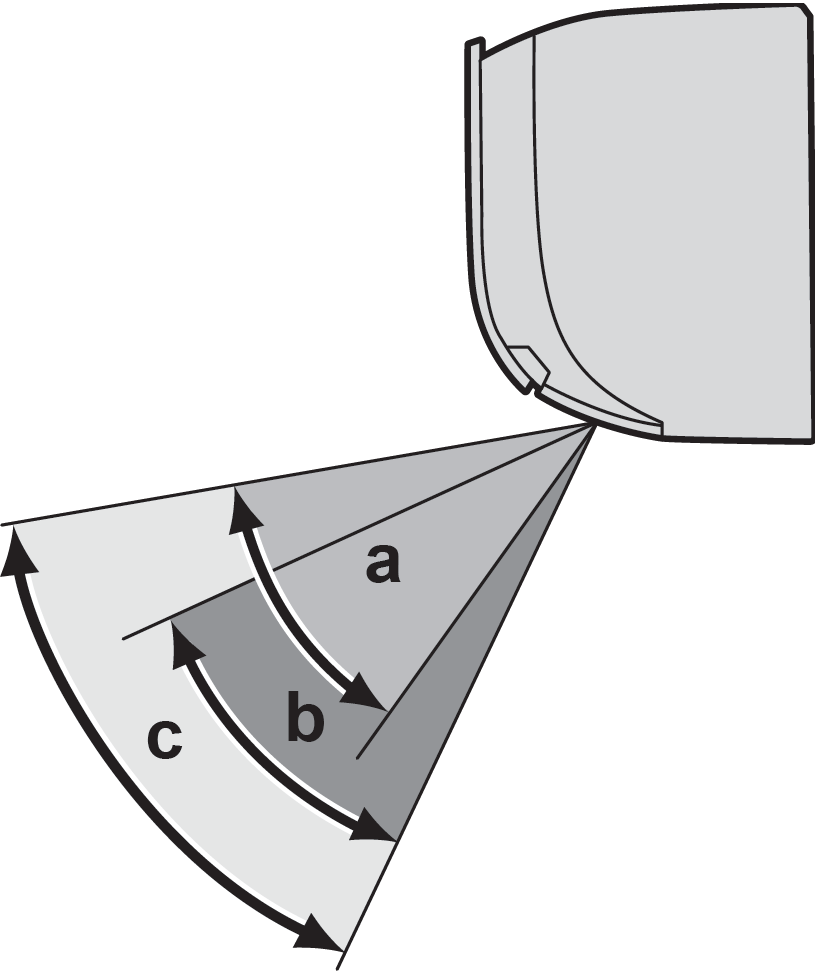
- a Flap range in cooling or drying operation
- b Flap range in hating operation
- c Flap range in fan only operation
To Adjust the Airflow Direction
- To use auto swing, press SWING.
Result: will appear on the LCD.
Result: The flap (horizontal blade) will begin to swing. - To use fixed position, press SWING when the flap reaches the desired position.
Result: disappears from the LCD.
To Adjust the Louvers (Vertical Blades)
- Hold 1 or both knobs and move the louvers.
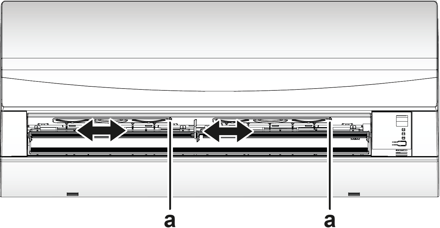
INFORMATION
When the unit is installed in a corner of a room, the direction of the louvers should be facing away from the wall. Efficiency will drop if a wall blocks the air.
Comfort Airflow Operation
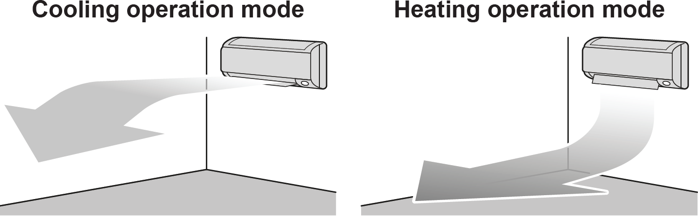
This operation can be used in heating or cooling operation mode. It will provide a comfortable wind that will NOT come in direct contact with people. The system automatically sets the fixed airflow position upward in Cooling and downward in Heating operation mode.
INFORMATION
Powerful and Comfort airflow operation CANNOT be used at the same time. The last selected function takes priority. If the vertical automatic swing is selected, Comfort airflow operation will be cancelled.
To Start/Stop Comfort Airflow Operation
- Press COMFORT to start.
Result: The flap position will change, is displayed on the LCD, and the airflow rate is set to automatic.Mode Position of flap… Cooling/Drying Up Heating Down Note: Comfort airflow operation is NOT available in Fan only mode.
- Press to stop.
Result: The flap will return to the position from before the Comfort airflow mode; disappears from the LCD.
Powerful Operation
This operation quickly maximizes the cooling/heating effect in any operation mode. You can get the maximum capacity.
INFORMATION
Powerful operation CANNOT be used together with Econo and Comfort airflow operation. The last selected function takes priority.
Powerful operation will NOT increase the capacity of the unit if it already operates at maximum capacity.+
To Start/Stop Powerful Operation
- Press POWERFUL to start.
Result: is displayed on the LCD. Powerful operation runs for 20 minutes; after that, operation returns to the previously set mode. - Press POWERFUL to stop.
Result: disappears from the LCD.
Note: Powerful operation can be set only when the unit is running. If you press ON/OFF or if you change operation mode, operation will be cancelled; disappears from the LCD.
Econo Operation
This is a function which enables efficient operation by limiting the maximum power consumption value. This function is useful for cases in which attention should be paid to ensure a circuit breaker will not trip when the product runs alongside other appliances.
INFORMATION
- Powerful and Econo operation CANNOT be used at the same time. The last selected function takes priority.
- Econo operation reduces power consumption of the outdoor unit by limiting the rotation speed of the compressor. If power consumption is already low, Econo operation will NOT further reduce power consumption.
To Start/Stop Econo Operation
- Press ECONO to start.
- Press ECONO to stop.
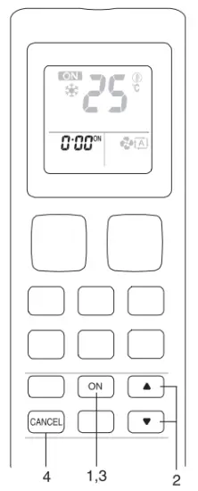
OFF/ON Timer Operation
Timer functions are useful for automatically switching the air conditioner off/on at night or in the morning. You can also use OFF timer and ON timer in combination.
To Start/Stop OFF Timer Operation
Use this feature if the unit is operating and you want to stop operation after a certain time.
- Press OFF to start.
- Press OFF to stop.
To Start/Stop ON Timer Operation
- Press OFF to start.
- Press OFF to stop.
To Combine OFF Timer and ON Timer
- To set the timers, refer to “To start/stop OFF timer operation” and “To start/stop ON timer operation”.
- Example of what is displayed on the LCD if you combine the 2 timers:

Energy Saving and Optimum Operation
INFORMATION
- Even if the unit is turned OFF, it consumes electricity.
- When the power turns back on after a power break, the previously selected mode will be resumed.
CAUTION
NEVER expose little children, plants or animals directly to the airflow.
NOTICE
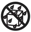
Do NOT place objects below the indoor and/or outdoor unit that may get wet. Otherwise condensation on the unit or refrigerant pipes, air filter dirt or drain blockage may cause dripping, and objects under the unit may get dirty or damaged.
WARNING
Do NOT place a flammable spray bottle near the air conditioner and do NOT use sprays near the unit. Doing so may result in a fire.
CAUTION
Do NOT operate the system when using a room fumigation-type insecticide. Chemicals could collect in the unit, and endanger the health of people who are hypersensitive to chemicals.
Maintenance and Service
Overview: Maintenance and Service
The installer has to perform a yearly maintenance.
About the Refrigerant
This product contains fluorinated greenhouse gases. Do NOT vent gases into the atmosphere.
Refrigerant type: R32
Global warming potential (GWP) value: 675
NOTICE
Applicable legislation on fluorinated greenhouse gases requires that the refrigerant charge of the unit is indicated both in weight and CO2 equivalent.
Formula to calculate the quantity in CO2 equivalent tonnes: GWP value of the refrigerant × total refrigerant charge [in kg] / 1000
Please contact your installer for more information.
WARNING
The refrigerant inside the unit is mildly flammable, but normally does NOT leak. If the refrigerant leaks in the room and comes in contact with fire from a burner, a heater, or a cooker, this may result in fire, or the formation of a harmful gas.
Turn off any combustible heating devices, ventilate the room, and contact the dealer where you purchased the unit.
Do NOT use the unit until a service person confirms that the part from which the refrigerant leaked has been repaired.
WARNING
- Do NOT pierce or burn refrigerant cycle parts.
- Do NOT use cleaning materials or means to accelerate the defrosting process other than those recommended by the manufacturer.
- Be aware that the refrigerant inside the system is odorless.
WARNING
The appliance shall be stored so as to prevent mechanical damage and in a well-ventilated room without continuously operating ignition sources (e.g. open flames, an operating gas appliance, or an operating electric heater). The room size shall be as specified in the General safety precaution.
NOTICE
Maintenance MUST be done by an authorized installer or service agent.
We recommend performing maintenance at least once a year. However, applicable legislation might require shorter maintenance intervals.
DANGER: RISK OF ELECTROCUTION
To clean the air conditioner or air filter, be sure to stop operation and turn all power supplies OFF. Otherwise, an electrical shock and injury may result.
WARNING
To prevent electrical shocks or fire:
- Do NOT rinse the unit.
- Do NOT operate the unit with wet hands.
- Do NOT place any objects containing water on the unit.
CAUTION
After a long use, check the unit stand and fitting for damage. If damaged, the unit may fall and result in injury.
CAUTION
Do NOT touch the heat exchanger fins. These fins are sharp and could result in cutting injuries.
WARNING
Be careful with ladders when working in high places.
Following symbols may occur on the indoor unit:
To Clean the Indoor Unit and User Interface
WARNING
Improper detergents or cleaning procedure may cause damage on plastic components or water leakage. Splashed detergent on electric components, such as motors, may cause failure, smoke or ignition.
NOTICE
- Do NOT use gasoline, benzene, thinner, polishing powder or liquid insecticide. Possible consequence: Discoloration and deformation.
- Do NOT use water or air of 40°C or higher. Possible consequence: Discoloration and deformation.
- Do NOT use polishing compounds.
- Do NOT use a scrubbing brush. Possible consequence: The surface finishing peels off.
- As an end user, you may NEVER clean inside parts of the unit by yourself; this work must be performed by a qualified service person. Contact your dealer.
DANGER: RISK OF ELECTROCUTION
Before cleaning, be sure to stop the operation, turn the breaker OFF or pull out the supply cord. Otherwise, an electrical shock and injury may result.
Clean with a soft cloth. If it is difficult to remove stains, use water or a neutral detergent.
To Clean the Front Panel
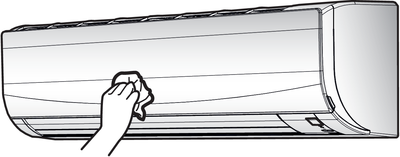
Clean the front panel with a soft cloth. If it is difficult to remove stains, use water or a neutral detergent.
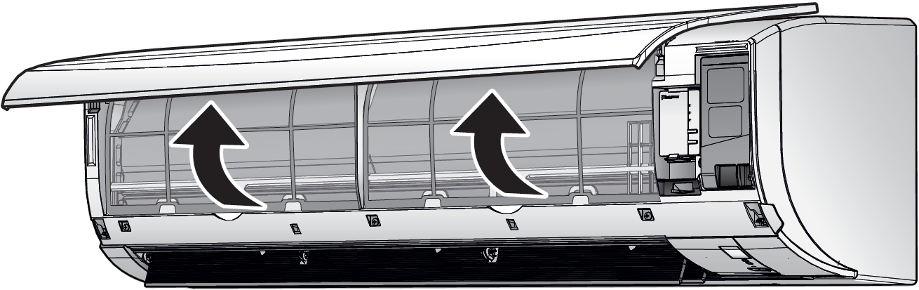
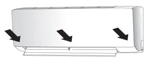
To Open the Front Panel
Hold the front panel by the panel tabs on both sides and open it.
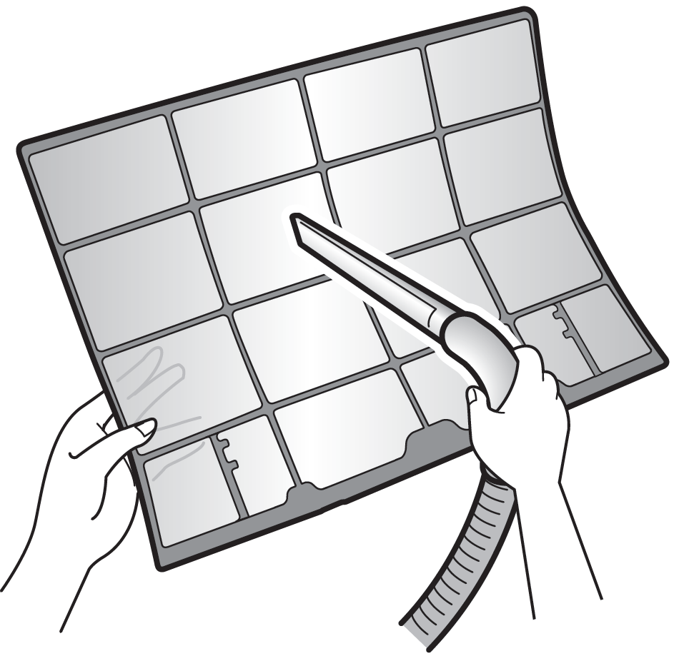
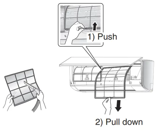
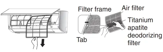
To Clean the Air Filters
- Push the tab at the center of each air filter, then pull it down.
- Pull out the air filters.
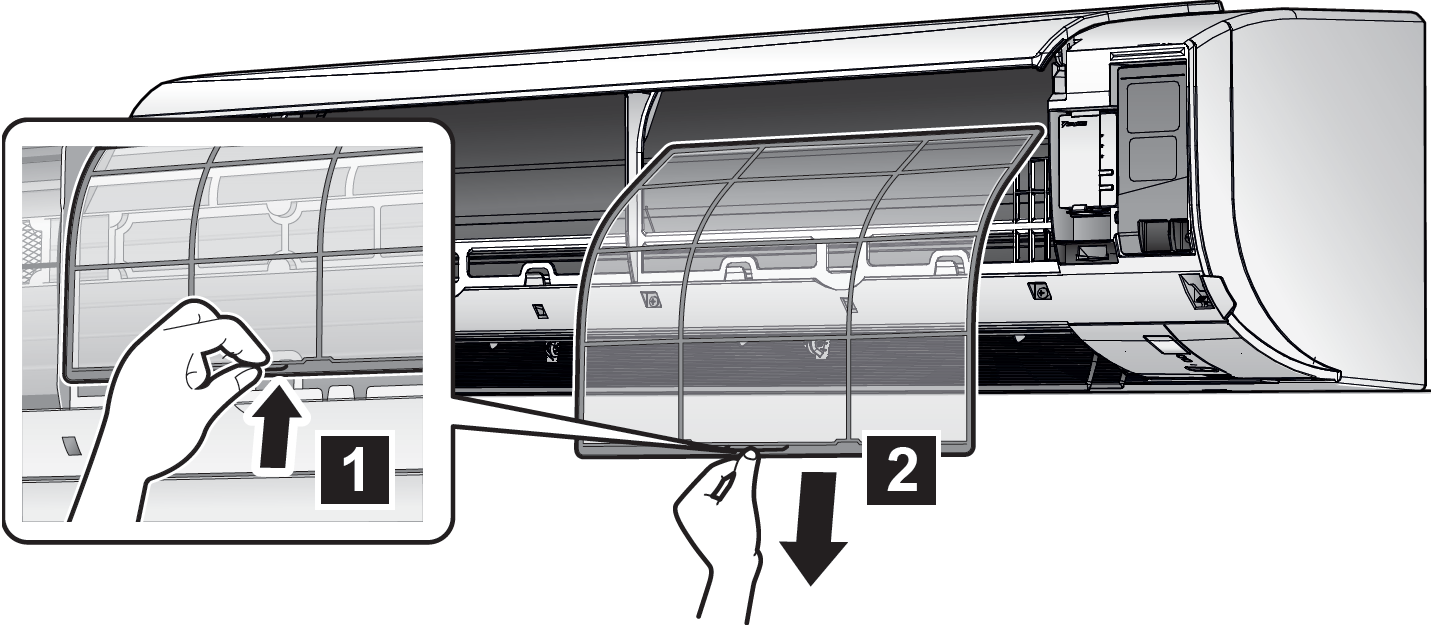
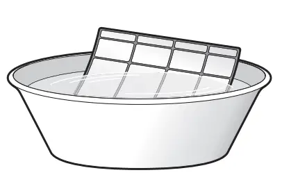
- Wash the air filters with water or clean them with a vacuum cleaner.
- Soak in lukewarm water for about 10 to 15 minutes.
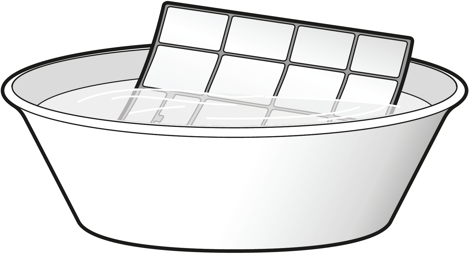
- Install all filters back in their original positions.
INFORMATION
- If the dust does NOT come off easily, wash them with a neutral detergent diluted in lukewarm water. Dry the air filters in the shade.
- It is recommended to clean the air filters every 2 weeks.
To Close the Front Panel
- Set the filters as they were.
- Gently press the front panel at both sides and at the center until it clicks.
To take Following Items into Account Before a Long Idle Period
Operate the unit in fan only mode for several hours to dry the inside of the unit.
- Press MODE and select fan only operation.
- Press ON/OFF to start operation.
- After operation stops, turn the breaker off.
- Clean the air filters and replace them in their original position.
- Remove the batteries from the user interface.
Troubleshooting
If one of the following malfunctions occur, take the measures shown below and contact your dealer.
WARNING
Stop operation and shut OFF the power if anything unusual occurs (burning smells etc.).
Leaving the unit running under such circumstances may cause breakage, electrical shock or fire. Contact your dealer.
The system MUST be repaired by a qualified service person.
| Malfunction | Measure |
| If a safety device such as a fuse, a breaker or an earth leakage breaker frequently actuates or the ON/OFF switch does NOT properly work. | Turn OFF the main power switch. |
| If water leaks from the unit. | Stop the operation. |
| The operation switch does NOT work well. | Turn OFF the power supply. |
| The operation lamp flashes and you can check the error code by the user interface. To display the error code see the user reference guide. | Notify your installer and report the error code. |
If the system does NOT operate properly except for the above mentioned cases and none of the above mentioned malfunctions is evident, investigate the system in accordance with the following procedures.
Disposal
NOTICE
Do NOT try to dismantle the system yourself: dismantling of the system, treatment of the refrigerant, oil and other parts MUST comply with applicable legislation. Units MUST be treated at a specialized treatment facility for reuse, recycling and recovery.
![]()
FTXC20CV1B Room Air Conditioner
User Manual
DAIKIN ROOM AIR CONDITIONER
OPERATION MANUAL
R32 SPLIT SERIES
MODELS
FTXC20CV1B
FTXC25CV1B
FTXC35CV1B
FTXC50CV1B
FTXC60CV1B
FTXC71CV1B
Note:
Illustrations in this manual are for explanation to the user only and may differ from the actual machine. These are subject to change without prior notice for the development of future products.
Safety precautions
![]() Read the precautions in this manual carefully before operating the unit.
Read the precautions in this manual carefully before operating the unit.
 This appliance is filled with R32.
- After reading, keep this manual in a convenient place so that you can refer to it whenever necessary. If the equipment is transferred to a new user, be sure also to hand over the manual.
- Keep this manual where the operator can easily fi nd them.
- Read all safety precautions in this manual carefully before operating the unit.
- For safety reasons, the operator must read the following cautions carefully.
- The precautions described herein are classifi ed as WARNING and CAUTION. They both contain important information regarding safety. Be sure to observe all precautions without fail.
 Never attempt.
![]() Never wet the air conditioner or the remote controller with water.
Never wet the air conditioner or the remote controller with water.
 Be sure to follow the instructions.
![]() Never touch the air conditioner or the remote controller with wet hands.
Never touch the air conditioner or the remote controller with wet hands.
![]() Be sure to establish an earth connection.
Be sure to establish an earth connection.
WARNING
- The appliance must be stored in a room without continuously operating ignition sources (for example open flames, an operating gas appliance or an operating electric heater).
- Do not pierce or burn.
- Be aware that refrigerants may not contain an odor.
- In order to avoid fi re, explosion or injury, do not operate the unit when harmful, among which flammable or corrosive gases, are detected near the unit.
- It is not good for your health to expose your body to the air fl ow for a long time.
- Do not place objects, including rods, your fi gears, etc., in the air inlet or outlet. Product malfunctioning, product or injury damage may result due to contact with the air conditioner’s high-speed fan blades.
- Do not attempt to repair, dismantle reinstall or modify the air conditioner yourself as this may result in water leakage, electric shocks, or fire hazards.
- Do not attempt to install or repair the air conditioner yourself. Improper workmanship may result in water leakage, electric shocks, or fi re hazards. Please contact your local dealer or qualifi ed personnel for installation and maintenance work.
- Do not use the flammable spray near the air conditioner, or otherwise fi re may result.
- Do not place flammable items, such as spray cans, within 1 meter of the air outlet.
- The spray cans may explode as a result of hot air from the indoor or outdoor units.
- When the air conditioner is malfunctioning (giving off a burning odor, etc.) turn off power to the unit and contact your local dealer. Continued operation under such circumstances may result in a failure, electric shocks, or fire hazards.
- Do not use a refrigerant other than the one indicated on the outdoor unit (R32) when installing, moving or repairing. Using another refrigerant may cause trouble or damage to the unit and personal injury.
- The refrigerant used in the air conditioner is safe. Although leaks should not occur, if for some reason any refrigerant happens to leak into the room, make sure it does not come in contact with any flame as of gas heaters, kerosene heaters, or gas range.
- If the air conditioner is not cooling properly, the refrigerant may be leaking, so call your dealer.
- When carrying out repairs accompanying adding refrigerant, check the content of the repairs with our service staff.
- Do not wash the air conditioner with water, as this may result in electric shocks or fire.
- Be sure to install an earth leakage breaker. Failure to install an earth leakage breaker may result in electric shocks or fi re.
- Only connect the air conditioner to the specifi ed power supply circuit. Power suppliers other than the one specifi ed may result in electric shocks, overheating and fires.
- Be sure to earth the unit. Do not earth the unit to a utility pipe, lightning conductor, or telephone earth lead. Imperfect earthing may result in electric shocks.

![]() CAUTION
CAUTION
- Be aware that prolonged, direct exposure to cool or warm air from the air conditioner, or to air that is too cool or too warm can be harmful to your physical condition and health.
- Do not use the air conditioner for purposes other than those for which it is intended. Do not use the air conditioner for cooling precision instruments, food, plants, animals, or works of art as this may adversely affect the performance, quality, and/or longevity of the object concerned.
- Do not expose plants or animals directly to airfl ow from the unit as this may cause adverse effects.
- Do not place appliances that produce naked flames in places exposed to the air fl ow from the unit as this may impair the combustion of the burner.
- Do not block air inlets or outlets. Impaired air fl ow may result in insuffi client performance or trouble.
- Beware of fi re in case of refrigerant leakage. If the air conditioner is not operating correctly, i.e. not generating cool or warm air, refrigerant leakage could be the cause. Consult your dealer for assistance. The refrigerant within the air conditioner is safe and normally does not leak. However, in the event of a leakage, contact with a naked burner, heater, or cooker may result in the generation of noxious gas.
- Do no longer use air conditioner until a qualifi ed service person confirms that the leakage has been repaired.
- Do not sit or place objects on the outdoor unit. Falling yourself or falling objects could cause injury.
- Do not place objects that are susceptible to moisture directly beneath the indoor or outdoor units. Under certain conditions, condensation on the main unit or refrigerant pipes, air filter dirt or drain blockage may cause dripping, resulting in fouling or failure of the object concerned.
- After prolonged use, check the unit stand and its mounts for damage. If left in a damaged condition, the unit may fall and cause injury.
- To avoid injury, do not touch the air inlet or aluminum fi ns of the indoor or outdoor units.
- The appliance is not intended for use by unattended young children or infi rm persons. Impairment of bodily functions and harm to health may result.
- Children should be supervised to ensure that they do not play with the unit or its remote controller. Accidental operation by a child may result in impairment of bodily functions and harm to health.
- Do not sit on the outdoor unit. Put things on the unit, or pull the unit. Doing so may cause accidents, such as falling or toppling down, thus resulting in injury, product malfunctioning, or product damage.
- Do not give impact to the indoor and outdoor units, or otherwise, product damage may result.
- Do not place objects around the indoor unit. Doing so may have an adverse infl uence on the performance, product quality, and life of the air conditioner.
- Be careful not to let pets urinate on the air conditioner. Urination on the air conditioner may result in electric shocks or fire.
- Do not sit or hang on the up and down panel. The up and down panel may fall, and injury or product malfunctioning may result.
- Do not sway the up and down panel. The up and down panel may hit people or objects, and injury or property damage may result.
- Do not let children play around the up and down panel. Injury or property damage may result.
- Do not pull the wires. The wires may be broken and the up and down panel may fall, and injury or property damage may result.
- Do not locate obstacles in the up and down route. The up and down panel may fall, and injury or property damage may result.
- Do not bend or damage the wires. The wires may be broken and the up and down panel may fall, and injury or property damage may result.
- Do not put objects on the up and down panel, or otherwise, production malfunctioning may result.
- Do not use an unstable stand at the time of operating or maintaining the air conditioner, or otherwise, you may topple over or injure yourself.
- Locate the remote controller in places out of reach of children. The wrong operation of the remote controller may result in injury.
- To avoid oxygen depletion, ensure that the room is adequately ventilated if equipment such as a burner is used together with the air conditioner.
- Before cleaning, be sure to stop unit operation, turn the breaker off or remove the power cord.
- Otherwise, an electric shock and injury may result.
- Do not connect the air conditioner to a power supply different from the one as specifi ed. It may cause trouble or fi re.
- Depending on the environment, an earth leakage breaker must be installed. The lack of an earth leakage breaker may result in electric shocks.
- Arrange the drain hose to ensure smooth drainage. Incomplete draining may cause wetting of the building, furniture, etc.
- Do not place objects in direct proximity of the outdoor unit and do not let leaves and other debris accumulate around the unit. Leaves are a hotbed for small animals which can enter the unit. Once in the unit, such animals can cause malfunctions, smoke or fi re when making contact with electrical parts.
- To avoid electric shocks, do not operate with wet hands.

- Do not wash the indoor unit with excessive water, only use a slightly wet cloth.

- Do not place things such as vessels containing water or anything else on top of the unit. Water may penetrate into the unit and degrade electrical insulations, resulting in an electric shock.
Installation site.
To install the air conditioner in the following types of environments, consult the dealer.
- Places with an oily ambient or where steam or soot occurs.
- Salty environment such as coastal areas.
- Places where sulfide gas occurs such as hot springs.
- Places where snow may block the outdoor unit.
- The indoor unit is at least 1m away from any television or radio set (the unit may cause interference with the picture or sound).
- The drain from the outdoor unit must be discharged to a place of good drainage.
Consider nuisance to your neighbors from noises.
Also, pay attention to operating noise.
- Select the following kinds of locations:
A. A place that can suffi ciently withstand the weight of the air conditioner with less running noises and vibrations.
B. A place where warm airfl ow from the air outlet of the outdoor unit and operating noise do not cause a nuisance to neighbors. - Be sure there are no obstructions near the air outlet of the outdoor unit.
- Obstructions may result in poor performance and increased operating noise. If abnormal noise occurs, ask your dealer for advice.
Electrical work.
- For power supply, be sure to use a separate power circuit dedicated to the air conditioner.
System relocation.
- Consult your Daikin dealer about remodeling and relocation.
REMOTE CONTROLLER OVERVIEW
Preparation Before Operation
Accessories
The following accessories are included.
| Drywall screw | Battery | Remote Controller Holder |
 |
 |
 |
| 2 | 2 | 1 |
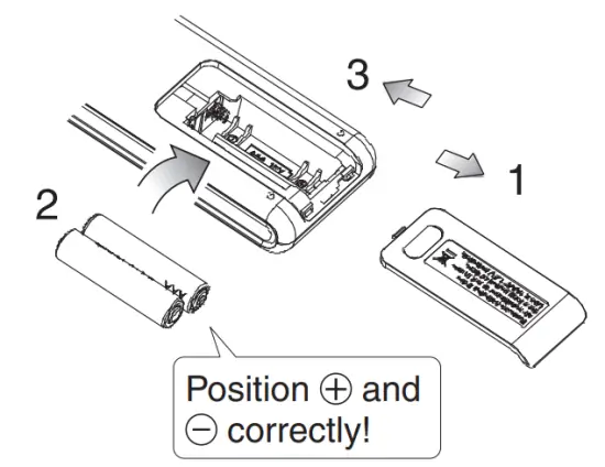
To set the batteries
- Remove the back cover by sliding downwards.
- Insert two dry batteries (LR03:AAA).
- Replace the back cover.
Disposal Requirements
![]() The batteries supplied with the controller are marked with this symbol.
The batteries supplied with the controller are marked with this symbol.
This means that the batteries shall not be mixed with unsorted household waste.
If a chemical symbol is printed beneath the symbol, this chemical symbol means that the battery contains a heavy metal above a certain concentration.
Possible chemical symbols are:
Pb: lead (>0,004%)
Waste batteries must be treated at a specialized treatment facility for re-use. By ensuring correct disposal, you will help to prevent potential negative consequences for the environment and human health. Please contact your local authority for more information.
About batteries
- Remove the batteries from the remote controller if the air conditioner will not be used for an extended period of time.
- When replacing the batteries, it is advised to replace both batteries together with batteries of the same type.
- Batteries should be replaced once a year. However, if the display of the remote controller started to fade or there is a noticeable degradation in performance, replace both batteries with new AAA: LR03 batteries.
- The attached batteries are provided for the initial use of the air conditioner. The usage period of these batteries depends on the manufactured date of the air conditioner.
Preparation Before Operation
To operate the remote controller
- Aim the transmitter of the remote controller at the receiver of the indoor unit.
- Ensure there is no blockage such as a curtain between the indoor unit and the remote controller, signal transmission will be unsuccessful.
To fix the remote controller holder on the wall
- Choose a location where the signal is able to reach the unit.
- Fix the holder onto a wall, a pillar or etc with the screws supplied with the holder.
- Place the remote controller on the holder.
About remote controller
- Do not drop nor wet the remote controller.
- Never expose the remote controller under direct sunlight.
- Dust on the transmitter lens cover will reduce the sensitivity.
- Signal communication may be affected if the air conditioner is being installed near an electronicstarter-type fluorescent lamp (such as an inverter-type lamp) in the room.
To set the clock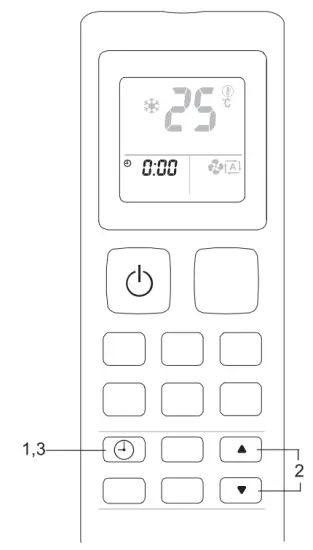 1. Press
 ![]() the button.
the button.
• blinks on the LCD.
2. Press ![]() or
or ![]() set the clock to the present time.
set the clock to the present time.
• Holding down or button rapidly increases or decreases the displayed time.
3. Press ![]() the button.
the button.
- Point the remote controller at the indoor unit when pressing the buttons.
- ” ” blinks.

 stop blinking, the present time will be displayed.
- For example, the present time is 8 o’clock in the morning, will be displayed.
Note
The remote controller is automatically in clock setting mode upon battery insertion. Users are advised to complete the clock setting before operation.
COOL FAN DRY HEAT AUTO Operation
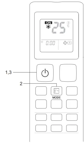
1. Press ![]() the button to start the unit operation.
the button to start the unit operation.
• “is displayed on the LCD.
2. Press![]() the button to choose the desired operation mode.
the button to choose the desired operation mode.
• Each pressing on the button advances the available operating mode in the sequence below:![]()
To stop operation
3. Press ![]() the button again to stop the unit operation.
the button again to stop the unit operation.
Note
| Operating Mode | Description |
| COOL | The air conditioner cools down the room by releasing the heat to the outdoor unit. |
| FAN | The air conditioner indoor unit FAN will run in fan-only. |
| DRY | The air conditioner operates to control the room humidity by regulating the indoor unit fan speed. Therefore, manual adjustment of the fan speed in DRY mode is not available. |
| HEAT | The air conditioner heats up a room to the temperature setpoint. |
| AUTO | The air conditioner cools down or heats up a room to the temperature setpoint. It automatically switches between cooling and heating if necessary. |
Notes on the operating conditions
- The air conditioner will always consume a small amount of electricity even in standby mode.
- Ensure that the power supply/breaker is switched off if the air conditioner is not going to be used for an extended period of time.
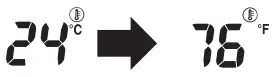
To change the temperature setting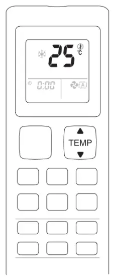 4. Press
 the button.
• Press to raise the temperature and lower the temperature.
| Operating Mode | COOL | HEAT | AUTO | DRY & FAN |
| Set Temperature Range | 18°C -32°C | 10°C -30°C | 18°C -30°C | Not applicable |
- Press
 and
and  simultaneously for 5 seconds to change the temperature display unit to Celcius (°C) or Fahrenheit (°F).
 - For example,
Tips for energy saving
- Keeps the temperature setting at a moderate level (do not over-cool the room).
- Clean the air filters to prevent clogging which could contribute to ineffi client operation and energy wastage.
** Recommended to clean the filter once every 2 weeks for regular users.
To change the fan speed setting
 5. Press
 ![]() the button.
the button.
- Each pressing on the button advances the fan speed mode in sequence.
- In COOL, FAN, HEAT & AUTO mode:
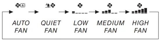 Fan speed setting is not available in DRY mode.
Notes on fan speed setting
• Cooling and heating effect will be affected at lower air fl ow rate
Adjusting the Airfl ow Direction
To change the air flow direction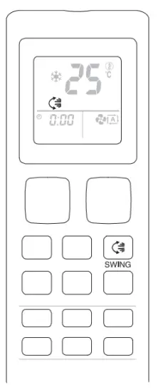 1. Press
 ![]() the button.
the button.
•![]() is displayed on the LCD.
is displayed on the LCD.
To set the flap at the desired position
1. Press![]() the button when the flap reached the desired position.
the button when the flap reached the desired position.
Notes
- Always use the remote controller to adjust the swing angle. Any manual adjustment may break the mechanism of the swing control.
- The cooling and heating effects at different step angles will be affected by different air flow rates.
ECONO Operation
To start the ECONO operation
1. Press ![]() the button.
the button.
•![]() is displayed on the LCD.
is displayed on the LCD.
To cancel the ECONO operation
2. Press![]() the button.
the button.
• ![]() will disappear from the LCD.
will disappear from the LCD.
Notes on ECONO operation
- This function enables effi client operation by limiting the maximum power consumption of the air conditioner unit.
- Pressing
 causes the setting to be canceled and
 disappears from the LCD.
 - If the power consumption level is already low, switching to ECONO operation will not reduce the power consumption.
- ECONO operation will be stopped if the POWERFUL operation is activated.
- ECONO is only available in COOL, DRY, HEAT & AUTO modes.
SLEEP Operation
To start the SLEEP operation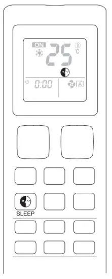
- Press
 the button.
• is displayed on the LCD.
• LED Indication lights of the unit will be dimmed down.
To cancel the SLEEP operation - Press the button.
• will disappear from the LCD.
Notes on SLEEP operation
- Pressing causes the setting to be canceled and disappears from the LCD.
- This operation automatically adjusts the set temperature of the air conditioner to provide a comfortable sleeping environment.
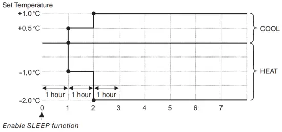
SLEEP is only available in COOL and HEAT mode.
To use OFF TIMER operation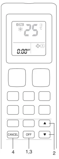 • Ensure the clock setting is set to present time (refer to method to set the clock under preparation before operation).
- Press OFF the button.
•OFF will be displayed on the LCD and blinks. - Press to set the off-timer setting.
• Holding down or button rapidly increases or decreases the time display. - Press OFF the button again.
• OFF stops blinking, and the OFF TIMER set will be displayed.
To cancel OFF TIMER operation - Press the Cancel button to cancel the OFF TIMER.
To use ON TIMER operation
• Ensure the clock setting is set to present time (refer to method to set the clock under preparation before operation).
- Press ON the button.
•ON will be displayed on the LCD and blinks. - Press to set the on-timer setting.
• Holding down or button rapidly increases or decreases the time display. - Press ON the button again
•ON stop blinking, and the ON TIMER set will be displayed.
To cancel ON TIMER operation - Press the Cancel button to cancel the ON TIMER.
Notes on TIMER setting
- When TIMER is set, the present time is not displayed.
- In the following cases, set the timer again.
– After the circuit breaker has turned off.
– After a power failure.
– After replacing the batteries in the remote controller.
To start a POWERFUL operation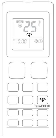
- Press
 the button.
• will be displayed on the LCD.
• POWERFUL operation ends in 20 minutes. The previous setting used before the POWERFUL operation will be resumed.
To cancel the POWERFUL operation - Press the button.
•will disappear from the LCD. The previous setting used before The POWERFUL operation will be resumed.
Notes on POWERFUL operation
- Pressing causes the setting to be canceled and disappears from the LCD.
- In conditions where POWERFUL is started, it will temporarily override the operation of other functions for 20 minutes.
- Indoor unit operating sound will appear to be louder during POWERFUL operation.
- The POWERFUL operation will not increase the capacity of the air conditioner if the air conditioner is already operating in its maximum capacity.
- POWERFUL is available in all operating modes.
Fault Diagnosis
To perform error code diagnosis
- Press and hold CANCEL the button for 5 seconds.
•blinks. - Press CANCEL to check on the error code.
• Keep pressing on the button until a long “beep” acknowledgment is heard from the indoor unit.
To exit from error code diagnosis - Press and hold CANCEL the button for 5 seconds.
Notes
- A short “beep” and two consecutive “beep” acknowledgment from the indoor unit indicates a non-correspondence error code.
- A long “beep” acknowledgment from the indoor unit indicates a correspondence error code.
- The user shall not attempt to repair or modify the air conditioner as any incorrect work may result in electric shock or fi re.
- Consult the service personnel in case the air conditioner is found to be faulty.
Error code definition
| Error Code | Meaning |
| 0 | Normal |
| Al | Malfunction of indoor unit PCB |
| A3 | Drain level control system abnormal |
| A5 | Antifreeze |
| A6 | Indoor fan motor abnormal |
| AH | Electrical air cleaner abnormal |
| C4 | Indoor heat exchanger (1) thermistor short/open |
| C5 | Indoor heat exchanger (2) thermistor short/open |
| C7 | Louver limits switch error |
| C9 | Indoor room thermistor short/open |
| CC | Malfunction of the humidity sensor system |
| CH | |
| El | Outdoor PCB error |
| E3 | High-pressure protection |
| E5 | Compressor motor lock/compressor overload |
| E6 | Compressor start-up error |
| E7 | Outdoor DC fan motor lock |
| E8 | AC input overcurrent |
| EA | 4-way valve error |
| F3 | Discharge pipe overheat |
| F6 | Abnormal high pressure |
| F8 | |
| FA | Heat exchanger overheat |
| HO | Compressor sensor system error |
| H3 | High-pressure switch error |
| H6 | Compressor feedback detection error |
| H7 | Malfunction of outdoor unit fan motor signal |
| H8 | AC current sensor error |
| H9 | Outdoor air thermistor short/open |
| J3 | Compressor discharge pipe thermistor short/open/misplaced |
| J6 | Outdoor heat exchanger thermistor short/open |
| J8 | Liquid pipe thermistor short/open |
| J9 | Gas pipe thermistor short/open |
| L3 | The outdoor control box overheats |
| L4 | Heat sink overheat |
| L5 | IPM error / IGBT error |
| P4 | Heat sink thermistor short/open |
| UO | Insufficient gas |
| U2 | DC voltage out of range |
| U3 | Transmission error |
| U4 | Communication error |
| UA | Installation error |
| OF | Piping & wiring installation mismatch / wrong wiring / insufficient gas |
| UH | Antifreeze (other rooms) |
Note
• After connecting to a wireless LAN adapter, remote controller settings prevail over WLAN apps settings.
Care and Cleaning
CAUTION
- Before cleaning, be sure to stop the operation and turn off the circuit breaker.
- Do not touch the aluminum fins of the indoor unit. If you touch those parts, this may cause an injury.
- Avoid direct contact with any coil treatment cleaners on the plastic parts. This may cause the plastic part to deform as a result of chemical reactions.
Quick reference
Cleaning parts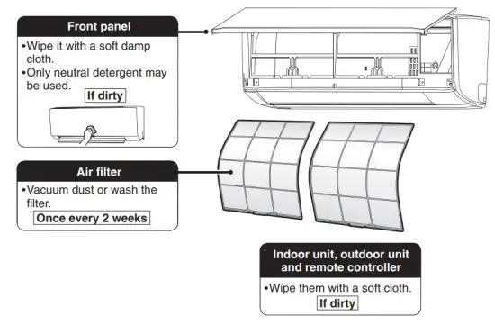
NOTE
For cleaning, do not use any of the following:
- Water hotter than 40°C/104°F
- Volatile liquids such as benzene, gasoline, and thinner
- Polishing compounds
- Rough materials such as a scrubbing brush
Air filter
- Pull out the air filters.
• Open the front panel.
• Push the filter tab at the center of each air filter a little upwards, then pull it down.
- Wash the air filters with water or clean them with a vacuum cleaner.
• It is recommended to clean the air filters every 2 weeks.
If the dust does not come off easily
• Wash the air filters with neutral detergent thinned with lukewarm water, then dry them up in the shade.
• Be sure to remove the titanium apatite deodorizing filter. Refer to “Titanium apatite deodorizing filter”.
- Set the filters as they were and close the front panel slowly.
• Press the front panel on both sides and the center.
* Appearance of the indoor unit may differ from some models.
CAUTION
• Do not touch the aluminum fi ns by bare hand at the time of dismounting or mounting the filter
Titanium apatite deodorizing filter
The titanium apatite deodorizing filter can be renewed by washing it with water once every 6 months. We recommend replacing it once every 3 years.
1. Take off the titanium apatite deodorizing filter
- Open the front panel and pull out the air filter
- Remove titanium apatite deodorizing filter from the back of the air filter.
2. Clean or replace the titanium apatite deodorizing filter.
[Maintenance]
- Vacuum dust, and soak in lukewarm water or water for about 10 to 15 minutes if dirt is heavy.
- After washing, shake off the remaining water and let them dry in the shade.
[Replacement]
- Remove the filter from the back of the air filter.
- Dispose of the old filter as non-flammable waste.
3. Set the filters as they were and close the front panel.
• Press the front panel at both sides and the center.
* Appearance of the indoor unit may differ from some models.
How to open Front Panel
- Open the front panel.
• Hold the panel at the recesses on the main unit (2 recesses on right and left sides) and lift it until it stops. - Remove the front panel.
• While lifting the front panel further, slide it to the left and pull it to the front side. The left rotating shaft is detached. Slide the right rotating shaft to the right and pull it to the front side to remove it.
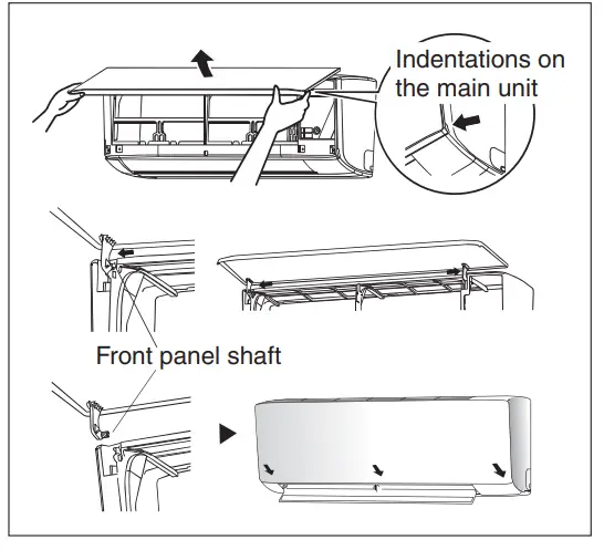
- Attach the front panel.
• Align the right and left rotating shafts of the front panel with the grooves and push them all the way in.
• Gently close the front panel. (Push both ends and the center on the front panel.)
![]() CAUTION
CAUTION
- Don’t touch the metal parts of the indoor unit. It may cause an injury.
- When removing or attaching the front panel, support the panel securely with your hand to prevent it from falling.
- For cleansing, do not use hot water above 40°C, benzine, gasoline, thinner, other volatile oils, polishing compounds, scrubbing brushes, or other hand stuff.
- After cleaning, make sure that the front panel is securely fi xed.
When The Unit Is Not To Be Used For An Extended Long Period Of Time
Operate the unit for 2 hours with the following setting.
Operating mode: cool
Temperature: 30°C/86°F Remove the power plug. If you are using an independent electric circuit for your unit, cut off the circuit. Remove the batteries in the remote control.
TROUBLESHOOTING
For any inquiries on spare parts, please contact your authorized dealer. If any malfunction of the air conditioner unit is noted, immediately switch off the power supply to the unit. Check the following fault conditions and causes for some simple troubleshooting tips.
| Fault | Causes / Action |
| 1. The compressor does not operate 3 minutes after the air conditioner unit Is started. | —Protection against frequent starting. Wait for 3 to 4 minutes for the compressor to start operating. |
| 2. The air conditioner unit does not operate. | — Power failure or the fuse needs to be replaced. —The power plug is disconnected. — It is possible that your delay timer has been set Incorrectly. — If the fault persists after all these verifications, please contact the air conditioner unit Installer. |
| 3. The airflow is too low. | -The air filter is dirty. —The doors or windows are open. —The air suction and discharge are clogged. —The regulated temperature is not high enough |
| 4. Discharge airflow has a bad odor. | —Odors may be caused by cigarettes, smoke particles, perfume, etc. which might have adhered to the coil. |
| 5. Condensation on the front air grille of the indoor unit. | —This is caused by air humidity after an extended long period of operation. —The set temperature is too low, increase the temperature setting and operate the unit at high fan speed. |
| 6. Water flowing out from the air conditioner unit. | —Switch off the unit and call the dealer. |
If the fault persists, please call your local dealer/serviceman.
- In the event that there is any confl it in the interpretation of this manual and any translation of the same in any language, the English version of this manual shall prevail.
- The manufacturer reserves the right to revise any of the specifi cation and designs contained herein at any time without a prior notifi cation.
DAIKIN EUROPE N.V.
Zandvoordestraat 300, B-8400 Oostende, Belgium
DAIKIN MIDDLE EAST AND AFRICA FZE
P.O.Box 18674, Jebel
All Free Zone, Dubai-UAE
Email: [email protected]
Web: www.daikinmea.com
Importer for Turkey DAIKIN ISITMA ye SOdUTMA SISTEMLERI SAN TIC
A.$. Allianz Plaza-Kucukbakkalkoy Ma h.Kayisdagi Cad.
No:1 34750 Atasehir-ISTANBUL /TURKIYE
DAIKIN INDUSTRIES, LTD.
Head office: Umeda Center Bldg., 2-4-12,
Nakazaki-Nishi, Kita-ku, Osaka, 530-8323 Japan
Tokyo office: JR Shinagawa East Bldg., 2-18-1, Konan,
Minato-ku, Tokyo, 108-0075 Japan
http://www.daikin.com/globaV
DAIKIN MALAYSIA SON. EIND.
Lot 60334, Persiaran Bukit Rahman Putra 3,
Taman Perindustrian Bukit Rahman Putra,
47000 Sungai Rulnh Selangor Darul Ehsan, Malaysia.  3P621306-1
![]() DAIKIN ROOM AIR CONDITIONER
DAIKIN ROOM AIR CONDITIONER
Operation Manual
| MODELS | FT13BV1LS |
| FT18BV1LS | |
| FT24BV1LS |

Safety precautions
- Keep this manual where the operator can easily find them.
- Read this manual attentively before starting up the unit.
- For safety reasons, the operator must read the following cautions carefully.
- This manual classifies precautions into WARNINGS and CAUTIONS. Be sure to follow all precautions below: they are all important for ensuring safety.
 WARNING
If you do not follow these instructions exactly, the unit may cause property damage, personal injury, or loss of life.
CAUTION
If you do not follow these instructions exactly, the unit may cause minor or moderate property damage or personal injury.
 Never do.
 Be sure to earth the air conditioner.
 Never touch the air conditioner (including the remote controller) with a wet hand.
 Be sure to follow the instructions.
 Never cause the air conditioner (including the remote controller) to get wet.
WARNING
- In order to avoid fire, explosion or injury, do not operate the unit when harmful, among which flammable or corrosive gases, are detected near the unit.
- It is not good for your health to expose your body to airflow for a long time.
- Do not put a finger, a rod, or other objects into the air outlet or inlet. As the fan is rotating at a high speed, it will cause injury.
- Do not attempt to repair, relocate, modify or reinstall the air conditioner by yourself. Incorrect work will cause electric shocks, fire, etc.
For repairs and reinstallation, consult your Daikin dealer for advice and information. - The refrigerant used in the air conditioner is safe. Although leaks should not occur, if for some reason any refrigerant happens to leak into the room, make sure it does not come in contact with any flame as of gas heaters, kerosene heaters, or gas range.
- If the air conditioner is not cooling properly, the refrigerant may be leaking, so call your dealer.
When carrying out repairs accompanying adding refrigerant, check the content of the repairs with our service staff. - Do not attempt to install the air conditioner by yourself. Incorrect work will result in water leakage, electric shocks, or fire. For installation, consult the dealer or a qualified technician.
- In order to avoid electric shock, fire, or injury, if you detect any abnormality such as the smell of fire, stop the operation and turn off the breaker. And call your dealer for instructions.
- Depending on the environment, an earth leakage breaker must be installed. The lack of an earth leakage breaker may result in electric shocks or fire.
- The air conditioner must be earthed. Incomplete earthing may result in electric shocks. Do not connect the earth line to a gas pipe, water pipe, lightning rod, or telephone earth line.
CAUTION
- In order to avoid any quality deterioration, do not use the unit for cooling precision instruments, food, plants, animals, or works of art.
- Never expose little children, plants, or animals directly to the airflow.
- Do not place appliances that produce open fire in places exposed to the airflow from the unit or under the indoor unit. It may cause incomplete combustion or deformation of the unit due to the heat.
- Do not block air inlets or outlets. Impaired airflow may result in insufficient performance or trouble.
- Do not stand or sit on the outdoor unit. Do not place any object on the unit to avoid injury, do not remove the fan guard.
- Do not place anything under the indoor or outdoor unit that must be kept away from moisture. In certain conditions, moisture in the air may condense and drip.
- After long use, check the unit stand and fittings for damage.
- Do not touch the air inlet and aluminum fins of the outdoor unit. It may cause injury.
- The appliance is not intended for use by young children or infirm persons without supervision.
- Young children should be supervised to ensure that they do not play with the appliance.
- To avoid oxygen deficiency, ventilate the room sufficiently if equipment with a burner is used together with the air conditioner.
- Before cleaning, be sure to stop the operation, turn the breaker off or pull out the supply cord.
- Do not connect the air conditioner to a power supply different from the one specified. It may cause trouble or fire.
- Arrange the drain hose to ensure smooth drainage. Incomplete draining may cause wetting of the building, furniture, etc.
- Do not place objects in direct proximity of the outdoor unit and do not let leaves and other debris accumulate around the unit.
Leaves are a hotbed for small animals which can enter the unit. Once in the unit, such animals can cause malfunctions, smoke, or fire when making contact with electrical
parts. - Do not operate the air conditioner with wet hands.
- Do not wash the indoor unit with excessive water, only use a slightly wet cloth.
- Do not place things such as vessels containing water or anything else on top of the unit. Water may penetrate into the unit and degrade electrical insulations, resulting in an electric shock.
Installation site
To install the air conditioner in the following types of environments, consult the dealer.
- Places with an oily ambient or where steam or soot occurs.
- Salty environment such as coastal areas.
- Places where sulfide gas occurs such as hot springs.
- Places where snow may block the outdoor unit.
The drain from the outdoor unit must be discharged to a place of good drainage.
Consider nuisance to your neighbors from noises
For installation, choose a place as described below.
- A place solid enough to bear the weight of the unit which does not amplify the operation noise or vibration.
- A place from where the air discharged from the outdoor unit or the operation noise will not annoy your neighbors.
Electrical work
- For power supply, be sure to use a separate power circuit dedicated to the air conditioner.
System relocation
- Relocating the air conditioner requires specialized knowledge and skills. Please consult the dealer if the relocation is necessary for moving or remodeling
Names of parts
Indoor Unit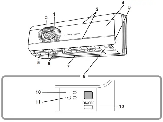
Main unit control panel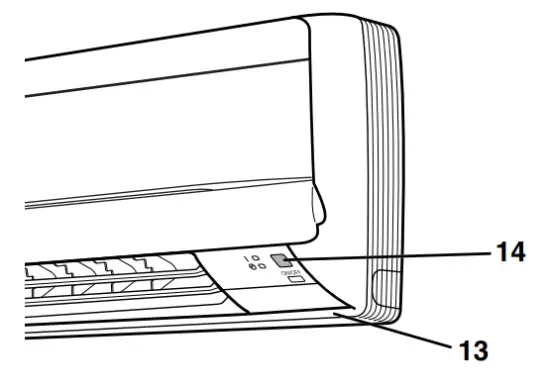
Outdoor Unit
Indoor Unit
- Air filter
- Air purifying filter with photocatalytic deodorizing function:
• These filters are attached to the inside of the air filters. - Air inlet
- Front grille
- Grille tab
- Display
- Air outlet
- Flaps (horizontal blades): (page 12.)
- Louvers (vertical blades):
• The louvers are inside the air outlet. (page 12, 13.) - Operation lamp (green)
- TIMER lamp (yellow): (page 15.)
- Indoor Unit ON/OFF switch:
• Push this switch once to start operation. Push once again to stop it.
• The operation mode refers to the following table.Mode Temperature setting Airflow rate COOL 22°C AUTO • This switch is useful when the remote controller is missing.
- Room temperature sensor:
• It senses the air temperature around the unit. - Signal receiver:
• It receives signals from the remote controller.
• When the unit receives a signal, you will hear a short beep.
• Operation start ………….beep-beep
• Settings changed……….beep
• Operation stop …………..beeeeep
Outdoor Unit - Air inlet: (Back and side)
- Air outlet
- Refrigerant piping and inter-unit cable
- Drain hose
- Earth terminal:
• It is inside of this cover. - Stop valve:
• Dew condensation may form on the stop valve during operation. This does not indicate any type of malfunction in the outdoor unit.
Remote Controller
- Signal transmitter:
• It sends signals to the indoor unit. - Display:
• It displays the current settings.
(In this illustration, each section is shown with all its displays ON for the purpose of explanation.) - POWERFUL button:
for POWERFUL operation (page 14.) - TEMPERATURE adjustment buttons:
• It changes the temperature setting. - ON/OFF button:
• Press this button once to start operation.
Press once again to stop it. - MODE selector button:
• It selects the operation mode. (DRY/COOL/FAN) (page 10.) - FAN setting button:
• It selects the airflow rate setting. - SWING button: (page 12.)
• Flap (Horizontal blade) - SWING button: (page 12.) (18, 24 class only)
• Louver (Vertical blades) - ON TIMER button: (page 16.)
- OFF TIMER button: (page 15.)
- TIMER Setting button:
• It changes the time setting. - TIMER CANCEL button:
• It cancels the timer setting. - CLOCK button: (page 9.)
Preparation Before Operation
To set the batteries
- Press
 with a finger and slide the front cover to take it off.
 - Set two dry batteries (AAA).
- Set the front cover as before.
ATTENTION
About batteries
- When replacing the batteries, use batteries of the same type, and replace the two old batteries together.
- When the system is not used for a long time, take the batteries out.
- We recommend replacing once a year, although if the remote controller display begins to fade or if reception deteriorates, please replace it with new alkali batteries. Using manganese batteries reduces the lifespan.
- The attached batteries are provided for the initial use of the system.
The usable period of the batteries may be short depending on the manufactured date of the air conditioner.
Preparation Before Operation
To operate the remote controller
- To use the remote controller, aim the transmitter at the indoor unit. If there is anything to block signals between the unit and the remote controller, such as a curtain, the unit will not operate.
- Do not drop the remote controller. Do not get it wet.
- The maximum distance for communication is about 7 m.
To fix the remote controller holder on the wall
- Choose a place from where the signals reach the unit.
- Fix the holder to a wall, a pillar, etc.
with the screws supplied with the holder. - Place the remote controller in the remote controller holder.
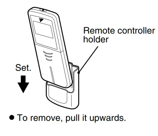
ATTENTION
About remote controller
- Never expose the remote controller to direct sunlight.
- Dust on the signal transmitter or receiver will reduce the sensitivity. Wipe off dust with a soft cloth.
- Signal communication may be disabled if an electronic-starter-type fluorescent lamp (such as inverter-type lamps) is in the room. Consult the shop if that is the case.
- If the remote controller signals happen to operate another appliance, move that appliance to somewhere else, or consult the shop.
To set the clock
- Press the “CLOCK button”.
 is displayed.
 blinks.
 - Press the “TIMER setting button” to set the clock to the present time.
Holding down “ ” or “
 button rap-
idly increases or decreases the time display. - Press the “CLOCK button”.
blinks.
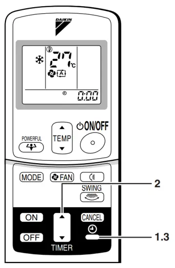
Turn the breaker ON
- Turning ON the breaker opens the flap, then closes it again. (This is a normal procedure.)
NOTE
Tips for saving energy
- Be careful not to cool the room too much.
Keeping the temperature setting at a moderate level helps save energy. - Cover windows with a blind or a curtain.
Blocking sunlight and air from outdoors increases the cooling effect. - Clogged air filters cause inefficient operation and waste energy. Clean them once about every two weeks.
| Recommended temperature setting |
| For cooling:26°C – 28°C |
Please note
- The air conditioner always consumes 15-35 watts of electricity even while it is not operating.
- If you are not going to use the air conditioner for a long period, for example in spring or autumn, turn the breaker OFF.
- Use the air conditioner in the following conditions.
Mode Operating conditions If the operation is continued out of this range COOL Outdoor temperature: 20 to 46 °C
Indoor temperature: 18 to 32 °C
Indoor humidity: 80% max.• A safety device may work to stop the operation. DRY Outdoor temperature: 20 to 46 °C
Indoor temperature: 18 to 32 °C
Indoor humidity: 80% max.• A safety device may work to stop the operation.
• Condensation may occur on the indoor unit and drip. - Operation outside this humidity or temperature range may cause a safety device to disable the system.
DRY · COOL · FAN Operation
The air conditioner operates with the operation mode of your choice.
From the next time on, the air conditioner will operate with the same operation mode.
To start operation
- Press the “MODE selector button” and select an operation mode.
• Each pressing of the button advances the mode setting in sequence.
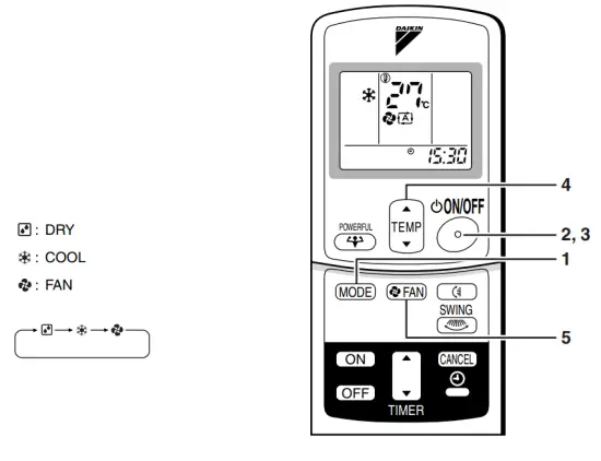
- Press the “ON/OFF button”.
• The OPERATION lamp lights up.
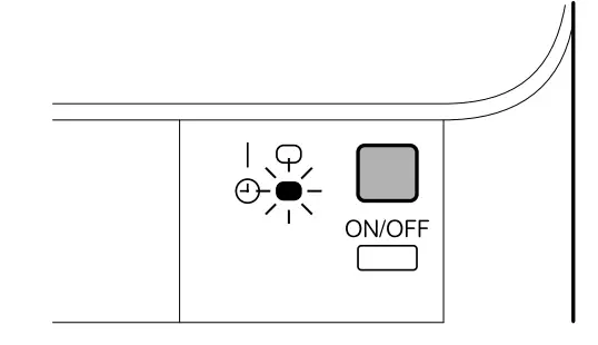 To stop operation
 - Press the “ON/OFF button” again.
• Then the OPERATION lamp goes off.
To change the temperature setting - Press the “TEMPERATURE adjustment button”
DRY or FAN mode COOL mode The temperature setting is not variable. Press “ ” to raise the temperature and press “” to lower the temperature.Set to the temperature you like. 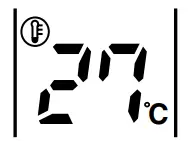
To change the airflow rate setting
- Press the “FAN setting button”.
DRY mode COOL or FAN mode The air flow rate setting is not variable. Five levels of air flow rate setting from 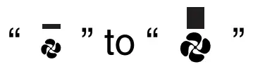 plus “
 ” are available.
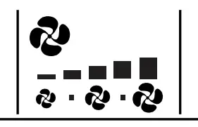
To change the airflow direction
(page 12.)
NOTE
- Note on the DRY operation
• The computer chip works to rid the room of humidity while maintaining the temperature as much as possible. It automatically controls temperature and fan strength, so manual adjustment of these functions is unavailable. - Note on airflow rate setting
• At smaller airflow rates, the cooling effect is also smaller.
Adjusting the Air Flow Direction
You can adjust the airflow direction to increase your comfort.
To adjust the horizontal blades (flaps)
- Press the “SWING button”.
 The display will light up and the flaps will begin to swing.
 - When the flaps have reached the desired position, press the “SWING button” once more.
The display will go blank.
The flaps will stop moving.
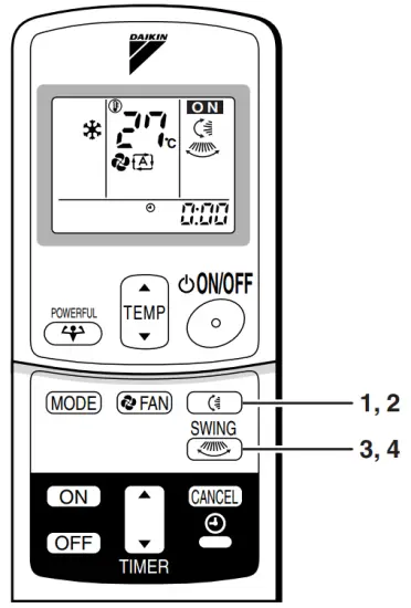 To adjust the vertical blades (louvers) (18, 24 class only)
 - Press the “SWING button”.
 The display will light up and the louvers will begin to swing.
 - When the louvers have reached the desired position, press the “SWING” button once more.
The display will go blank.
The louvers will stop moving.
To 3-D Airflow (18, 24 class only)
1. 3. press the “SWING button”: the “ ” “ ” display will light up and the flaps and louvers will move in turn.
To cancel 3-D Airflow (18, 24 class only)
2. 4. press the “SWING button”
To adjust the vertical blades (louvers) (13 class only)
Hold the knob and move the louvers.
(You will find a knob on the left-side and the right-side blades.)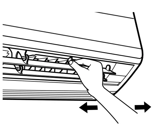 Notes on louvers angles
ATTENTION
- Always use a remote controller to adjust the louver’s angles. Inside the air outlet, a fan is rotating at a high speed. (18, 24 class only)
- Be careful when adjusting the louvers. Inside the air outlet, the fan is rotating at a high speed. (13 class only)
Notes on flap angle
- When the “SWING button” is selected, the flap swinging range depends on the operation mode. (See the figure.)
Three-Dimensional (3-D) Airflow
- Using three-dimensional airflow circulates cold air, which tends to collect at the bottom of the room, and hot air, which tends to collect near the ceiling, throughout the room, preventing areas of cold and hot from developing.
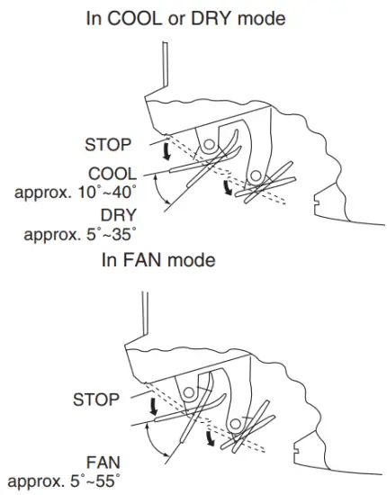
ATTENTION
- Always use a remote controller to adjust the flaps angle.
If you attempt to move it forcibly with your hand when it is swinging, the mechanism may be broken.
POWERFUL Operation
The POWERFUL operation quickly maximizes the cooling (heating) effect in any operation mode. You can get the maximum capacity.
1. Press the “POWERFUL button”.
- POWERFUL operation ends in 20 minutes.
Then the system automatically operates again with the settings which were used before POWERFUL operation. - When using POWERFUL operation, there are some functions that are not available.
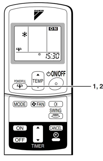 To cancel the POWERFUL operation
2. Press the “POWERFUL button” again.
NOTE
Notes on POWERFUL operation
- In COOL mode
To maximize the cooling effect, the capacity of the outdoor unit must be increased and the air flow rate is fixed to the maximum setting.
The temperature and airflow settings are not variable. - In DRY mode
The temperature setting is lowered by 2.5°C and the airflow rate is slightly increased. - In FAN mode
The airflow rate is fixed to the maximum setting.
TIMER Operation
Timer functions are useful for automatically switching the air conditioner on or off at night or in the morning. You can also use OFF TIMER and ON TIMER in combination.
To use OFF TIMER operation
• Check that the clock is correct.
If not, set the clock to the present time.
(page 9.)
- Press “OFF TIMER button”.
 is displayed.
 blinks.
 - Press the “TIMER Setting button” until the time setting reaches the point you like.
• Every pressing of either button increases or decreases the time setting by 10 minutes. Holding down either button change the setting rapidly.
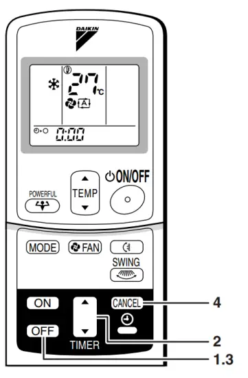
- Press the “OFF TIMER button” again.
• The TIMER lamp lights up.
To cancel the OFF TIMER operation - Press the “CANCEL button”.
• The TIMER lamp goes off.
Notes
- When TIMER is set, the present time is not displayed.
- Once you set ON, OFF TIMER, the time setting is kept in the memory. (The memory is canceled when remote controller batteries are replaced.)
- When operating the unit via the ON/OFF Timer, the actual length of operation may vary from the time entered by the user. (Maximum approx. 10 minutes)
NIGHT SET MODE
When the OFF TIMER is set, the air conditioner automatically adjusts the temperature setting (0.5°C up in COOL) to prevent excessive cooling for your pleasant sleep.
To use ON TIMER operation
• Check that the clock is correct. If not, set the clock to the present time (page 9.).
- Press the “ON TIMER button”.
 is displayed.
 blinks.
 - Press the “TIMER Setting button” until the time setting reaches the point you like.
• Every pressing of either button increases or decreases the time setting by 10 minutes. Holding down either button changes the setting rapidly.
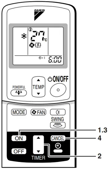
- Press the “ON TIMER button” again.
• The TIMER lamp lights up.
To cancel ON TIMER operation - Press the “CANCEL button”.
• The TIMER lamp goes off.
To combine ON TIMER and OFF TIMER
- A sample setting for combining the two timers is shown below.
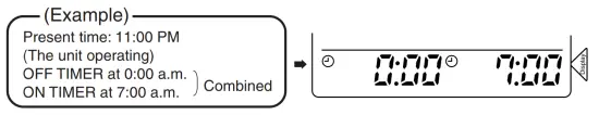
ATTENTION
In the following cases, set the timer again.
- After a breaker has turned OFF.
- After a power failure.
- After replacing batteries in the remote controller.
Care and Cleaning
CAUTION
Before cleaning, be sure to stop the operation and turn the breaker OFF.
Units
Indoor unit, Outdoor unit, and Remote controller
- Wipe them with a dry soft cloth.
Front grille
- Open the front grille.
• Hold the grille by the tabs on the two sides and lift it until it stops with a click.
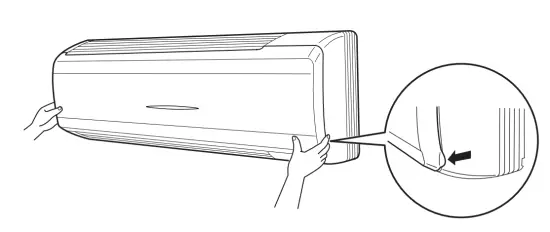
- Remove the front grille.
• Open the front panel further while sliding it to either the left or right and pulling it toward you. This will disconnect the rotation dowel on one side. Then disconnect the rotation dowel on the other side in the same manner.
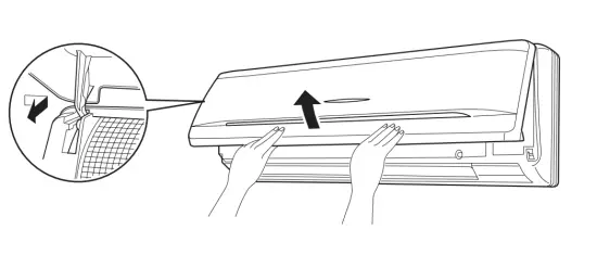
- Clean the front grille
• Wipe it with a soft cloth soaked in water.
• Only neutral detergent may be used.
• In case of washing the grille with water, dry it with a cloth and dry it up in the shade after washing. - Attach the front grille
• Align the rotation dowels on the left and right of the front panel with the slots, then push them all the way in.
• Close the front panel slowly. (Press the panel at both sides and the center.)
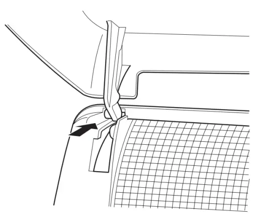
CAUTION
- Don’t touch the metal parts of the indoor unit. If you touch those parts, this may cause an injury.
- When removing or attaching the front grille, use a robust and stable stool and watch your steps carefully.
- When removing or attaching the front grille, support the grille securely with your hand to prevent it from falling.
- For cleaning, do not use hot water above 40 °C, benzine, gasoline, thinner, other volatile oils, polishing compounds, scrubbing brushes, or other hand stuff.
- After cleaning, make sure that the front grille is securely fixed.
Filters
- Open the front grille. (page 17.)
- Pull out the air filters.
• Push a little upwards the tab at the center of each air filter, then pull it down.
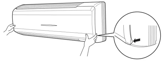
- Take off the air purifying filter with a photocatalytic deodorizing function.
• Press the top of the air-cleaning filter onto the tabs (3 tabs at the top). Then press the bottom of the filter up slightly, and press it onto the tabs (3 at the bottom).
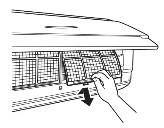
- Clean or replace each filter.
See figure.
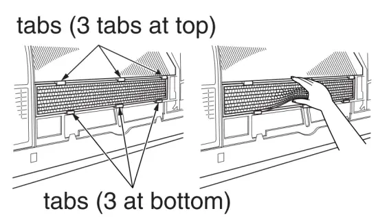
- Set the air filter, air-purifying filter with photocatalytic deodorizing function as they were, and close the front grille.
• Press the front panel on both sides and the center.
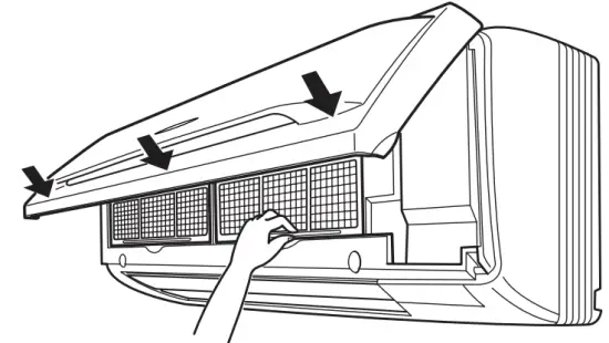
Air Filter
- Wash the air filters with water or clean them with a vacuum cleaner.
• If the dust does not come off easily, wash them with neutral detergent thinned with lukewarm water, then dry them up in the shade.
• It is recommended to clean the air filters every two weeks.
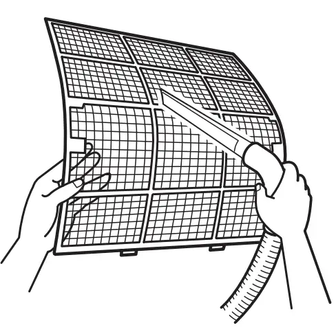
Air purifying filter with photocatalytic deodorizing function. (gray)
The air purifying capacity of the photocatalytic purifying filter can be renewed by washing it with
water once every 6 months. We recommend replacing it once every 3 years.
[ Maintenance ]
- Remove dust with a vacuum cleaner and wash lightly with water.
- If it is very dirty, soak it for 10 to 15 minutes in water mixed with a neutral cleaning agent.
- After washing, shake off the remaining water and dry in the shade
- Since the material is made out of paper, do not wring out the filter when removing water from it.
[ Replacement]
- Remove the tabs on the filter frame and replace them with a new filter.
• Dispose of the old filter as flammable waste.
Check
- Check that the base, stand and other fittings of the outdoor unit are not decayed or corroded.
- Check that nothing blocks the air inlets and the outlets of the indoor unit and the outdoor unit.
- Check that the earth wire is not disconnected or broken.
- Check that the drain comes smoothly out of the drain hose during COOL or DRY operation.
•If no drain water is seen, water may be leaking from the indoor unit. Stop operation and consult the service shop if this is the case.
Before a long idle period
- Operate the “fan-only” for several hours on a fine day to dry out the inside.
• Press the “MODE” button and select the “fan” operation.
• Press the “ON/OFF” button and start operation. - Clean the air filters and set them again.
- Take out batteries from the remote controller.
- Turn OFF the breaker for the room air conditioner.
NOTE
- Operation with dirty filters:
(1) cannot deodorize the air.
(2) cannot clean the air.
(3) results in poor heating or cooling.
(4) may cause odor. - To order an air-purifying filter with a photocatalytic deodorizing function contact the service shop where you bought the air conditioner.
- Dispose of the old air filters as non-burnable and photocatalytic deodorizing filters as burnable waste.
| Item | Part No. |
| Air purifying filter with photocatalytic deodorizing function. (without frame) 1 set | KAF952A42 |
Trouble Shooting
These cases are not trouble.
The following cases are not air conditioner troubles but have some reasons. You may just continue using it.
| Case | Explanation |
The operation does not start soon.
|
|
| The outdoor unit emits water or steam. | In COOL or DRY mode
|
| Mists come out of the indoor unit. | This happens when the air in the room is cooled into mist by the cold airflow during the cooling operation. |
| The indoor unit gives out an odor. | This happens when smells of the room, furniture, or cigarettes are absorbed into the unit and discharged with the airflow. (If this happens, we recommend you to have the indoor unit washed by a technician. Consult the service shop where you bought the air conditioner.) |
| The outdoor fan rotates while the air conditioner is not in operation. | After the operation is stopped:
|
| The operation stopped suddenly. (OPERATION lamp is on) |
For system protection, the air conditioner may stop operating on a sudden large voltage fluctuation. It automatically resumes operation in about 3 minutes. |
Check again.
Please check again before calling a repair person.
| Case | Check |
| The air conditioner does not operate. (OPERATION lamp is off) |
|
| The cooling effect is poor. |
|
| Operation stops suddenly. (OPERATION lamp flashes.) |
Clean the air filters or take all obstacles away and turn the breaker OFF. Then turn it ON again and try operating the air conditioner with the remote controller. If the lamp still flashes, call the service shop where you bought the air conditioner. |
| An abnormal functioning happens during an operation. |
|
Call the service shop immediately.
WARNING
- When an abnormality (such as a burning smell) occurs, stop operation and turn the breaker OFF.
Continued operation in an abnormal condition may result in troubles, electric shocks, or fire.
Consult the service shop where you bought the air conditioner. - Do not attempt to repair or modify the air conditioner by yourself.
Incorrect work may result in electric shocks or fire.
Consult the service shop where you bought the air conditioner.
If one of the following symptoms takes place, call the service shop immediately.
|
Turn the breaker OFF and call the service shop. |
|
|
We recommend periodical maintenance
In certain operating conditions, the inside of the air conditioner may get foul after several seasons of use, resulting in poor performance. It is recommended to have periodical maintenance by a specialist aside from regular cleaning by the user. For specialist maintenance, contact the service shop where you bought the air conditioner.
The maintenance cost must be borne by the user.
Specification
| INDOOR UNIT | FT13BV1LS | FT18BV1LS | FT24BV1LS | ||
| OUTDOOR UNIT | R13BV1LS | R18BV1LS | R24BV1LS | ||
| COOLING CAPACITY | kW | 4.1 | 5.2 | 6.6 | |
| RUNNING CURRENT | A | 5.5 | 7.2 | 11.0 | |
| POWER CONSUMPTION | W | 1180 | 1560 | 2340 | |
| INDOOR UNIT | DIMENSION | H (mm) | 290 | 290 | 290 |
| W (mm) | 1050 | 1050 | 1050 | ||
| D (mm) | 238 | 238 | 238 | ||
| NET WEIGHT | kg | 12 | 12 | 12 | |
| OUTDOOR UNIT | DIMENSION | H (mm) | 540 | 685 | 685 |
| W (mm) | 750 | 800 | 800 | ||
| D (mm) | 270 | 300 | 300 | ||
| NET WEIGHT | kg | 37 | 49 | 61 | |
| Notes: Cooling capacities and electric characteristics are based on 27°C DB, 19°C WB indoor temp, and 35°C DB outdoor temp, at Hi fan speed and 220V, 50Hz. | |||||
![]() SIAM DAIKIN SALES CO.LTD.
SIAM DAIKIN SALES CO.LTD.
22 Soi Onnuch 55/1 On-nuch Rd., Pravet
Subdistrict, Pravet District, Bangkok 10250
Thailand.
Tel : 0-2721-7670-84
Fax : 0-2721-7607-8
 00_CV_3P098595-10R.pdf 2007/3/8/17:54
01_EN_3P098595-10R.pdf 2007/3/17/16:24
02_TH_3P098595-10R.pdf 2007/03/26/17:17
A two-dimensional bar code is a code for manufacturing.
3P098595-10R
M02B111D
(0703)
HT
DAIKIN FT50GAVE Air Conditioner
Safety Precautions
- Read the following warnings and cautions carefully before operating the system and use it correctly.
- This manual classifies the precautions to the user into two categories on the right.
Be sure to follow all as they are all important to ensure safety. - After reading this manual, keep it in a place easily accessible to the user for future reference.
WARNING
Failure to follow a warning is very likely to result in such grave consequences as death or serious injury.
CAUTION
Failure to follow a caution may result in serious injury or property damage, and in certain conditions, may result in a grave consequence.
WARNING
- Do not expose your body to the cool air for a long time, do not cool the room too much.
It will affect your physical conditions and cause health problems. - Do not put a finger, a rod or other objects into the air outlet or inlet.
As the fan is rotating at a high speed, it will cause injury. - Do not attempt to repair, relocate, modify or reinstall the air conditioner by yourself. Incorrect work will cause electric shocks, fire etc. For repairs and reinstallation, consult the shop where you bought the air conditioner.
- If anything abnormal such as a burning smell occurs, stop the operation immediately and turn the breaker OFF.
Continued abnormal operation will cause troubles, electric shocks, fire etc. If anything is abnormal, consult the shop where you bought the air conditioner. - If the air conditioner is not cooling or heating properly, the refrigerant may be leaking, so see the dealer where the unit was purchased. Check with a qualified repairman before attempting any repairs, which might accompany addition of refrigerant.
The refrigerant used in the air conditioner is safe. Although leaks should not occur, if for some reason any refrigerant happens to leak into the room, make sure it does not come in contact with any flame, such as fan heaters, kerosene heaters, or gas ranges, as this may result noxious substances being generated.
CAUTION
- Do not use the air conditioner for preservation purposes.
Do not use it for preserving precision instruments, foods, plants, animals, works of fine arts etc. Performance or quality may deteriorate and animal or plant life may be shorter. - Do not operate the air conditioner with a wet hand.
It may cause an electric shock. - Ventilate the room from time to time.
Be careful especially when using a burning appliance in the same room. Insufficient ventilation may cause shortage of oxygen. - Before cleaning, be sure to stop the operation and turn the breaker OFF.
As a fan is rotating at a high speed, cleaning during operation may cause injury. - After a long use, check the unit stand and fittings for damage.
The unit may drop and cause injury if damage is left unrepaired. - Do not stand or sit on the outdoor unit. Do not place any object on the unit.
The object or the person may fall down or drop, causing injury. - Do not place under the indoor or outdoor unit anything which must be kept away from moisture.
Indoor unit : moisture in the air may condense and drip in certain conditions.
outdoor unit : during cooling operation, condensation may drip from the piping connections. - Do not wash the unit with water.
It may cause an electric shock. - Do not place a burning appliance in places exposed to the air flow from the unit or under the indoor unit.
It may cause incomplete combustion or deformation of the unit from heat. - Do not place a vessel containing water on the unit.
Water may penetrate into the unit and degrade electrical insulations, resulting in an electric shock. - Do not expose plants or animals directly to the air flow.
It may cause adverse effects on the plant or the animal. - Do not block air inlets nor outlets.
Impaired air flow may result in insufficient performance or troubles. - Do not allow children to mount on the outdoor unit or avoid placing any object on it. Falling or tumbling may result in injury.
Installation
WARNING
- Do not attempt to install the air conditioner by yourself.
Consult the service shop or a qualified technician.
Incorrect work will result in water leakage, electric shocks or fire. For installation, consult the service shop where you bought the unit or a qualified technician. - The air conditioner must be earthed.
Incomplete earthing may result in electric shocks. Do not connect the earth line to a gas pipe, water pipe, lightening rod, or a telephone earth line.
CAUTION
- Depending on the environment, an earth leakage breaker must be installed.
Lack of an earth leakage breaker may result in electric shocks. - Do not install the air conditioner in places where flammable gas may leak.
If leaked gas should accumulate near the unit, fire may occur. - Arrange the drain hose to ensure smooth drainage.
Incomplete drainage may cause wetting of the building, furniture etc. - Do not connect the air conditioner to a power supply different from the specification. It may cause trouble or fire.
Installation site
- To install the air conditioner in the following types of environments, consult the shop.
- Places with an oily ambient or where steam or soot occurs.
- Salty environment such as coastal areas.
- Places where sulfide gas occurs such as hot springs.
- Places where snow may block the outdoor unit.
The drain from the outdoor unit must be discharged to a place of good drainage.
Consider nuisance to your neighbours from noises
- For installation, choose a place as described below.
- A place solid enough to bear the weight of the unit which does not amplify the operation noise or vibration.
- A place from where the air discharged from the outdoor unit or the operation noise will not annoy your neighbours.
Electrical work
- For power supply, be sure to use a separate power circuit dedicated to the air conditioner.
System relocation
- Relocating the air conditioner requires specialized knowledge and skills. Please consult the shop where you bought the air conditioner if relocation is necessary for moving or remodeling.
Names of Parts
Indoor unit
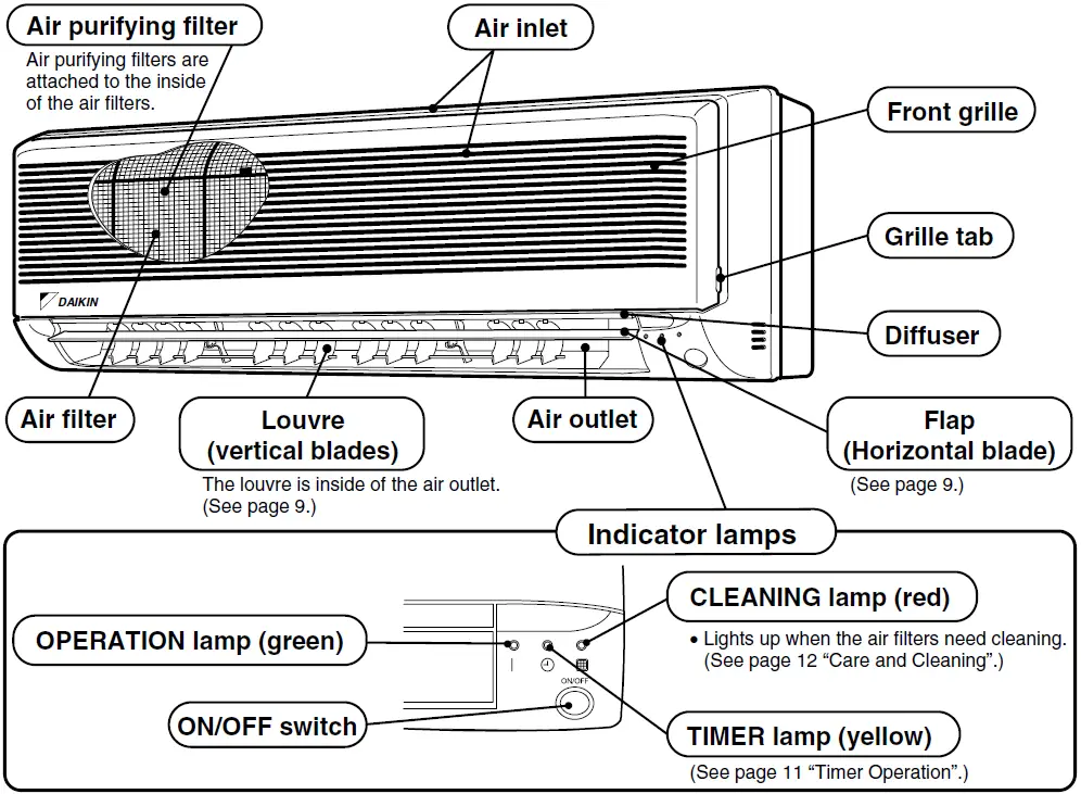
Opening the front grille
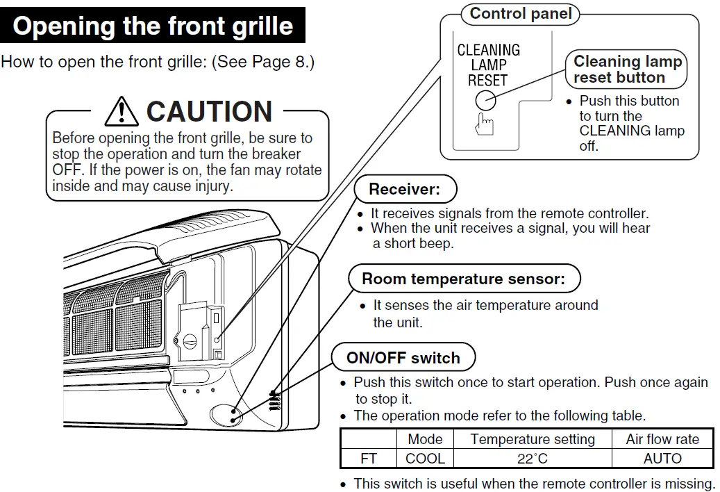
Remote controller
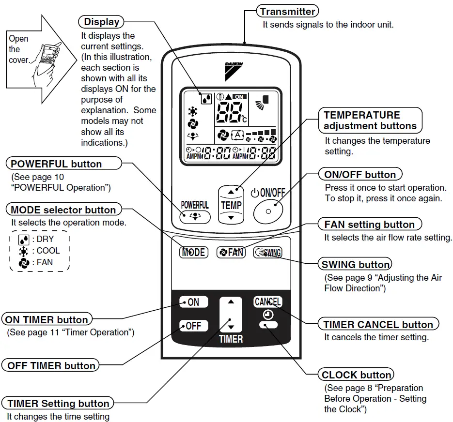
Outdoor unit
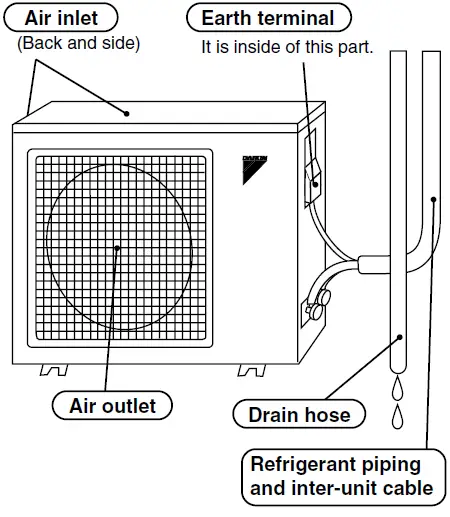
Preparation Before Operation
Remote controller
- Setting the batteries
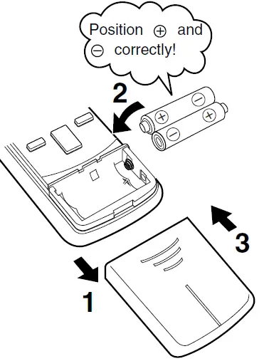
- Press button with a finger and slide the front cover to take it off.
- Set two dry batteries (AAA).
- Set the front cover as before.
- This will cause the figures on the display to flash. Set the clock at this point.
ATTENTION
About batteries
- When replacing the batteries, use batteries of the same type, and replace the two old batteries together.
- When the system is not used for a long time, take the batteries out.
- When the operation display screen of the remote controller is hard to see and the reception become hard, replace the batteries with new AAA batteries.
- The attached batteries are provided for the initial use of the system.
The usable period of the batteries may be short depending on the manufactured date of the air conditioner.
- Operating the remote controller
- To use the remote controller, aim the transmitter at the indoor unit. If there is anything to block signals between the unit and the remote controller, such as a curtain, the unit will not operate.
- Do not drop the remote controller. Do not get it wet.
- The maximum distance for communication is about 7 m.
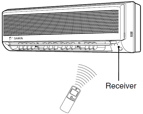
- To fix the remote controller holder on the wall
- Choose a place from where the signals reach the unit.
- Fix the holder to a wall, a pillar, etc. with the screws supplied with the holder.
- Place the remote control in the remote control holder.
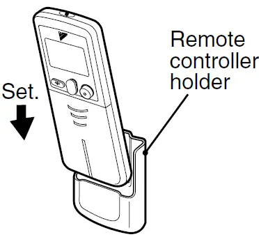
- To remove, pull it upwards
ATTENTION
About the remote controller
- Never expose the remote controller to direct sunlight.
- Dust on the signal transmitter or receiver will reduce the sensitivity. Wipe off dust with soft cloth.
- Signal communication may be disabled if an electronic-starter-type fluorescent lamp (such as inverter-type lamps) is in the room. Consult the shop if that is the case.
- If the remote control signals happen to operate another appliance, move that appliance to somewhere else, or consult the shop.
Indoor unit
- Setting the air purifying filters
- Open the front grille.
- Hold the grille by the tabs on the two sides and lift it until it stops with a click.(about 60°)
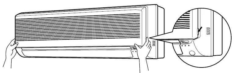
- Hold the grille by the tabs on the two sides and lift it until it stops with a click.(about 60°)
- Pull out the air filters.
- Push upwards the tab at the center of each air filter, then pull it down.
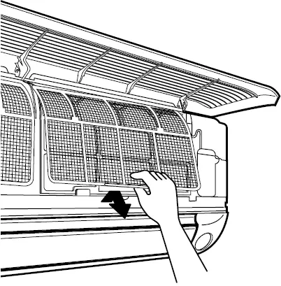
- Push upwards the tab at the center of each air filter, then pull it down.
- Set the air purifying filters.
- Attach an air purifying filter to each air filter. (See page 12 “Care and cleaning”)
- Set the air filters in their original positions and close the front grille.
- Operation without air filters may result in troubles as dust will accumulate inside the indoor unit.
- Open the front grille.
- Setting the clock
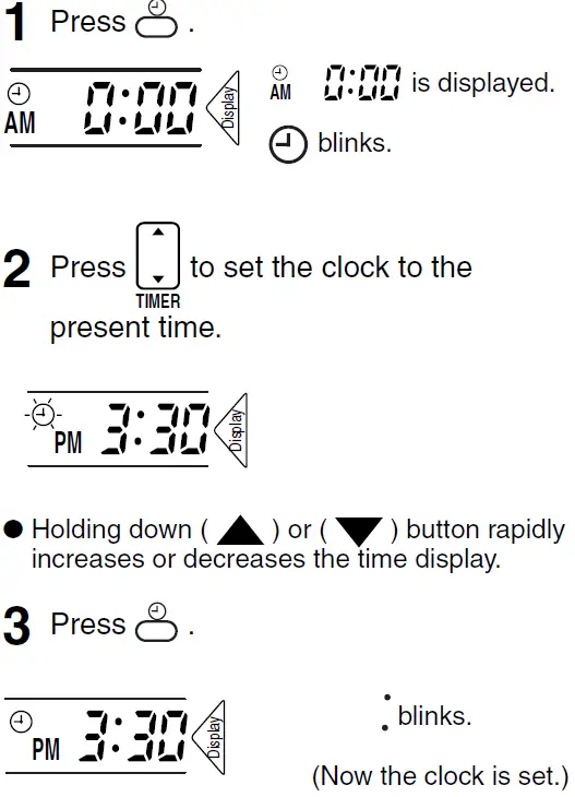
- Turn the breaker ON
- Turning ON the breaker opens the flap, then closes it again. (This is a normal procedure.)
NOTE
Tips for saving energy
- Be careful not to cool the room too much. Keeping the temperature setting at a moderate level helps save energy.
Recommended temperature setting
For cooling: 26°C – 28°C - Cover windows with a blind or a curtain. Blocking sunlight and air from outdoors increases the cooling effect.
- Clogged air filters cause inefficient operation and waste energy. Clean them once in about every two weeks.
Please note
- The air conditioner always consumes 15 – 35 watts of electricity even while it is not operating.
- If you are not going to use the air conditioner for a long period, for example in spring or autumn, turn the breaker OFF.
- Use the air conditioner in the following conditions.
| Mode | Operating conditions | If operation is continued out of this range |
| COOL | Outdoor temperature : 19 to 46 °C Indoor temperature : 18 to 32 °C Indoor humidity : 80% max. |
|
| DRY | Outdoor temperature : 21 to 46 °C Indoor temperature : 18 to 32 °C Indoor humidity : 80% max. |
|
DRY * COOL * FAN Operation
The air conditioner operates with the settings of your choice. From the next time on, the air conditioner will operate with the same settings.
- Press MODE and select a mode.
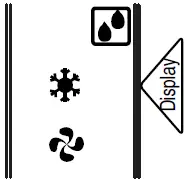
- Each pressing of the button advances the mode setting in sequence.
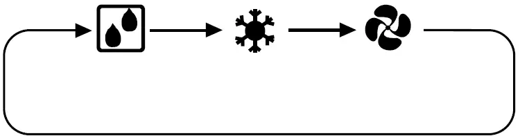
- Each pressing of the button advances the mode setting in sequence.
- Press ON/OFF
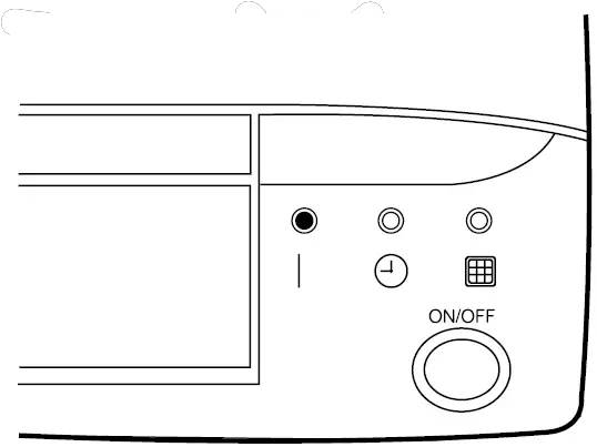 Then OPERATION lamp lights up.
- To stop:
Press ON/OFF once again.
Then OPERATION lamp goes off. - To change the temperature setting:
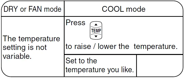
- To change the air flow rate setting: Press FAN.
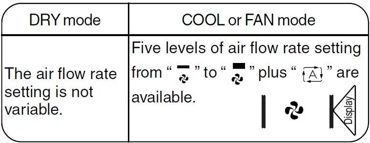
- At smaller air flow rates, cooling or heating effect is also smaller.
Adjusting the Air Flow Direction
You can adjust the air flow direction to increase your comfort.
Adjusting the horizontal blade (flap)
Press Swing.
- Every time the button is pressed, “ appears or disappears.
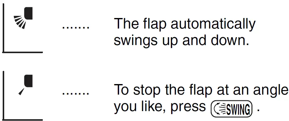
Notes on flap angles
- When SWING is selected, the flap swinging range depends on the operation mode. (See the figure.)
- The real flap angles are differ from the display of remote controller.
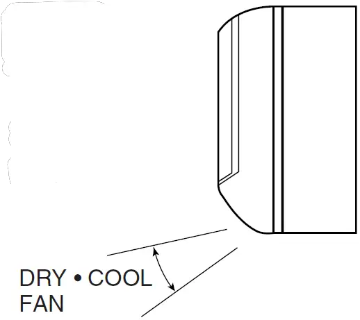
ATTENTION
- Always use a remote controller to adjust the flap angle. If you attempt to move it forcibly with hand when it is swinging, the mechanism may be broken.
Adjusting the vertical blade (louvre)
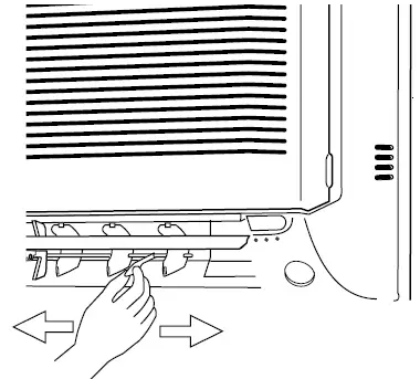
Hold the knob and move the louvre.
(You will find a knob on the left-side and the right-side blades.)
ATTENTION
- Be careful when adjusting the louvre. Inside the air outlet, a fan is rotating at a high speed.
POWERFUL Operation
POWERFUL operation quickly maximizes the cooling effect in any operation mode. You can get the maximum capacity with a touch of a button.
- Pressing the (POWERFUL) button during operation starts POWERFUL operation.
- POWERFUL operation ends in 20 minutes. Then the system automatically operates again with the settings which were used before POWERFUL operation.
- During you use “POWERFUL operation”, the other functions will not go on.
- Press button.
- To cancel POWERFUL operation: Press button.
Notes on POWERFUL operation
- In COOL mode
To maximize the cooling effect, the capacity of outdoor unit must be increased and the air flow rate be fixed to the maximum setting. The temperature and air flow settings are not variable. - In DRY mode
The temperature setting is lowered by 3°C and the air flow rate is slightly increased. - In FAN mode
The air flow rate is fixed to the maximum setting.
Timer Operation
Timer functions are useful for automatically switching the air conditioner on or off at night or in the morning. You can also use OFF TIMER and ON TIMER in combination.
OFF TIMER operation
- Check that the clock is correct.
If not, set the clock to the present time.
- Press OFF while the air conditioner is operating.
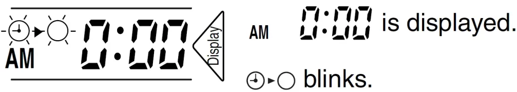
- * Previous time setting appears on display.
- Press UP or DOWN until the time setting reaches the point you like.
- Every pressing of either button increases or decreases the time setting by 10 minutes. Holding down either button changes the setting rapidly.
- Press OFF once again.
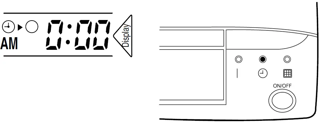 Then the TIMER lamp lights up.
To cancel the timer:
Press CANCEL.
Then the TIMER lamp goes off.
Notes on OFF TIMER
- NIGHT SET MODE
When the OFF TIMER is set, the air conditioner automatically adjusts the temperature setting (0.5°C up in COOL) to prevent excessive cooling for your pleasant sleep.
ON TIMER operation
- Check that the clock is correct. If not, set the clock to the present time.
- Press ON while the air conditioner is not operating.
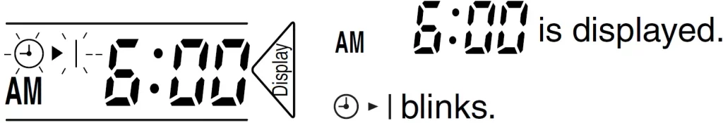 * Previous time setting appears on display.
 - Press Up or DOWN until the time setting reaches the point you like.
- Every pressing of either button increases or decreases the time setting by 10 minutes. Holding down either button changes the setting rapidly.
- Press ON once again.
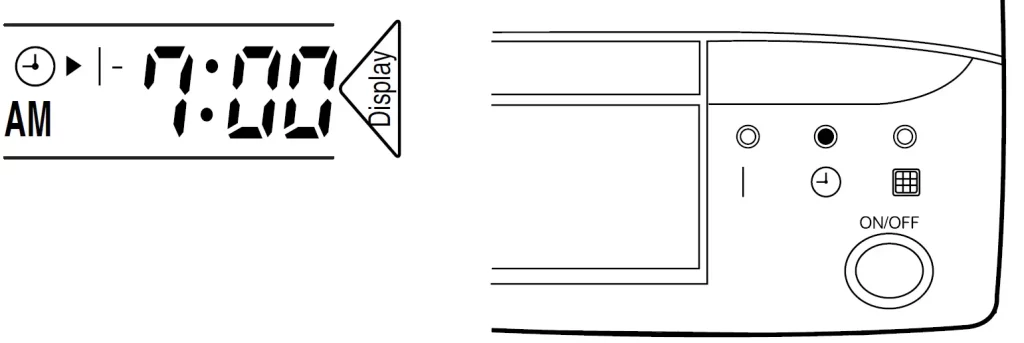
Combining ON TIMER and OFF TIMER
- A sample setting for combining the two timers is shown below.
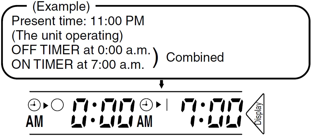
Notes on ON,OFF TIMER
- When TIMER is set, the present time is not displayed.
- Once you set ON,OFF TIMER, the time setting is kept in the memory. (The memory is canceled when remote controller batteries are replaced.)
- When operating the unit via the ON/OFF Timer, the actual length of operation may vary from the time entered by the user.(Maximum approx. 10 minutes.)
ATTENTION
- In the following cases, set the timer again.
- After a breaker has turned OFF.
- After a power failure.
- After replacing batteries in the remote controller.
Care and Cleaning
CAUTION
Before cleaning, be sure to stop the operation and turn the breaker OFF.
Cleaning the air filters
(It is recommended to clean them every two weeks.)
- Clean the air filters, when cleaning lamp lights up.
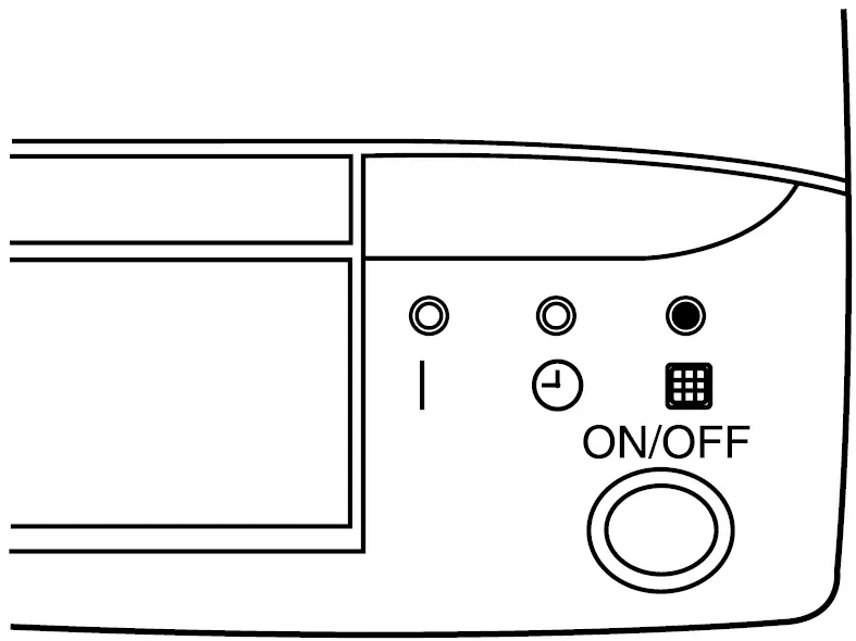
- Open the front grille.
- Hold the grille by the tabs on the two sides and lift it until it stops with a click. (about 60°)
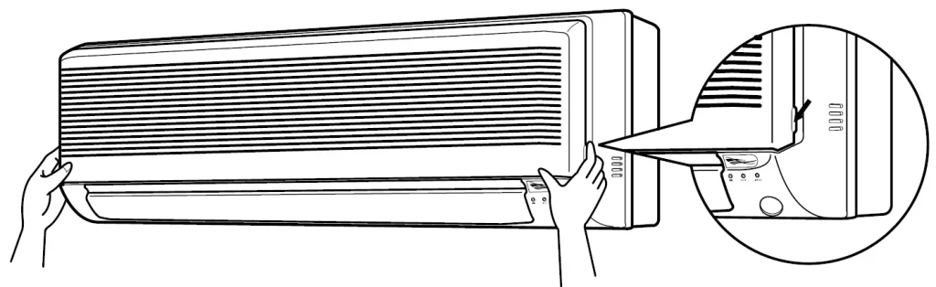
- Hold the grille by the tabs on the two sides and lift it until it stops with a click. (about 60°)
- Push cleaning lamp reset button.
- Pull out the air filters.
- Push a little upwards the tab at the center of each air filter, the pull it down.
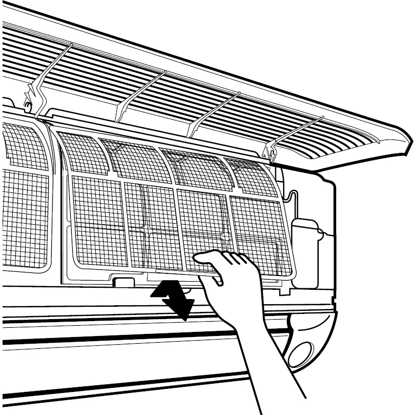
- Push a little upwards the tab at the center of each air filter, the pull it down.
- Take off the air purifying filters and clean them.
- Wash them with water, or clean them with a vacuum cleaner.
- If the dust does not come off easily, wash them with neutral detergent thinned with lukewarm water, then dry them up in the shade.
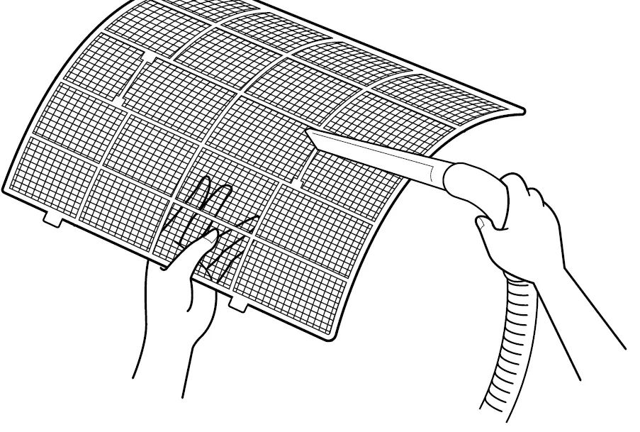
- Set the air purifying filters and the air filters as they were and close the front grille.
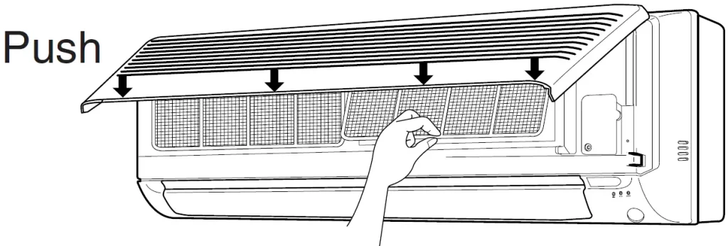
- Insert claws of the filters into slots of the front panel. The front grille should lock at both sides and at the point in the middle. Push the grille at the 4 points indicated by Down Arrow.
NOTE
- In a dusty environment, clean the air filters at least once in every two weeks.
- Operation with dusty air filters lowers the cooling capacity and wastes energy.
Cleaning the indoor and outdoor units and the remote controller
- Wipe them with dry soft cloth.
For cleaning, do not use water hotter than 40°C, benzine, gasoline, thinner, nor other volatile oils, polishing compound, scrubbing brushes nor other hard stuff.
Replacing air purifying filters
(It is recommended to replace them every three months.)
- Air purifying filters need to be replaced regularly.
- Open the front grille and pull out the air filters.
- Take off the air
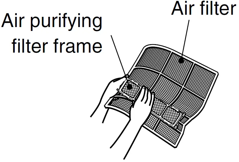
- Hold the recessed parts of the frame and unhook the four claws.
- Detach the filter
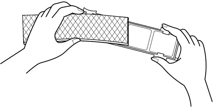
- Attach the air purifying filter.
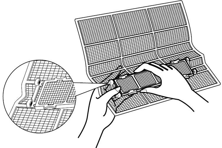
- Set the air filters as they were and close the front grille.
(Push the grille at the 4 points, two at both sides and in the middle.)
NOTE
- To order air purifying filters, contact the service shop where you bought the air conditioner.
- Once the air purifying filter element gets dirty, it is not reusable but must be thrown away.
- Operation with dirty air purifying filters:
- cannot clean the air.
- results in poor cooling.
- may cause odour.
| Item | Part No. |
| Air purifying filter (with frame) | KAF918A41 |
| Air purifying filter (without frame) | KAF918A42 |
Cleaning the front grille
You may remove the front grille for cleaning.
CAUTION
- When removing or attaching the front grille, use a robust and stable stool and watch your steps carefully.
- When removing or attaching the front grille, support the grille securely with hand to prevent it from falling.
- For cleaning, do not use water hotter than 40°C, benzine, gasoline, thinner, nor other volatile oils, polishing compound, scrubbing brushes nor other hard stuff.
- After cleaning, make sure that the front grille is securely fixed.
- Open the front grille.
- Hold the grille by the tabs on the two sides and lift it until it stops with a click.
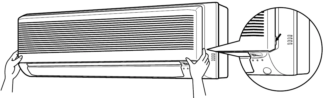
- Hold the grille by the tabs on the two sides and lift it until it stops with a click.
- Remove the front grille.
- Supporting the front grille with one hand, release the lock by sliding down the knob with the other hand.
- To remove the front grille, pull it toward yourself with both hands.
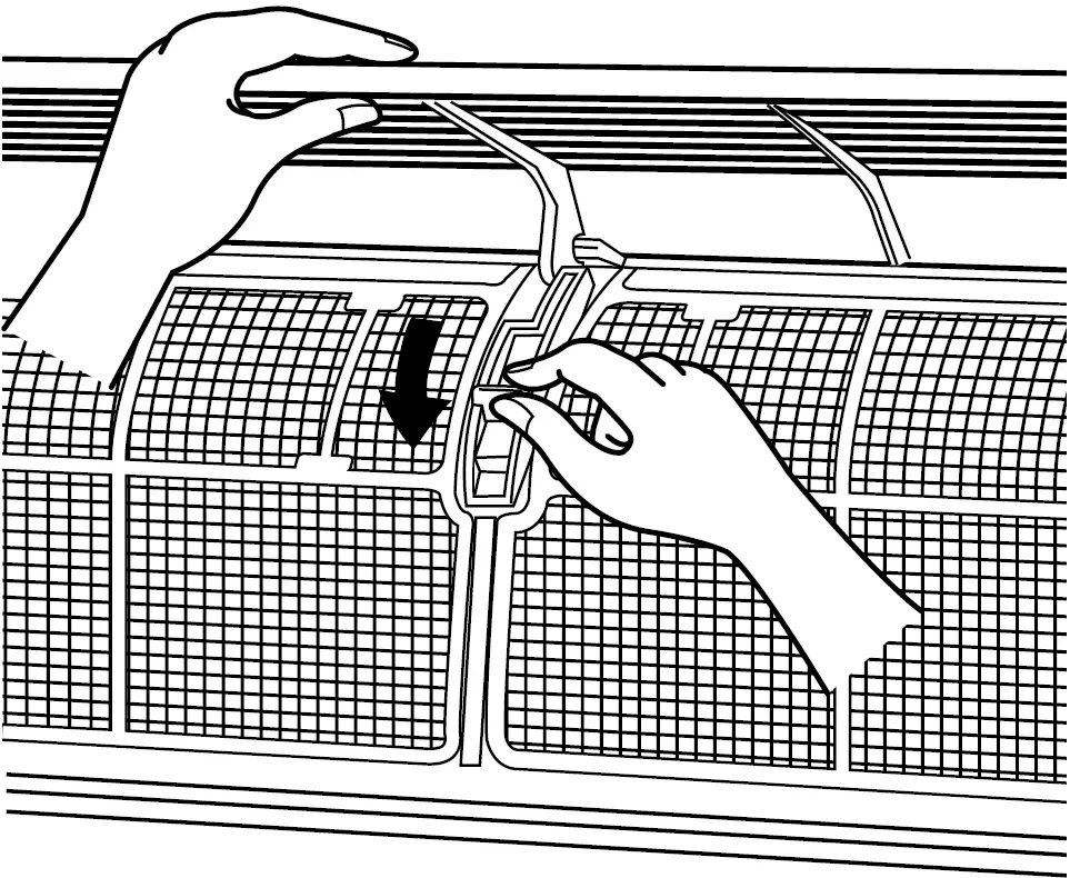
- Clean the front grille.
- You may wipe it with a soft cloth soaked in water.
- Only neutral detergent may be used.
- You may wash the grille with water. After washing, dry it with cloth, then dry it up in the shade.
- Attach the front grille.
- Set the 3 keys of the front grille into the slots and push them in all the way.
- Supporting the front grille with one hand, fit the lock by sliding up the knob with the other hand.
- Close the front grille slowly in this state.(Push the grille at the 3 points, two at both sides and in the middle.)
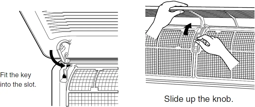
Check
Check that the base, stand and other fittings of the outdoor unit are not decayed or corroded.
Check that nothing blocks the air inlets and the outlets of the indoor unit and the outdoor unit.
Check that the drain comes smoothly out of the drain hose during COOL or DRY operation.
- If no drain water is seen, water may be leaking from the indoor unit. Stop operation and consult the service shop if this is the case.
Before a long idle period
- Operate the fan alone for several hours on a fine day to dry out the inside.
- Press MODE and select “Mode”.
- Press ON/OFF.
- After operation stops, turn off the breaker for the room air conditioner.
- Clean the air filters and set them again.
- Take out batteries from the remote controller.
Trouble Shooting
- These cases are not troubles.
The following cases are not air conditioner troubles but have some reasons. You may just continue using it.
| Case | Explanation |
| Operation does not start soon.
● When ON/OFF button was pressed soon after operation was stopped. ● When the mode was reselected. |
● This is to protect the air conditioner. You should wait for about 3 minutes. |
| The outdoor unit emits water or steam. | ■ In COOL or DRY mode
· Moisture in the air condenses into water on the cool surface of outdoor unit piping and drips. |
| Mists come out of the indoor unit. | ■ This happens when the air in the room is cooled into mist by the cold air flow during cooling operation. |
| The indoor unit gives out odour. | ■ This happens when smells of the room, furniture, or cigarettes are absorbed into the unit and discharged with the air flow.
(If this happens, we recommend you to have the indoor unit washed by a technician. Consult the service shop where you bought the air conditioner.) |
| The outdoor fan rotates while the air conditioner is not in operation. | ■ After operation is stopped:
· The outdoor fan continues rotating for another 60 seconds for system protection. ■ While the air conditioner is not in operation: · When the outdoor temperature is very high, the out door fan starts rotating for system protection. |
| The operation stopped suddenly.
(OPERATION lamp is on) |
■ For system protection, the air conditioner may stop operating on a sudden large voltage fluctuation.
It automatically resumes operation in about 3 minutes. |
- Check again
Please check again before calling a repair person.
| Case | Check |
| The air conditioner does not operate.
(OPERATION lamp is off) |
● Hasn’t a breaker turned OFF or a fuse blown?
● Isn’t it a power failure? ● Are batteries set in the remote controller? ● Is the timer setting correct? |
| Cooling effect is poor. | ● Are the air filters clean?
● Is there anything to block the air inlet or the outlet of the indoor and the outdoor units? ● Is the temperature setting appropriate? ● Are the windows and doors closed? ● Are the air flow rate and the air direction set appropriately? |
| Operation stops suddenly. (OPERATION lamp blinks.) | ● Are the air filters clean?
● Is there anything to block the air inlet or the outlet of the indoor and the outdoor units? Clean the air filters or take all obstacles away and turn the breaker OFF. Then turn it ON again and try operating the air conditioner with the remote controller. If the lamp still blinks, call the service shop where you bought the air conditioner. |
| An abnormal functioning happens during operation. | ● The air conditioner may malfunction with lightening or radio waves. Turn the breaker OFF, turn it ON again and try operating the air conditioner with the remote controller. |
- Call the service shop immediately.
WARNING
- When an abnormality (such as a burning smell) occurs, stop operation and turn the breaker OFF.
Continued operation in an abnormal condition may result in troubles, electric shocks or fire.
Consult the service shop where you bought the air conditioner. - Do not attempt to repair or modify the air conditioner by yourself.
Incorrect work may result in electric shocks or fire.
Consult the service shop where you bought the air conditioner.
If one of the following symptoms takes place, call the service shop immediately.
- The power cord is abnormally hot or damaged.
- An abnormal sound is heard during operation.
- The safety breaker, a fuse, or the earth leakage breaker cuts off the operation frequently.
- A switch or a button often fails to work properly.
- There is a burning smell.
- Water leaks from the indoor unit.
Turn the breaker OFF and call the service shop.
- After a power failure
The air conditioner automatically resumes operation in about three minutes. You should just wait for a while. - Lightning
If lightning may strike the neighboring area, stop operation and turn the breaker OFF for system protection.
We recommend periodical maintenance
In certain operating conditions, the inside of the air conditioner may get foul after several seasons of use, resulting in poor performance. It is recommended to have periodical maintenance by a specialist aside from regular cleaning by the user. For specialist maintenance, contact the service shop where you bought the air conditioner.
The maintenance cost must be born by the user.
![]()
Operation manual
Room thermostat
About this document
Thank you for purchasing this product. Please:
▪ Keep the documentation for future reference.
Target audience
End users
Documentation set
This document is part of a documentation set. The complete set consists of:
- Installation manual:
- Installation instructions
- Format: Paper (supplied in the kit)
- Operation manual:
- Installation instructions
- Format: Paper (supplied in the kit)
The latest revisions of the supplied documentation may be available on the regional Daikin website or via your installer.
The original documentation is written in English. All other languages are translations.
Room thermostat: Overview
The EKRTRB room thermostat is a programmable, wireless digital thermostat, designed to control your Daikin system, where comfort, simplicity and energy-saving go hand in hand. It is mainly used for existing installations.
An optional external temperature sensor (EKRTETS) can be connected to EKRTRB to be used as either a floor temperature sensor or as an external ambient temperature sensor.
2.1 Buttons
Overview
a Decrease button
b Increase button
c OK button
d Left and right navigation buttons
e Back button
f Edit button
g Button cover
Navigation —![]()
- Select an operation mode.
- In program mode, cycle between the days of a program.
- In the parameter menu, select a parameter to modify.
OK —![]()
- Confirm a selection.
- Confirm and save modifications to parameters, programs or date and time (blinking green LED).
- Short press to light up the thermostat backlight when it has become unlit.
- In OFF mode, press to display the current temperature and time.
- Override the open window function (if enabled). The button contains an LED that may display additional information about the system:
| LED state | Meaning |
| Red, fixed | Heating demand |
| Green, fixed | Cooling demand |
| Red, blinking | Sensor or battery error |
| Green, blinking | Confirm and save modifications |
Decrease/Increase — +-
- Adjust the temperature setpoint.
- Adjust values in any of the deeper menus, the user menu or the installer menu.
Back —
- Go back to a previous value or cancel an action.
- Press simultaneously to activate the button lock function.
- On the main screen, press to quickly cycle between which value is visualized: current temperature setpoint, ambient temperature, the temperature measured by the external temperature sensor, or humidity percentage. (1)
- Press and hold for 5 seconds to enter the installer menu.
Edit —
- In normal operation modes, press and hold for 2 seconds to modify the date and time.
- In program mode, press to edit a user program.
- Press and hold for 5 seconds to enter the parameter menu.
- Press in combination with to enable or disable button lock functionality.
2.2 Status icons![]()
a Reversible mode
b Timer mode
c Holiday mode
d Comfort mode
e Automatic mode
f Reduced mode
g OFF mode
h Program mode
i Program or parameter number
j Heating demand
k Cooling demand
l Parameter indicator
m Dew prevention
n Wireless communication with the receiver
o Sensor
p Low battery indicator
q Temperature unit
r Button lock
s Program step (current and in program creation)
t Manual override
u Day of the week
v Current day program
w Time or parameter name
x Temperature, humidity or parameter value
Operation
3.1 Date and time
After inserting the batteries, the room thermostat display will power on and will prompt you to set the current date and time. This is required before you can actually use the room thermostat.
3.1.1 To set date and time
- Adjust the currently selected value with
 The value that is currently being modified flashes.
 - Press
 to confirm a value. Result: The room thermostat jumps to the next value automatically.
 - Set the other values as desired.
- After setting the last value, the room thermostat will ask you to confirm and save your changes. Press (LED blinking green) to save the date and time settings.
Result: The room thermostat date and time are set and the room thermostat shows the main screen.
Values are set in the following order:
- Hour
- Minutes
- Days of the week (1~7 = Monday~Sunday)
- Day number (e.g. 15 April)
- Month number (1~12)
- Year
![]() INFORMATION
INFORMATION
You can access the date and time settings while in any of the normal operating modes at any time by pressing and holding for 2 seconds.
3.2 Operation modes
The room thermostat can be set to operate in several different modes to allow you to adjust your system according to your needs and preferences.
| Icon | Mode | Description |
| Comfort mode | Used for a fixed temperature on comfort level .0′ | |
| Reduced modem | Used for a fixed temperature on a reduced level .`1 | |
| AUTO | Automatic mode | The room thermostat automatically follows the steps defined in the selected program (built-in or user-defined). |
| OFF mode | Switches off your unit. | |
| Holiday mode | Used to set a fixed temperature during a long period of absence. | |
| Timer mode | Used to set a fixed temperature for only a specific period of time | |
| Reversible mode | Used to set the unit operation mode to heating or cooling (only applicable for reversible units). | |
| Program mode | Used to select the program for the room thermostat programs and to create or modify user-defined programs. |
(a) The default temperature setpoint in this mode is 21°C for heating and 24°C for cooling.
(b) If the unit operation mode is cooling, reduced mode acts as OFF mode.
(c) The default temperature setpoint in this mode is 17°C for heating.
3.2.1 To change the operation mode
Prerequisite: You are on the main screen.
- Use
 to move the cursor to the desired mode.
 - Press to activate the selected operation mode.
INFORMATION
![]() Reversible mode is ONLY applicable to installations with reversible units. The reversible mode menu is ONLY available if parameter 21 (MOde) is set to “rEv”. See”To
Reversible mode is ONLY applicable to installations with reversible units. The reversible mode menu is ONLY available if parameter 21 (MOde) is set to “rEv”. See”To
enable reversible mode” [6] for more information.
3.2.2 To change the temperature setpoint
Prerequisite: The room thermostat is in comfort mode ( ![]() ) or reduced mode (
) or reduced mode ( ![]() ).
).
- Press .
Result: The temperature on the room thermostat display blinks. - Use
 set the desired setpoint.
Result: The temperature changes to the desired setpoint.
3.2.3 Automatic mode
AUTO
In automatic mode, the room thermostat automatically follows the steps defined in the selected program. In this mode, the following information about the currently selected program is always visible on the screen.
a Day of the week
b Current step in the program
c Current day program (current time bar blinks)
d Currently selected program
Depending on the type of step, the room thermostat will maintain either the comfort (![]() ) or reduced mode (
) or reduced mode (![]() ) temperature setpoint for the duration of that step. You can use one of the built-in programs or create a custom program to be followed by the room thermostat. In order to change, modify or create programs, use program mode.
) temperature setpoint for the duration of that step. You can use one of the built-in programs or create a custom program to be followed by the room thermostat. In order to change, modify or create programs, use program mode.
For more information, see “3.2.5 Program mode” [4 4].
To temporarily override a program
Prerequisite: The room thermostat is in automatic mode.
- Press
. Result: The room thermostat jumps to timer mode automatically. - Select the duration with press to confirm.
- Adjust the desired setpoint with .
- Press to start the function.
Result: The room thermostat displays the remaining duration of the timer and ![]() blinks while the timer is active.
blinks while the timer is active.
To stop the timer function before the end of the duration, press ![]() set the duration to no or use
set the duration to no or use ![]() to switch to a different operation mode.
to switch to a different operation mode.
3.2.4 OFF mode
![]() OFF mode allows you to switch off your unit. In OFF mode, integrated frost protection (fixed, 4°C) remains activated.
OFF mode allows you to switch off your unit. In OFF mode, integrated frost protection (fixed, 4°C) remains activated.
![]() INFORMATION
INFORMATION
In OFF mode, you can still press ![]() on the room thermostat to display the current time and temperature for a few seconds.
on the room thermostat to display the current time and temperature for a few seconds.
To restart your unit again, use ![]() to move the cursor to a different operation mode (e.g. automatic) and press
to move the cursor to a different operation mode (e.g. automatic) and press ![]() to activate it.
to activate it.
3.2.5 Program mode
![]() Program mode is used to select which program you want the room thermostat to follow when in automatic mode. Additionally, program mode is also used for the creation of custom user-defined programs. See “User-defined programs” [5] for more information.
Program mode is used to select which program you want the room thermostat to follow when in automatic mode. Additionally, program mode is also used for the creation of custom user-defined programs. See “User-defined programs” [5] for more information.
Default programs
The room thermostat comes equipped with 9 default programs (P1~P9) for standard situations. If none of the programs matches your needs, you can create a custom program. See “User-defined programs” [5] for more information. For the built-in programs, see the graphical 24-hour representations below.
![]() Depending on the type of step, the room thermostat follows either the reduced mode temperature setpoint (hollow segment) or the comfort mode temperature setpoint (filled in the segment
Depending on the type of step, the room thermostat follows either the reduced mode temperature setpoint (hollow segment) or the comfort mode temperature setpoint (filled in the segment
To change the active program
Prerequisite: The room thermostat is in program mode.
- Use and cycle between the programs and select the desired program. You can choose between P1~P9 (built-in programs) or U1~U4 (user-defined programs).
- Press and view the other days of each program.
- Press.
Result: The program is selected and now active while in automatic mode.
INFORMATION
![]() If you select a user-defined program, you are able to modify the program after pressing
If you select a user-defined program, you are able to modify the program after pressing![]() . For more information, see “To create or modify a user-defined program” [5].
. For more information, see “To create or modify a user-defined program” [5].
User-defined programs
In addition to the built-in programs (P1~P9), you can also define up to 4 custom schedules (U1~U4).
INFORMATION
![]() By default, all user-defined programs (U1~U4) follow the default reduced mode setpoints for every day of the week.
By default, all user-defined programs (U1~U4) follow the default reduced mode setpoints for every day of the week.
To create or modify a user-defined program
Prerequisite: The room thermostat is in program mode.
Prerequisite: You have changed the active program to one of the user-defined programs (U1~U4).
- Press
 to modify the user-defined program.
 - Use to adjust the hour of the first program step.
- Press to proceed to the next program step.
- Choose the type of step you want to program with .
Depending on the type of step, either the temperature setpoint of either reduced mode or comfort mode is followed by the room thermostat. The duration of each type of step can be set individually (a minimum of 30 minutes).
| Symbol | Setpoint | Meaning |
| The first step of the day: the room thermostat follows the comfort mode temperature setpoint during this step. |
||
| Leaving step (optional): adds an additional step to the current program. The room thermostat follows the reduced mode setpoint during this step. |
||
| Comeback step: used in case a leaving step was added to indicate when the thermostat should switch to the comfort setpoint again. | ||
| Last stop of the day: the room thermostat follows the reduced model temperature setpoint during this step. |
5 Press![]() to select the type of step.
to select the type of step.
6 Adjust the hour of the second step with ![]() . If you chose to add another step to the program earlier, you will also be asked to adjust the hour of the comeback step.
. If you chose to add another step to the program earlier, you will also be asked to adjust the hour of the comeback step.
7 Press ![]() to proceed to the next program step.
to proceed to the next program step.
8 Choose the type of step you want to program next. Again, you can choose to add another step to the program or to conclude the program for that day.
9 Repeat steps 4-6 for as many steps you would like to add in your program.
10 Press ![]() after the last step has been adjusted to save the program.
after the last step has been adjusted to save the program.
Result: “Copy” is visible on the display.
11 Use ![]() select either:
select either:
▪ “no” followed by ![]() modifying the program for the following day.
modifying the program for the following day.
▪ “yes” followed by![]() copying the program to the following day(s). Use
copying the program to the following day(s). Use![]() to select the day(s) and press
to select the day(s) and press![]() to confirm.
to confirm.
12 Define or copy the program for all days of the week and press on![]() the last day (7=Sunday).
the last day (7=Sunday).
Result: “Save” appears on the room thermostat display, and the ![]() LED blinks green.
LED blinks green.
13 Press![]() to save the user-defined program. To cancel instead, press.
to save the user-defined program. To cancel instead, press.
Result: The room thermostat returns to automatic mode, following the user-defined program that was created.
3.2.6 Timer mode
![]() Timer mode is used to set a fixed temperature setpoint for only a specific period of time. When the timer runs out, the room thermostat returns to the mode that was previously active.
Timer mode is used to set a fixed temperature setpoint for only a specific period of time. When the timer runs out, the room thermostat returns to the mode that was previously active.
Operation
To enable timer mode
Prerequisite: The room thermostat is in timer mode.
1 Use ![]() to set the duration of the timer in hours (H) and/ or days (d).
to set the duration of the timer in hours (H) and/ or days (d).
![]() INFORMATION
INFORMATION
By default, all user-defined programs (U1~U4) follow the default reduced mode setpoints for every day of the week.
2 Press![]() .
.
3 Use![]() to adjust the desired temperature setpoint
to adjust the desired temperature setpoint
4 Press![]() .
.
Result: The timer starts and the temperature setpoint is maintained for the programmed duration of the timer. The remaining time is displayed and blinks to indicate that timer mode is enabled. The room thermostat will return to the mode it was previously in when the timer ends.
To disable the timer before the end, press ![]() to set the duration to “no”, or simply use
to set the duration to “no”, or simply use![]() to select a different operation mode, interrupting the timer.
to select a different operation mode, interrupting the timer.
3.2.7 Holiday mode
![]() Holiday mode allows you to set a fixed temperature setpoint (antifreeze temperature) during a long period of absence. The default value is 10°C, but can be set anywhere between 0.5°C and 10°C (in steps of 0.5°C).
Holiday mode allows you to set a fixed temperature setpoint (antifreeze temperature) during a long period of absence. The default value is 10°C, but can be set anywhere between 0.5°C and 10°C (in steps of 0.5°C).
![]() INFORMATION
INFORMATION
The temperature setpoint in holiday mode is NOT equal to the integrated frost protection in OFF mode, which is a fixed 4°C.
![]() INFORMATION
INFORMATION
In cooling mode, this mode acts as OFF mode.
To enable holiday mode
Prerequisite: Parameter 06 (HG) is set to the desired anti-freeze temperature in the user menu. See “3.4.2 To modify parameters in the user menu” [7] for more information.
Prerequisite: The room thermostat is in holiday mode.
1 Use ![]() to set the duration in days (d).
to set the duration in days (d).
![]() INFORMATION
INFORMATION
By default, all user-defined programs (U1~U4) follow the default reduced mode setpoints for every day of the week.
2 Press![]() .
.
Result: The anti-freeze temperature is maintained for the programmed duration. The number of days left is displayed and![]() blinks to indicate that holiday mode is enabled. The room thermostat will return to the mode it was in previously when the duration ends.
blinks to indicate that holiday mode is enabled. The room thermostat will return to the mode it was in previously when the duration ends.
To disable holiday mode before the end of the duration, press ![]() set the duration to “no”.
set the duration to “no”.
3.2.8 Reversible mode
![]() INFORMATION
INFORMATION
Reversible mode is ONLY applicable to installations with reversible units.
![]() Reversible mode allows you to quickly select the operation mode (cooling/heating) of your reversible unit. To make use of reversible mode, it must be enabled in the installer settings first. For more information, see “To enable reversible mode” [4 6]. To change the unit operation mode
Reversible mode allows you to quickly select the operation mode (cooling/heating) of your reversible unit. To make use of reversible mode, it must be enabled in the installer settings first. For more information, see “To enable reversible mode” [4 6]. To change the unit operation mode
Prerequisite: Reversible mode is selected on the room thermostat.
1 Press ![]() .
.
Result: The currently selected unit operation mode blinks.
2 Select the desired unit operation mode using ![]() .
.
| Room thermostat display | Unit operation mode |
| Hot | Heating |
| Cld | Cooling |
3 Press![]() to confirm.
to confirm.
Result: The unit operation mode is set. The ![]() LED lights up green (cooling) or red (heating), depending on the selected mode.
LED lights up green (cooling) or red (heating), depending on the selected mode.
Once the unit operation mode has been set, you can return to the mode the thermostat was in before by pressing
. Alternatively, press ![]() .
.
To enable reversible mode
- Press and hold for 5 seconds.
Result: You are in the installer menu. - Use select parameter 21 (MOde).
- Use set the parameter value to “rEv”.
- Press to confirm the parameter value.
Result: Reversible mode is activated.
Other functionality
3.3.1 Button lock
This function locks the room thermostat buttons, preventing accidental changes to setpoints or other settings. This is useful when the room thermostat is used in public areas or in children’s rooms, for example. When the button lock is active, is permanently visible on the room thermostat display.
To enable or disable button lock
- Press simultaneously.
Result: The button lock indicator appears on the room thermostat display. The room thermostat buttons are locked. - To disable the button lock again, press simultaneously again.
Result: The button lock indicator disappears from the display and the room thermostat buttons are unlocked.
3.3.2 Open window function
If enabled, this function is able to stop heating operation whenever the room thermostat detects unusual temperature drops (usually due to an open window or door). This function is enabled by default. If the measured temperature decreases by 3°C or more during a period of 5 minutes or less, the thermostat will stop all heating operations for 15 minutes. If the temperature keeps dropping after this initial period, the room thermostat will continue to cease all heating operations. Whenever the room thermostat is stopping eating operations, the temperature on the room thermostat display blinks. It is possible to manually override the open window function by pressing ![]() . Once overridden, the temperature no longer blinks.
. Once overridden, the temperature no longer blinks.
![]() INFORMATION
INFORMATION
The open window function will NOT work in the following situations:
- EKRTETS is installed as a floor sensor (parameter 20 – “rEGU” is set to “FLR”).
- The room thermostat is in holiday mode or in OFF mode.
- The temperature drops below the anti-freeze temperature set in the user menu.
- The unit operation mode is set to cool (reversible mode).
![]() INFORMATION
INFORMATION
If enabled, the open window function will still respect the anti-freeze temperature (parameter 06 – “HG” in the user menu). This means that the room thermostat will keep
heating to maintain the anti-freeze temperature (by default 10°C).
To enable or disable the open window function
- Press and hold for 5 seconds.
Result: The first parameter (rEGU) of the installer menu appears. - Use to select parameter 33 (Win).
- Use to change the parameter value to yes (enabled, default value) or no (disabled).
- Press to confirm.
- Use select parameter 37 (End).
- Press to exit the installer menu.
Result: The open window function is enabled/disabled.
3.3.3 Dew prevention
For reversible systems, the room thermostat offers 2 ways of managing humidity in order to prevent condensation while cooling. Humidity percentage threshold You can set a threshold value for the humidity percentage. Whenever the room thermostat detects that the humidity percentage exceeds the set threshold, cooling demand is ceased to prevent condensation. Whenever this is the case, blink on the room thermostat display. To change the threshold value (default 55%), set the value for parameter 34 (“rH”) to the desired value in the installer menu.
Dew prevention function with floor temperature sensor If the optional external temperature sensor EKRTETS is installed as a floor temperature sensor, parameter 35 (“dEv”) can be set to “yes” in the installer menu to enable the dew prevention function. When enabled, this function will continuously compare the temperature measured by the floor temperature sensor against the dew point. The dew point is calculated based on the room temperature and humidity. When the floor temperature drops below or comes too close to the dew point, cooling demand is stopped temporarily to prevent any condensation on the floor. While the dew prevention function is active, blinks on the room thermostat display.
3.4 User menu
The user menu allows you to set basic room thermostat parameters.
3.4.1 To enter the user menu
1 Press ![]() hold for 5 seconds.
hold for 5 seconds.
Result: The first parameter (rF INI) of the user menu appears on the display.
To exit the user menu, use the navigation buttons to select the “End” parameter and press ![]() .
.
3.4.2 To modify parameters in the user menu
Prerequisite: You are in the user menu.
- Use to cycle between parameters.
- Press to select the parameter.
- Modify the desired parameter using .
- After making changes, press to save.
3.4.3 User parameters
![]() INFORMATION
INFORMATION
Some parameters relating to functions described in this manual are NOT available in the user menu and can ONLY be found in the installer menu.
| Parameter | Description | Possible values | |
| # | Name | ||
| 0 | rF INI | Radio configuration mode | |
| 1 | dEG | Temperature unit used on display | •°C •°F |
| 2 | The time format used on display | •24H (24 hour display) •12H (12-hour display) |
|
| 3 | DST | Daylight summertime change | •yes (enabled) •no (disabled) |
| 4 | AIrC | Internal temperature sensor calibration. | See “4 Temperature sensor calibration” [► 8] for more information. |
| 5 | AMC | External temperature sensor calibration | |
| 6 | HG | Anti-freeze temperature in holiday mode | •10°C •Range: 0.5°C-10°C |
| 7 | ITCS | Intelligent Temperature Control System(b} | •yes (enabled) •no (disabled) |
| 8 | Car ALL | Clear user settings: press and hold |
|
| 9 | CHAn | – | |
| 10 | VErS | Software version | |
| 11 | End | Exit the user menu. Press |
|
(a) The default values are listed in bold.
(b) If enabled, this function will activate the installation in advance (up to a maximum of 2 hours) to ensure that the desired setpoint is reached at the appropriate time according to the set program. With every program change, the room thermostat measures the time taken by the installation to reach the setpoint to compensate for any temperature differences that may be present at different times. This allows you to make program changes without needing to adjust the temperature in advance, because the room thermostat does this automatically.
Temperature sensor calibration
Both the internal temperature sensor of the room thermostat and the (optional) external temperature sensor can be calibrated. It is recommended to calibrate the sensor(s) after installation. The procedure is the same for both the internal temperature sensor and the optional external temperature sensor.
4.1 To calibrate the temperature sensor
- Using a thermometer, measure the temperature in the room at 1.5 m distance from the floor for at least 1 hour.
- Press and hold on to the room thermostat for 5 seconds to enter the user menu.
- Use navigation keys to select AirC or AMbC parameters, depending on whether you want to calibrate the internal or (optional) external temperature sensor.
- Press OK to modify the selected parameter. By default, it is set to “no”.
- Use to enter the measured value.
- Press OK to confirm.
Result: The message “yes” is displayed and the value is stored in the internal memory of the room thermostat.
If needed, the stored calibration value can be erased by pressing.
The message “no” will be displayed, confirming the value has been erased.
Maintenance
5.1 Maintenance safety precautions
![]() WARNING
WARNING
Before carrying out any maintenance or repair activities, stop system operation with the room thermostat, and turn off the power supply circuit breaker. Possible consequence: electrical shock or injury.
![]() NOTICE To clean the room thermostat, do NOT use organic solvents, such as paint thinner. Possible consequence: damage, electrical shock, or fire.
NOTICE To clean the room thermostat, do NOT use organic solvents, such as paint thinner. Possible consequence: damage, electrical shock, or fire.
![]() WARNING
WARNING
Do NOT wash the room thermostat. Possible consequence: electric leakage, electrical shock, or fire.
![]() INFORMATION
INFORMATION
When the dirt on the surface cannot be removed easily while cleaning the room thermostat, soak the cloth in neutral detergent diluted with water, squeeze the cloth tightly, and clean the surface. Afterward, wipe dry with a dry cloth.
5.2 To clean the user interface
Wipe the screen and other surface parts of the user interface with a dry cloth.
5.3To replace the batteries
When blinks on the room thermostat display, the batteries of the room thermostat need to be replaced. Once the battery indicator starts blinking, the room thermostat will still be able to function for 30 days before completely shutting down.
- Open the battery compartments on both sides of the room thermostat.
- Remove the old batteries.
- Insert new batteries.
- Close the battery compartments.
Result: The room thermostat is ready for use.
![]() INFORMATION
INFORMATION
After replacing the batteries, the date and time have to be set again. See “3.1.1 To set date and time” [3] for more information.
Troubleshooting
If one of the following malfunctions occurs, take the measures shown below and contact your dealer.
The system MUST be repaired by a qualified service person. If the system does NOT operate properly except for the above-mentioned cases and none of the above-mentioned malfunctions is evident, investigate the system in accordance with the following procedures.
| Malfunction | Measure |
| The thermostat display is blank and the thermostat is not working. | Check whether the battery insulators have been removed from the battery compartments. Check whether the orientation of the batteries in the compartments is correct. Check the battery capacity and replace the batteries if necessary. |
| The room thermostat buttons do not react when pressed. | Check whether key lock function is enabled. If G is visible on the display, |
| press ” |
|
| the room thermostat again. | |
| The room thermostat does not initiate cooling or heating demand according to the setpoint. | Check whether the dew prevention function is active. Check if the receiver is in automatic mode and not in a manual mode by verifying that the push-button LED on the receiver is OFF and not green. |
| The room temperature does not match the setpoint set on the room thermostat. | Recalibrate the room thermostat temperature sensor (or the external temperature sensor). See the installation manual for the calibration procedure. Contact your installer. |
| The schedule timer starts up too early. | Check whether the correct program is selected (P1-P9 or U1-U4). Check whether parameter 07 is enabled in the user menu. |
| The time and date are flashing on the room thermostat display. | Set the clock as described in “3.1 Date and time” [► 3]. |
| There is no communication between the room thermostat and the receiver. | ▪ Check whether the receiver is more than 50 cm away from all other electrical or wireless devices that may interfere (this includes Wi-Fi signals and mobile phones) ▪ Contact your installer. |
In case the ![]() LED blinks red:
LED blinks red:
| Malfunction | Measure |
| Replace the batteries of the room thermostat. | |
| Contact your installer (internal temperature sensor problem). | |
| •Check the sensor connections. •Disconnect the sensor from the room thermostat and check it with an ohmmeter. The measured value should be —10k0. •Contact your installer (floor sensor problem). |
|
| thermostat display. |
Contact your installer (humidity measurement problem). |
If after checking all the above items, it is impossible to fix the problem yourself, contact your installer and state the symptoms, the complete model name of the unit (with manufacturing number if possible), and the installation date (possibly listed on the warranty card).
Disposal
 The batteries supplied with the room thermostat are marked with the following symbol:
This means that the batteries may NOT be mixed with unsorted household waste. If a chemical symbol is printed beneath the symbol, this chemical symbol means that the battery contains a heavy metal above a certain concentration. Possible chemical symbols are: Pb: lead (>0.004%). Waste batteries MUST be treated at a specialized treatment facility for reuse. By ensuring waste batteries are disposed of correctly, you will help to prevent potential negative consequences for the environment and human health.
DAIKIN Wireless Remote Controller Kit Instruction Manual

BRC4C82
1. SAFETY CONSIDERATIONS
Please read these “SAFETY CONSIDERATIONS” carefully before installing air conditioning equipment and be sure to install it correctly. After completing the installation, make sure that the unit operates properly during the start-up operation.
Please instruct the customer on how to operate the unit and keep it maintained.
Also, inform customers that they should store this installation manual along with the operation manual for future reference.
This air conditioner comes under the term “appliances not accessible to the general public”.
Meaning of warning, caution and note symbols.
 WARNING …………. Indication a potentially hazardous situation which, if not avoided, could result in death or serious injury.
CAUTION ………….. Indication a potentially hazardous situation which, if not avoided, may result in minor or moderate injury. It may also be sued to alert against unsafe practices.
NOTE ……………….. Indication situation that may result in equipment or property-damage-only accidents.
WARNING
- Perform installation work in accordance with this installation manual.
Improper installation may result in electric shocks or fire. - Be sure to use only the specified accessories and parts for installation work.
Failure to use the specified parts may result in, electric shocks, fire or the unit falling. - Before touching electrical parts, turn off the unit.
- Do not touch the switch with wet fingers.
Touching a switch with wet fingers can cause electric shock.
CAUTION
- Refer also to the installation manuals attached to the indoor unit and the decoration panel.
- Confirm that the following conditions are satisfied prior to installation.
Ensure that nothing interrupts the operation of the wireless remote controller. (Ensure that there is neither a source of light nor fluorescent lamp near the receiver. Also, ensure that the receiver is not exposed of direct sunlight.)
Ensure that the operation display lamp and other indicators are easy to see.
- The installation position of this receiver is one corner of the decoration panel. Therefore, confirm that its position is set so that the signal from the wireless remote controller can be easily transmitted and its display can be easily seen.
- If both this kit and fresh air intake kit are installed, only one duct chamber shall be used. Refer to the installation manual of the fresh air intake kit (optional hand book).
2. BEFORE INSTALLATION
2-1 ACCESSORIES
Check if the following accessories are included with the unit.
| Name | (1) Receiver | (2) Wireless remote controller | (3) Remote controller holder |
| Quantity | 1 pc. | 1 pc. | 1 pc. |
| Shape |  |
 |
 |
|
Name |
(4) Dry cell battery LR03 (AM4) | (5) Unit No. label | (6) Screw for install- ing remote con-troller holder |
| Quantity | 2 pcs. | 1 pc. | 2 pcs. |
| Shape |  |
 |
 |
| Name | (7) Mounting screw (Black) | (8) Mounting screw | (9) Paper pattern printing |
| Quantity | 2 pcs. | 2 pcs. | 1 pc. |
| Shape |  |
 |
 |
| Name | (10) Winged bar | (11) Operation manual | (12) Installation manual |
| Quantity | 1 pc. | 1 pc. | 1 pc. |
| Shape | 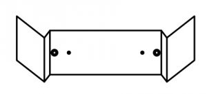 |
 |
|
2-2 NOTE TO THE INSTALLER
Be sure to instruct the customer how to properly operate the system showing him/her the attached operation manual.
3. REMOTE CONTROLLER INSTALLATION
<Installing wireless remote controller>
- Do not throw the remote controller or impose large shocks.
Also, do not store where it may be exposed to moisture or direct sunlight. - When operating, point the transmitting part of the remote controller in the direction of the receiver.
- The direct transmitting distance of the remote controller is approximately 23 ft..
- The signal cannot be transmitted if something such as curtains blocks the receiver and the remote controller.
- Installing to a wall or a pillar
- Fix the remote controller holder (3) with the screws (6).
- Slide the remote controller (2) into the remote controller holder (3) from the top.
- How to put the dry cell batteries
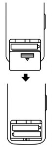
- Remove the back cover of the remote controller (2) to the direction pointed by the arrow mark.
- Put the dry cell batteries. Use two LR03 dry cell batteries (4). Put the dry cell batteries (4) correctly to fit their (+) and (–).
- Close the back cover as before.
4. RECEIVER INSTALLATION
CAUTION
- Do not install more than 3 receivers in the vicinity of one another.
- With 4 or more units, there is always the possibility of malfunction.
4-1. Preparations before installation
Remove the upper part of the receiver (1).
- Insert the screwdriver (–) here and gently work off the upper part of the receiver (1).
4-2. Determination of address and MAIN/SUB remote controller
If setting multiple wireless remote controllers to operate in 1 room, perform address setting for the receiver and the wireless remote controller. If setting multiple wired remote controllers in 1 room, change the MAIN/SUB switch of the receiver.
4-3. Setting procedure
- Setting the receiver
Set the wireless address switch (SS2) on the PC-board according to the table below.
| Unit No. | No.1 | No.2 | No.3 |
| Wireless address switch (SS2) | 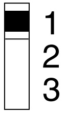 |
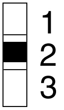 |
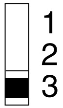 |
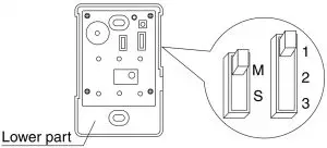
CAUTION
Change the setting so that the internal electronic equipments are not damaged with a pen etc.
When using both a wired and a wireless remote controller for 1 indoor unit, the wired controller should be set to MAIN.
Therefore, set the MAIN/SUB switch (SS1) of the receiver to SUB.
| MAIN | SUB | |
| MAIN/ SUB switch (SS1) |  |
 |
4-4. Receiver installation
WARNING
Be sure to turn off the power before installation.
CAUTION
<Precautions on transmission wiring>
- When wiring, run the wiring away the power supply wiring in order to avoid receiving electric noise (external noise).
- When wiring, refer to the wiring diagram of indoor unit (attached to indoor unit) as well.
WIRING SPECIFICATION
| Wiring type | Sheathed wire (2 wire) |
| Size | AWG18-16 |
| Wiring length | Max 650 ft. (See Note) |
NOTE
Keep wires to less than 650 ft. total when using 2 remote controllers (wired or wireless) and when not.
4-5. Attaching the receiver (for ceiling installation)
- Prepare the ceiling for the receiver.
- Open a hole in the ceiling for the receiver. (Use paper pattern printing (9)).
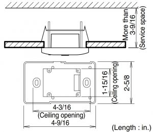
- Open a hole in the ceiling for the receiver. (Use paper pattern printing (9)).
- Wire the indoor unit and fix the lower part.
- Install the winged bar (10) to the lower part and fit the part with the screws (8). Then, wire (field supplied) accordingly. (Connect the P1 and P2 terminals on the rear of the lower part to the P1 and P2 terminals on the indoor unit. The P1 and P2 terminals have no polarity.)
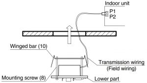
- Insert the lower part into the opening in the ceiling, first by pressing the wings inward to fit the hole and then by pushing from the screws (8) until it sits flat on the ceiling.
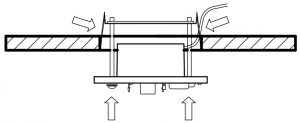
- Tighten the screws (8) until the lower part is fixed in place.
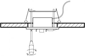
(Tighten both screws (8) evenly. Overtightening may deform the case and possibly make it harder to install the upper part.) - Attach the upper part of receiver (1).
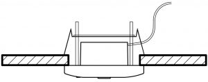
(Install the upper part on the lower part being careful parts are facing in the correct direction. After installation,turn on the power, and test emergency run button.)
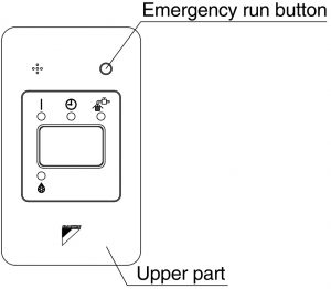
- Install the winged bar (10) to the lower part and fit the part with the screws (8). Then, wire (field supplied) accordingly. (Connect the P1 and P2 terminals on the rear of the lower part to the P1 and P2 terminals on the indoor unit. The P1 and P2 terminals have no polarity.)
4-6 Attaching the receiver (for wall mounting)
- Wire the indoor unit.
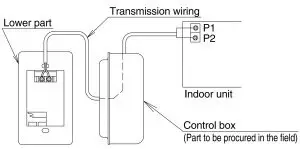
(Connect the P1 and P2 terminals on the rear of the lower part to the P1 and P2 terminals on the indoor unit. Neither of the terminals is polarized, so it is not important if connections are crossed.) - Fix the lower part.
- Install the lower part on the control box (field supplied part). (Select as flat a place as possible to install the lower part. Also, be aware of the fact that over tightening the screws (7)may deform the case and possibly make it harder to install the upper part.)
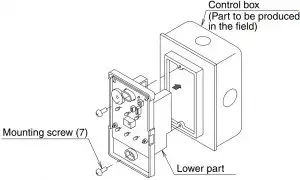
- Install the lower part on the control box (field supplied part). (Select as flat a place as possible to install the lower part. Also, be aware of the fact that over tightening the screws (7)may deform the case and possibly make it harder to install the upper part.)
- Attach the upper part of remote controller.
(Install the upper part on the lower part being careful parts are facing in the correct direction. After installation, turn on the power, and test emergency run button.)
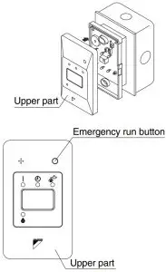
NOTE
- The control box and wiring are not included.
- Do not directly touch the PC-board with your hand.
4-7. Setting the address of wireless remote controller (It is factory set to “1”.)
<Setting from the remote controller>
- Hold down the “
 ” button and the “
  ” button for at least 4 seconds to get the FIELD SET MODE. (Indicated in the display area in the figure at top.)
 - Press the “
 ” button and select a multiple setting (A/b). Each time the button is pressed the display switches between “A” and “b”.
 - Press the “
 ” button and “
  ” button to set the address.
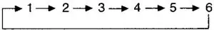
Address can be set from 1 to 6, but set it from 1 to 3 and to same address as the receiver. (The receiver does not work with address from 4 to 6.) - Press the “
 ” button to enter the setting.
 - Push the “ ” button to quit the FIELD SET MODE and return to the normal display.
<Multiple settings A/b>
When the indoor unit is being operating by outside control (central remote controller, etc.), it sometimes does not respond to ON/OFF and temperature setting commands from this remote controller. Check what setting the customer wants and make the multiple setting as shown below.
| Remote controller | Indoor unit | ||
| Multiple setting | Remote controller display | To control other air conditions and units | For other than on left |
| A: Standard | All items dis- played. | Commands other than ON/OFF and temperature setting accepted. (1 LONG BEEP or 3 SHORT BEEPS emitted) | |
| b: Multi System | Operations remain displayed shortly after execution | All commands accepted. (2 SHORT BEEPS) | |
4-8. Stick the Unit No. label on the receiver and the back of the wireless remote controller.
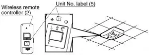
CAUTION
Set the Unit No. of the receiver and the wireless remote controller to be equal. If the settings differ, the signal from the remote controller cannot be transmitted.
5. FIELD SETTING
If optional accessories are mounted on the indoor unit, the indoor unit setting may have to be changed. Refer to the instruction manual (optional hand book ) for each optional accessory.
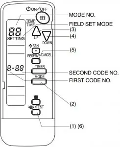
Procedure
- When in the normal mode, press the “ ” button for at least 4 seconds, and the FIELD SET MODE is entered.
- Select the desired MODE NO. with the “
 ” button.
 - Push the “ ” button and select the FIRST CODE NO..
- Push the “ ” button and select the SECOND CODE NO..
- Push the“ ”button and the present settings are set.
- Push the “ ” button to quit the FIELD SET MODE and return to the normal display
| MODE NO. | FIRST CODE NO. | DESCRIPTION OF SETTING | |
| 10 | 0 | Filter Contamination-Heavy/Light (Setting for spacing time of display time to clean air filter) (Setting for when filter contamination is heavy, and spacing time of display time to clean air filter is to be halved) | Long-life type |
| Standard type | |||
| 3 | Spacing time of display time to clean air filter count (Setting for when the filter sign is not to be displayed) | ||
| 12 (VRV system) | 1 | ON/OFF input from outside (Set to enable starting/ stopping from remote.) | |
| 2 | Thermostat differential changeover (Set when using remote controller thermostat sensor.) | ||
| MODE NO. | FIRST CODE NO. | SECOND CODE NO. | ||||
| 01 | 02 | 03 | ||||
| 10 | 0 | Light | Approx. 2,500 hours | Heavy | Approx. 1,250 hours | — |
| Approx. 200 hours | Approx. 100 hours | |||||
| 3 | Display | Do not display | — | |||
| 12 (VRV system) | 1 | Forced OFF input | ON/OFF | — | ||
| 2 | 2°F | 1°F | — | |||
NOTE
The SECOND CODE NO. is factory set to “01”.
Do not use any settings not listed in the table.
For group control with a wireless remote controller, initial settings for all the indoor units of the group are equal. (For group control, refer to the installation manual attached to the indoor unit for group control.)
6. TEST OPERATION
- Perform test operation according to the instructions in the installation manual attached to the indoor unit.
- After refrigerant piping, drain piping, and electric wiring, operate according to the table to protect the unit.
CAUTION
- Refer to a malfunction code in the installation manual attached to the outdoor unit if it does not operate.
- Refer to the installation manual attached to the outdoor unit for individual operation system types.
| Order | Operation |
| (1) (2) (3) (4) (5) (6) (7) (8) |
Open gas side stop valve. Open liquid side stop valve. Electrify crank case heater for 6 hours. Set to cooling with the remote controller and push “  ” button to start operation. ” button to start operation.Push“ ”button twice and operate in TEST OPERA- TION MODE for 3 minutes.Push“ 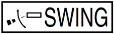 ”button and confirm its operation. ”button and confirm its operation.Push“ ”button and operate normally.Confirm its function according to the operation manual. |