Introduction
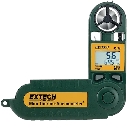
Congratulations on your purchase of Extech’s Model 45158 Anemometer. The dual display indicates Air Velocity and Humidity, Dew Point, Ambient Temperature, or Temperature with wind-chill factor. With careful use, this meter will provide years of reliable service.
Operation
Turning the meter ON and OFF
- Press the ON/OFF/HOLD button to turn the meter ON
- Press and hold the ON/OFF/HOLD buttons for approx. 3 seconds to turn it OFF
- The meter’s Auto Power OFF feature turns the meter OFF after 20 minutes of inactivity
Change the lower display parameter
- With the meter ON, press and hold down the ON/OFF/HOLD button
- While continuing to hold the ON/OFF/HOLD button, press the UNITS/MODE button repeatedly to step through Temperature (oF/oC), Humidity (RH%), Dew Point (TD), & Temperature with wind-chill factor (WCI). Note that the center display is Air Velocity.
Change the Air Velocity unit of measure
- Turn the meter OFF. Press and hold down both buttons until the display turns on and begins blinking then release both buttons
- Press the UNITS/MODE button repeatedly to step through the units (see specs for list)
- After 5 seconds the meter switches back to normal operation mode automatically
Select temperature units (oC or oF)
- Turn the meter OFF first. Press and hold down both buttons until the display turns on and begins blinking then release the buttons
- Press both buttons momentarily to change temperature units
- After 5 seconds the meter switches back to normal operation mode automatically
Taking Measurements
- Position the meter so that the airflow enters the meter vane from the rear of the meter (opposite side of front panel logo). A tripod mount is located on the bottom of the meter.
Max Hold
- Max Hold represents the highest measurement taken since the meter was turned on
- Press the UNITS/MODE button to display the Max reading (MAX icon appears)
- Press the UNITS/MODE button repeatedly to step through to the normal operating mode
Average mode
- 5 or 10 reading averages can be displayed in the Average Mode.
- Press UNITS/MODE 3 times for 5 reading averaging or 4 times for 10 readings
- To exit this mode, press the UNITS/MODE button until the icons on the left disappear
Data Hold
- Data Hold freezes the most recent displayed reading
- Press and hold the ON/OFF/HOLD button to activate Data Hold
- As long as the ON/OFF/HOLD button is held the reading will remain on the LCD
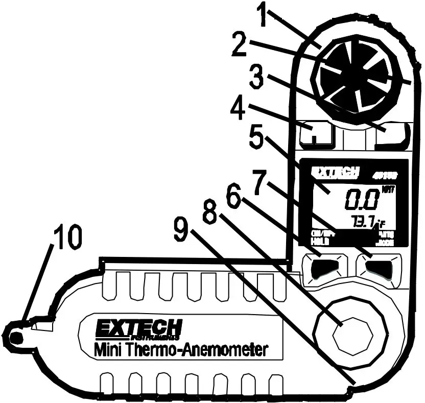
Meter Description

- Vane impeller
- Impeller set screw (on rear of meter)
- Relative Humidity sensor
- Temperature sensor
- LCD display
- ON/OFF, HOLD key
- UNITS, MODE key
- Battery compartment (on rear)
- Tripod mounting hole
- Lanyard (neckstrap)
Specifications
| Measurement | Range | Resolution | Accuracy (% of reading) |
| MPH (Miles per hour) | 2.5 to 44.7 MPH | 0.2 MPH | ± (3% + 0.4 mph) |
| km/hr (kilometers per hour) | 4.0 to 72.0 km/h | 0.7 km/h | ± (3% + 1.4 km/hr) |
| Knots (nautical miles per hour) | 2.1 to 38.9 knots | 0.3 knots | ± (3% + 0.6 knots) |
| m/sec (meters per second) | 1.1 to 20.0 m/s | 0.1 m/s | ± (3% + 0.2 m/s) |
| ft/min (feet per minute) | 216 to 3936 ft/min | 20ft/min | ± (3% + 40 ft/min) |
| Beaufort force | 1 to 8 BF | 1 BF | ± 1 |
| Temperature | 0 to 122oF (-18 to 50oC) | 0.1oF/C | ± 1.8oF (± 1oC) |
| Relative Humidity | 10 to 95% | 1% | ± 5% RH |
| Dew Point | 32 to 122 oF (0 to 50oC) | 0.1oF/C | ± 3.6oF (2oC) |
General Specifications
| Display | Dual LCD with low battery and multifunction indicators |
| Sensors | Sapphire bearing, non-corrosive vane for air velocity; Precision thermistor for temperature measurements |
| Average Mode | Choice of 5 or 10 reading averaging (2 second factory default) |
| Max and Data Hold Displays | Max recalls the highest reading; Data Hold freezes the display |
| Sample time | 1 reading per second for air velocity and temperature (1 reading per 15 seconds for humidity with 2 second updates) |
| Water-resistant | To 3’(1m) |
| Operating conditions | 5 to 122oF (-15 to 50oC) / < 80% RH |
| Power supply | Lithium battery (CR-2032 or equivalent) / 400 hour battery life |
| Dimensions / Weight |
|
Maintenance
Battery Replacement
The 45158 has a low battery indicator (battery symbol). Important: Turn the meter off before opening the battery compartment. Using a coin, turn the battery compartment cover CLOCKWISE to remove it. Once opened, observe the position of the battery, placing the new one in the same position. Secure the battery compartment cover and dispose of the lithium battery in accordance with local, state, or national disposal codes.
All EU users are legally bound by the Battery Ordinance to return all used batteries to community collection points or wherever batteries / accumulators are sold.
Disposal in household trash or refuse is prohibited.
 Disposal: Follow the valid legal stipulations in respect of the disposal of the device at the end of its lifecycle.
Other Battery Safety Reminders
- Never dispose of batteries in a fire. Batteries may explode or leak.
- Never mix battery types. Always install new batteries of the same type.
Impeller Replacement
- Remove the set screw next to the impeller assembly (on the rear of the meter).
- Twist the impeller assembly counter-clockwise to the OPEN position and remove it.
- Install impeller by inserting & twisting the new impeller assembly clockwise
- Tighten the set screw.
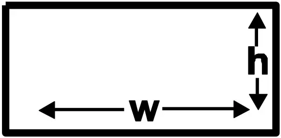
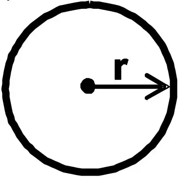
CFM Measurements
Measure the area of the duct using the diagrams below for rectangular and circular ducts (If the duct measurements are made in inches, divide the inches by 144 to get the area in square feet). Plug the area value (in square feet) in the cubic equations below. Note that the air velocity must be plugged into the cubic equations also.

A = w * h
A = πr²
- CFM (ft³/min) = Air Velocity (ft/min) x Area (ft²)
- CMM (m³/min) = Air Velocity (m/sec) x Area (m²) x 60
Warranty
Two-year Warranty
FLIR Systems, Inc. warrants this Extech brand instrument to be free of defects in parts and workmanship for two years from date of shipment (a six-month limited warranty applies to sensors and cables). To view the full warranty text please visit: http://www.extech.com/support/warranties.
Calibration and Repair Services
FLIR Systems, Inc. offers calibration and repair services for the Extech brand products we sell. We offer NIST traceable calibration for most of our products. Contact us for information on calibration and repair availability, refer to the contact information below. Annual calibrations should be performed to verify meter performance and accuracy. Product specifications are subject to change without notice. Please visit our website for the most up-to-date product information: www.extech.com
Contact Customer Support
Customer Support Telephone List: https://support.flir.com/contact
Calibration, Repair, and Returns: [email protected]
Technical Support: https://support.flir.com
Copyright © 2013- 2020 FLIR Systems, Inc.
All rights reserved including the right of reproduction in whole or in part in any form
www.extech.com
Digital Multimeter
MODEL EX410A
USER MANUAL

Introduction
Congratulations on your purchase of the Extech EX410A Multimeter. This meter measures AC/DC voltage, AC/DC Current, Resistance, Diode Test, and Continuity plus Thermocouple Temperature. This device is shipped fully tested and calibrated and, with proper use, will provide years of reliable service. Please visit our website (www.extech.com) to check for the latest version of this User Guide, Product Updates, additional user manual languages, and Customer Support.
Safety
International Safety Symbols


CAUTION
- Improper use of this meter can cause damage, shock, injury, or death. Read and understand this user manual before operating the meter.
- Always remove the test leads before replacing the battery or fuses.
- Inspect the condition of the test leads and the meter itself for any damage before operating the meter. Repair or replace any damaged before use.
- Use great care when making measurements if the voltages are greater than 25VAC rms or 35VDC. These voltages are considered a shock hazard.
- Warning! This is class A equipment. This equipment can cause interference to devices in the home; in this case, the operator can be required to carry out adequate measures to prevent interference.
- Always discharge capacitors and remove power from the device under test before performing Diode, Resistance or Continuity tests.
- Voltage checks on electrical outlets can be difficult and misleading because of the uncertainty of connection to the recessed electrical contacts. Other means should be used to ensure that the terminals are not “live”.
- If the equipment is used in a manner not specified by the manufacturer, the protection provided by the equipment may be impaired.
- This device is not a toy and must not reach children’s hands. It contains hazardous objects as well as small parts that children could swallow. In case a child swallows any of the parts, please contact a physician immediately.
- Do not leave batteries and packing material unattended; they can be dangerous for children.
- In case the device is going to be unused for an extended period of time, remove the batteries to prevent them from draining.
- Expired or damaged batteries can cause cauterization on contact with skin. Always use suitable hand protection.
- See that the batteries are not short-circuited. Do not throw batteries into fire.
OVERVOLTAGE CATEGORY III
This meter meets the IEC 61010-1 (2010) 3 rd edition standard for OVERVOLTAGE CATEGORY III. Cat III meters are protected against overvoltage transients in a fixed installation at the distribution level. Examples include switches in the fixed installation and some equipment for industrial use with permanent connection to the fixed installation.
SAFETY INSTRUCTIONS
This meter has been designed for safe use, but must be operated with caution. The rules listed below must be carefully followed for safe operation.
- NEVER apply a voltage or current to the meter that exceeds the specified maximum:
Input Protection Limits Function Maximum Input V DC or V AC 600V DC/AC, 200Vrms on 200mV range mA DC 200mA 600V fast-acting fuse A DC 10A 600V fast-acting fuse (30 seconds max every 15 minutes) Ohms, Continuity 250Vrms for 15sec max - USE EXTREME CAUTION when working with high voltages.
- DO NOT measure voltage if the voltage on the “COM” input jack exceeds 600V above earth ground.
- NEVER connect the meter leads across a voltage source while the function switch is in the current, resistance, or diode mode. Doing so can damage the meter.
- ALWAYS discharge filter capacitors in power supplies and disconnect the power when making resistance or diode tests.
- ALWAYS turn off the power and disconnect the test leads before opening the covers to replace the fuse or battery.
- NEVER operate the meter unless the back cover and the battery cover is in place and fastened securely.
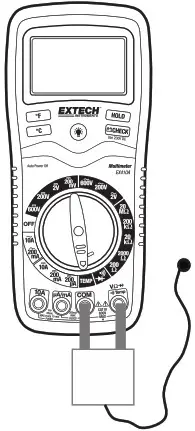
Description
- Rubber holster (must be removed to access battery2. 2000 count LCD display
- °F button for temperature measurements
- °C button for temperature measurements
- Function switch
- mA, uA and A input jacks
- COM input jack
- Positive input jack
- Battery check button
- Hold button (freezes displayed reading)
- LCD backlight button
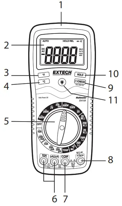
Note: Tilt stand, test lead holders, and battery compartment are on the rear of the unit.
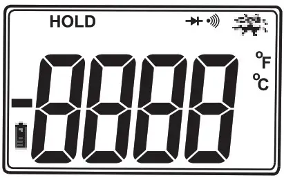
Symbols and Annunciators
| Continuity | |
| Diode test | |
 |
Battery status |
 |
Test lead connection error |
 |
Display hold |
 |
Degrees Fahrenheit |
 |
Degrees Celsius |
Operating Instructions
WARNING: Risk of electrocution. High-voltage circuits, both AC and DC, are very dangerous and should be measured with great care.
- ALWAYS turn the function switch to the OFF position when the meter is not in use.
- If “1” appears in the display during a measurement, the value exceeds the range you have selected. Change to a higher range.
NOTE: On some low AC and DC voltage ranges, with the test leads not connected to a device, the display may show a random, changing reading. This is normal and is caused by the high input sensitivity. The reading will stabilize and give a proper measurement when connected to a circuit.
DC VOLTAGE MEASUREMENTS
CAUTION: Do not measure DC voltages if a motor on the circuit is being switched ON or OFF. Large voltage surges may occur that can damage the meter.
- Set the function switch to the highest V DC (
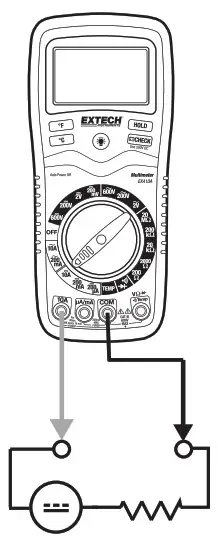 ) position.
 - Insert the black test lead banana plug into the negative COM jack. Insert the red test lead banana plug into the positive V jack.
- Touch the black test probe tip to the negative side of the circuit. Touch the red test probe tip to the positive side of the circuit.
- Read the voltage in the display. Reset the function switch to successively lower V DC positions to obtain a higher resolution reading. If the polarity is
reversed, the display will show (-) minus before the value.
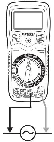
AC VOLTAGE MEASUREMENTS
WARNING: Risk of Electrocution. The probe tips may not be long enough to contact the live parts inside some 240V outlets for appliances because the contacts are recessed deep in the outlets. As result, the reading may show 0 volts when the outlet actually has voltage on it. Make sure the probe tips are touching the metal contacts inside the outlet before assuming that no voltage is present.
CAUTION: Do not measure AC voltages if a motor on the circuit is being switched ON or OFF.
Large voltage surges may occur that can damage the meter.
- Set the function switch to the highest V AC (
 ) position.
 - Insert the black test lead banana plug into the negative COM jack. Insert red test lead banana plug into the positive V jack.
- Touch the black test probe tip to the neutral side of the circuit. Touch the red test probe tip to the “hot” side of the circuit.
- Read the voltage in the display. Reset the function switch to successively lower V AC positions to obtain a higher resolution reading.
DC CURRENT MEASUREMENTS
CAUTION: Do not make current measurements on the 10A scale for longer than 30 seconds. Exceeding 30 seconds may cause damage to the meter and/or the test leads.
- Insert the black test lead banana plug into the negative COM jack.
- For current measurements up to 200µA DC, set the function switch to the 200µA DC () position and insert the red test lead banana plug into the uA/mA jack.
- For current measurements up to 200mA DC, set the function switch to the 200mA DC position and insert the red test lead banana plug into the uA/(mA jack.
- For current measurements up to 10A DC, set the function switch to the 10A DC range and insert the red test lead banana plug into the 10A jack.
- Remove power from the circuit under test, then open up the circuit at the point where you wish to measure current.
- Touch the black test probe tip to the negative side of the circuit. Touch the red test probe tip to the positive side of the circuit.
- Apply power to the circuit.
- Read the current in the display.
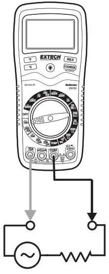
AC CURRENT MEASUREMENTS
CAUTION: Do not make current measurements on the 10A scale for longer than 30 seconds. Exceeding 30 seconds may cause damage to the meter and/or the test leads.
- Insert the black test lead banana plug into the negative COM jack.
- For current measurements up to 200mA AC, set the function switch to the highest 200mA AC () position and insert the red test lead banana plug into the mA jack.
- For current measurements up to 10A AC, set the function switch to the 10A AC range and insert the red test lead banana plug into the 10A jack.
- Remove power from the circuit under test, then open up the circuit at the point where you wish to measure current.
- Touch the black test probe tip to the neutral side of the circuit. Touch the red test probe tip to the “hot” side of the circuit.
- Apply power to the circuit.
- Read the current in the display.

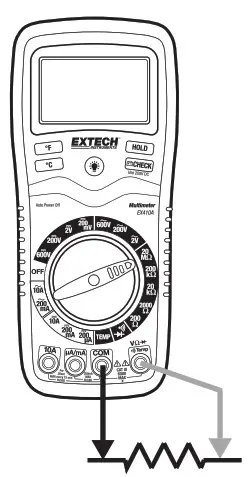
RESISTANCE MEASUREMENTS
WARNING: To avoid electric shock, disconnect power to the unit under test and discharge all capacitors before taking any resistance measurements. Remove the battery and unplug the line cords.
- Set the function switch to the highestΩ position.
- Insert the black test lead banana plug into the negative COM jack. Insert the red test lead banana plug into the positive Ω jack.
- Touch the test probe tips across the circuit or part under test. It is best to disconnect one side of the part under test so the rest of the circuit will not interfere with the resistance reading.
- Read the resistance in the display and then set the function switch to the lowest Ω position that is greater than the actual or any anticipated
resistance.
CONTINUITY CHECK
WARNING: To avoid electric shock, never measure continuity on circuits or wires that have voltage on them.
- Set the function switch to the
 position.
 - Insert the black lead banana plug into the negative COM jack. Insert the red test lead banana plug into the positive Ω jack.
- Touch the test probe tips to the circuit or wire you wish to check.
- If the resistance is less than approximately 150Ω, the audible signal will sound. If the circuit is open, the display will indicate “1”.
DIODE TEST
- Insert the black test lead banana plug into the negative COM jack and the red test lead banana plug into the positive diode jack.
- Turn the rotary switch to the position.
- Touch the test probes to the diode under test. Forward bias will typically indicate 400 to 1000. Reverse bias will indicate “1 ”. Shorted devices will indicate near 0 and the continuity beeper will sound. An open device will indicate “1 ” in both polarities.

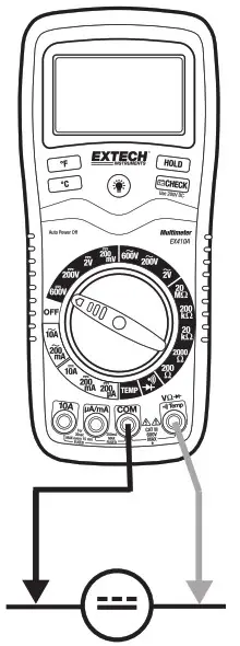
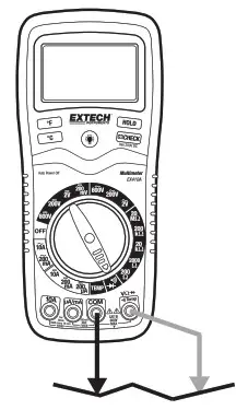
TEMPERATURE MEASUREMENTS
- Set the function switch to the TEMP position.
- Insert the Temperature Probe into the Temperature Socket, making sure to observe the correct polarity.
- Press the ºC or ºF button for the desired units.
- Touch the Temperature Probe head to the part whose temperature you wish to measure. Keep the probe touching the part under test until the reading stabilizes.
- Read the temperature in the display.
Note: The temperature probe is fitted with a type K mini connector. A mini connector to banana connector adaptor is supplied for connection to the
input banana jacks.

DISPLAY BACKLIGHT
Press and hold the  button to turn on the display backlight function. The backlight will automatically turn off after 15 seconds.
BATTERY CHECK
The CHECK function tests the condition of the 9V battery. Set the function switch to the 200VDC range and press the CHECK button. If the reading is less than 8.5, battery replacement is recommended.
HOLD
The hold function freezes the reading in the display. Press the HOLD key momentarily to activate or to exit the hold function.
AUTO POWER OFF
The auto-off feature will turn the meter off after 15 minutes.
LOW BATTERY INDICATION
If the ![]() icon appears in the display, the battery voltage is low and the battery should be replaced.
icon appears in the display, the battery voltage is low and the battery should be replaced.
WRONG CONNECTION INDICATION
The icon will appear in the upper right corner of the display and the buzzer will sound whenever the positive test lead is inserted into the 10A or uA/mA input jack and a non-current (green) function is selected. If this occurs, turn the meter off and reinsert the test lead into the proper input jack for the function selected.
Specifications
| Function | Range | Resolution | Accuracy | ||||
| DC Voltage (V DC) | 200mV | 0.1mV | ±(0.3% reading + 2 digits) | ||||
| 2V | 0.001V | ±(0.5% reading + 2 digits) | |||||
| 200V | 0.1V | ||||||
| 600V | 1V | ±(0.8% reading + 2 digits) | |||||
| AC Voltage (V AC) | 50 to 400Hz | 400Hz to 1 kHz | |||||
| 2V | 0.001V | ±(1.0% reading +6 digits | ±(2.0% reading + 8 digits | ||||
| 200V | 0.1V | ±(1.5% reading +6 digits | ±(2.5% reading +8 digits | ||||
| 600V | 1V | ±(2.0% reading +6 digits | ±(3.0% reading +8 digits | ||||
| DC Current (A DC) | 200pA | 0.1pA | ±(1.5% reading + 3 digits) | ||||
| 200mA | 0.1mA | ||||||
| 10A | 0.01A | ±(2.5% reading + 3 digits) | |||||
| AC Current (A AC) | 50 to 400Hz | 400Hz to 1kHz | |||||
| 200mA | 0.1mA | ±(1.8% reading +8 digits | ±(2.5% reading +10 digits) | ||||
| 10A | 0.01A | ±(3.0% reading +8 digits) | ±(3.5% reading +10 digits) | ||||
| Resistance | 2000 | 0.10 | ±(0.8% reading +4 digits) | ||||
| 20000 | 10 | ±(0.8% reading +2 digits) | |||||
| 20k0 | 0.01K2 | ±(1.0% reading +2 digits) | |||||
| 200k0 | 0.1k12 | ||||||
| 20M0 | 0.01M52 | ±(2.0% reading +5 digits) | |||||
| Temperature | -20 to 750°C | 1°C | ±(3.0% reading +3 digits) (meter only, probe accuracy not included) |
||||
| -4 to 1382°F | 1°F | ||||||
NOTE: Accuracy specifications consist of two elements:
- (% reading) – This is the accuracy of the measurement circuit.
- (+ digits) – This is the accuracy of the analog to digital converter.
NOTE: Accuracy is stated at 18°C to 28C (65°F to 83°F) and less than 75% RH.
General Specifications
Maintenance
WARNING: To avoid electrical shock, disconnect the meter from any circuit, remove the test leads from the input terminals, and turn OFF the meter before opening the case. Do not operate the meter with an open case.
This MultiMeter is designed to provide years of dependable service if the following care instructions are performed:
- KEEP THE METER DRY. If it gets wet, wipe it off.
- USE AND STORE THE METER IN NORMAL TEMPERATURES. Temperature extremes can shorten the life of the electronic parts and distort or melt plastic parts.
- HANDLE THE METER GENTLY AND CAREFULLY. Dropping it can damage the electronic parts or the case.
- KEEP THE METER CLEAN. Wipe the case occasionally with a damp cloth. DO NOT use chemicals, cleaning solvents, or detergents.
- USE ONLY FRESH BATTERIES OF THE RECOMMENDED SIZE AND TYPE. Remove old or weak batteries so they do not leak and damage the unit.
- IF THE METER IS TO BE STORED FOR A LONG PERIOD OF TIME, the batteries should be removed to prevent damage to the unit.
Battery Replacement
- Remove the Phillips head screw that secures the rear battery door
- Open the battery compartment
- Replace the 9V battery
- Secure the battery compartment
 Never dispose of used batteries or rechargeable batteries in household waste. As consumers, users are legally required to take used batteries to appropriate collection sites, the retail store where the batteries were purchased, or wherever batteries are sold.
Disposal: Do not dispose of this instrument in household waste. The user is obligated to take end-of-life devices to a designated collection point for the disposal of electrical and electronic equipment.
Other Battery Safety Reminders
- Never dispose of batteries in a fire. Batteries may explode or leak.
- Never mix battery types. Always install new batteries of the same type.
WARNING: To avoid electric shock, do not operate the meter until the battery cover is in place and
fastened securely.
NOTE: If the meter does not work properly, check the status of the fuses and batteries and ensuring proper insertion.
REPLACING THE FUSES
WARNING: To avoid electrical shock, disconnect the meter from any circuit, remove the test leads from the input terminals, and turn OFF the meter before opening the case. Do not operate the meter with an open case.
- Disconnect the test leads from the meter.
- Remove the protective rubber holster.
- Remove the battery cover (two “B” screws) and the battery.
- Remove the four “A” screws securing the rear cover.
- Lift the center circuit board straight up from the connectors to gain access to the fuse holders.
- Gently remove the old fuse and install the new fuse into the holder.
- Always use a fuse of the proper size and value (0.2A/600V fast blow (5x20mm) for the 200mA range, 10A/600V fast blow (6.3x32mm) for the 10A range).
- Align the centerboard with the connectors and gently press into place.
- Replace and secure the rear cover, battery, and battery cover.
WARNING: To avoid electric shock, do not operate your meter until the fuse cover is in place and fastened securely.
Copyright © 2013‐2016 FLIR Systems, Inc.
All rights reserved including the right of reproduction in whole or in part in any form
ISO‐9001 Certified
www.extech.com