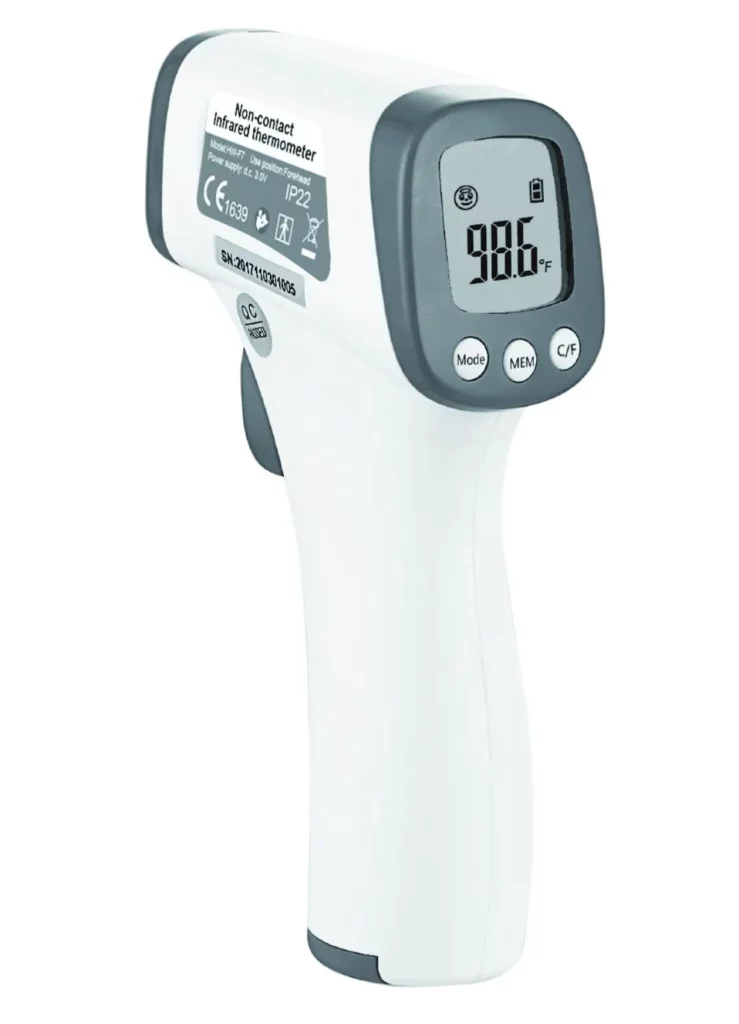
Model: HW-F7
 Heavy Duty Sensor
Compliant to IEC 60601-1, IEC60601-1-11, IEC 60601-1-2,
IEC 62304, ISO80601-2-56, ASTM E1965-98
Manual instruction
Please read this manual instruction thoroughly before use.
Version: V2.0 Date: 2020-06-08
Operating instructions
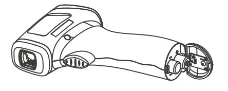
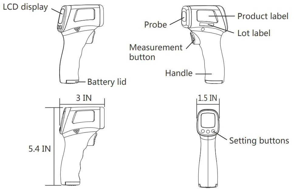
- Take out the thermometer and open the battery lid to install 2*AAA batteries
 Distinguish the positive and negative poles of the battery
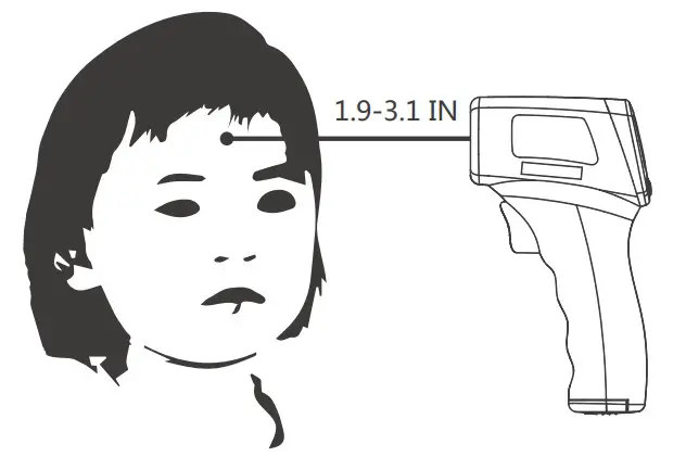
 - Keep distance at 5cm to 8cm from thermometer probe to the middle of the forehead, please do not contact forehead directly
- Select measurement mode and click the measurement button to start taking temperature
- Reading displays on the screen after successful measurement
Instruction Manual
Introduction & classification
This is a Non-Contact Forehead Thermometer applicable to forehead measurement. The thermometer measures body temperature by collecting heat radiation emitting from the forehead. A new probe structure is adopted in this thermometer. It’s simply operational, Hygeian, reliable, and highly accurate. Users can get a precise reading within one second with one touch. This thermometer is cost-effective and is widely used in schools, customs, hospitals, and for family use. Intended Use & Indication for use: The Non-Contact Forehead Thermometer is an infrared thermometer intended for the intermittent measurement of human body temperature in people of all ages.
This thermometer is classified as a Class IIa(for CE)/class II(for FDA) Medical Device, sorted as internally-powered equipment and type BF application device. It’s prohibited to use this thermometer in flammable anesthetic gas or gas mixture of air and oxygen or nitrous oxide. This is continuous operation equipment.
Working principle
Any object can generate a certain proportion of infrared radiant energy as per its own temperature. The radiant energy and its wavelength distribution are subjected to its surface temperature. Based on this principle, this thermometer is designed to detect infrared radiation at 5~14um by a highly precise infrared sensor. By adopting this high
quality sensor plus special calculation and calibration, this thermometer is able to take accurate body temperature
Safety precautions
 Warning:
- Using this thermometer is not intended as a substitute for consultation with your physician. It is dangerous for users to perform a self-evaluation and self-treatment based on the measuring result. please follow the doctor’s instructions.
- Keep the thermometer out of reach of children, please consult the doctor at once in case of accidental swallow of battery or another component.
- Don’t throw the battery into fire.
Notice:
- The device is a precision instrument, don’t drop, tramp or impose any vibration or impact on the thermometer.
- Do not touch the lens of the probe with your fingers and disassemble the device by yourself.
- Please make sure your forehead is clean before measuring forehead temperature.
- Please stay still indoors about 30 minutes after exercise, eating, or bathing before measuring.
- Please place the thermometer indoors for about 30 minutes if ambient temperature varies a lot before using.
- Please collect the record of Individual temperature under the good condition of the body on usual days as a reference for checking fever or not.
- Do not measure the sites of scarred tissue or tissue compromised by skin disorders because they will affect the accuracy of measurement.
- Do not measure if the patient is treated with certain drug therapies because the body temperature may rise in the drug within the effort time limit.
- Do not immerse the device in water or any other liquid, do not expose it to the sun.
- Do not use a mobile or cordless phone near the thermometer measuring. Do not use the thermometer near a mobile or cordless phone.
- Please don’t measure body temperature in a strong electromagnetic interference environment (such as microwave, high-frequency equipment operation environment) to ensure the accuracy of measurement data.
- This thermometer is only a personal device, please do not share with others.
- Please store the thermometer according to the technical specifications.
- Keep the sensor and probe cavity clean before use and after use.
- The materials (ABS) of contact with the patient have passed the ISO 10993-5 and ISO 10993-10 standard test, no toxicity, allergy and irritation reaction. They are compliant with the MDD requirements based on the current science and technology, and other potential allergic reactions are unknown.
The patient can measure, read data and replace the battery under normal circumstances and maintain the device and its accessories according to the user manual.
The PATIENT is an intended OPERATOR.
 Recommendations:
- Don’t use this thermometer for other purposes.
- It is forbidden to leave the product exposed to any chemical solvent, direct sunshine, or high temperature in case of damaging the product or the battery.
- Do not measure while talking on the phone.
- Please report to MANUFACTURER if any unexpected operation or events occur.
Features
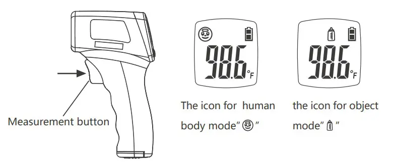
- Measurement model for human body and object available, one button to switch measurement mode;
- Beeper for high temperature;
- ℃/℉ reading available;
- Automatic shut off;
- Storage of last 10 readings;
- 3 Colors Backlight LCD for easy reading.
Technical parameters
| Measurement distance | 5cm -8cm | |
| Measurement | Human body | 34.0°C – 43.0°C (93.2°F -109.4°F) <34.0°C/93.2°F, “LO” displays >43.0°C/109.4°F, “HI” displays |
| Object | 0°C – 93°C (32.0°F -199.4°F) <0°C/32°F, “LO” displays >93°C/199.4°F, “HI” displays | |
| Measuring accuracy(at laboratory conditions) | for forehead temperature: +0.2°C/0.4°F during 34.0°C-42.0°C; +0.3°C/0.5°F during 42.1°C-43.0°C. |
|
| Resolution | 0.1°C/0.1°F | |
| Working condition | 15°C – 40°C ( 59.0°F -104°F ) RH <95%Non-condensing “ERR” displays when it’s not used under working condition |
|
| Storage condition | -25°C – 55°C (-13°F -131°F) RH <95%Non-condensing | |
| Power supply | d.c. 3V 2*AAA Batteries | |
| Power consumption | When offlOuW | |
| When measurement.5.30mW | ||
| Memory | Storage of last 10 readings | |
| Display | 3 Colors Backlight LCD (red, green, orange) | |
| Reading scale | Celsius or Fahrenheit | |
| Automatic shut off | In 30 seconds | |
| Dimensions | 5.4 INx3 IN x1.5 IN | |
| Net weight | 75g | |
| Shelf life | 5 Year | |
Illustration
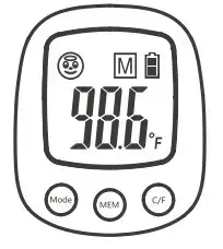
Display & icons
| Function definition | Icon | Details | |
| Battery level |  |
When it is visible | The battery is at a low level, but the thermometer is still functioning properly. Please replace battery asap |
| When it flashes | The battery is exhausted and the thermometer can not function properly. Please replace the battery immediately | ||
 |
When it is visible | Battery power is sufficient. and it functions properly. | |
| Measurement mode |  |
Human Body mode | |
 |
Object mode | ||
| Reading scale |  |
Celsius reading | |
 |
Fahrenheit reading | ||
| Reading display |  |
Temperature value | |
| Memory |  |
Temperature value of the previous measurement | |
Function definition of buttons
| Buttons | Description |
| Mode | To switch measurement mode between human body and object |
| MEM | To track the last 10 readings |
| C/F | To switch unit of temperature reading |
Setting
Users can change the reading scale between Celsius and Fahrenheit, and change measurement mode between human body mode and object mode.
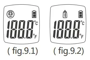
Measurement mode setting:
When the thermometer is on, it displays the current measurement mode ( fig.9.1). Press the “Mode” button to change measurement mode( fig.9.2).
 Reading scale setting:
When the thermometer is on, it displays the current Reading scale. Press the “C/F” button to select the reading scale.
Notice:
- The temperature under human body mode is obtained from dynamic compensation of environmental temp and forehead surface temp.
- Object temperature mode is to tests the surface temperature of an object. The temperature gets from the forehead under this mode is merely the temperature of the forehead surface but not body temperature.
Measurement
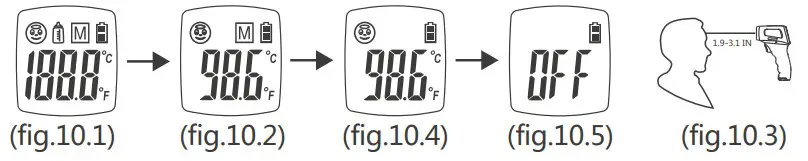
10.1 Body temperature
- Press the measurement button to turn on the thermometer and it displays the boot screen (fig.10.1). After POST and two beeps, it will display the value of the last reading and be ready for measurement (fig.10.2).
- Make sure the thermometer is in underbody mode.
- Keep distance at 5cm to 8cm from the thermometer probe to the middle of the forehead (fig.10.3). Press the measurement button and then it gives a beep to indicate measurement is finished and value will be displayed (fig.10.4). If the measurement value exceeds the alarm value(Defaulted value is 38℃), it gives a beep. beep. beep as an indication.
- After measurement, if the thermometer is idle for 30 seconds, it will display OFF (fig.10.5) and gives a beep, and shut off automatically.
10.2 Object temperature
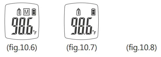
- Press the measurement button to turn on the thermometer (fig.10.6).
- Make sure the thermometer is under object mode.
- Keep vertical distance at 5cm to 8cm from object to measurement probe.
Press the measurement button and then it gives a“beep” to indicate measurement is finished and value will be displayed (fig.10.7). - After measurement, if the thermometer is idle for 30 seconds, it will display “OFF” (fig.10.8) and gives a “beep” and shut off automatically.
Notice:
- The value under this mode is objected surface temperature instead of core temperature.
- The default value of infrared emissivity is 0.95. The reading will deviate from the real temperature because of different emissivity. For example, the reading on stainless
steel is obviously lower than the real temperature. BE CAUTIOUS FOR SCALDING.
10.3 Exceeding measurement range
Body mode:
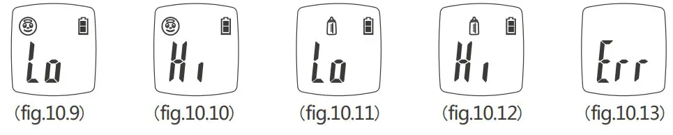
When the measurement value is lower than 34.0ºC(93.2℉), it displays Lo (fig.10.9) and gives“beep. beep.beep.beep”, with the color of backlight turning red.
When the measurement value is higher than 43.0 ºC(109.4℉), it displays Hi (fig.10.10) and gives“beep. beep.beep.beep”, with the color of the backlight turning red.
Object mode:
When the measurement value is lower than 0ºC(32℉), it displays Lo (fig.10.11) and gives “beep. beep.beep.beep”, with the color of backlight turning red.
When the measurement value is higher than 93ºC(199.4℉), it displays Hi (fig.10.12) and gives“beep. beep.beep.beep”, with the color of the backlight turning red.
Notice:
When the surrounding temperature is lower than 15.0ºC(59℉) or higher than 40.0ºC(104℉), it displays Err(fig.10.13) and gives “beep.beep.beep.beep”, with the color of backlight turning red.
Under this condition, it’s not allowed to use this thermometer, or accuracy is not assured.
Battery replacement
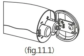
- Open the battery lid and take out the exhausted battery.
- Put into 2 AAA batteries and close up the battery lid. After the new battery is installed, the color of the backlight turns in the order of green, orange, and red, each of them
flashing one time respectively, with a “beep” heard. If no beep is heard, please check if the positive and negative pole is correct (see fig.11.1).
Notice:
- Take out the battery in case the thermometer is not used for a long time. Don’t put the battery to fire.
- Dispose of battery according to local regulations.
Maintenance & tips
- Make sure the sensor and probe cavity is clean otherwise it will affect accuracy.
Cleaning method for probe:
1. Use the cotton stick or soft cloth with water or alcohol to wipe the casing.
2. Use the cotton stick or soft cloth with alcohol to wipe the sensor surface or probe cavity gently. Don’t use a thermometer before alcohol is vaporized. - Read this manual book thoroughly before use. Make sure the battery is well installed.
It is not allowed to put the thermometer in any liquid or expose it to strong sunlight or extremely low temperature. - A strong crash or hit to the product will cause its damage.
- Do not dismantle this thermometer by yourself.
- Keep the thermometer from children’s reach.
- Do not use the thermometer under circumstances of strong electromagnetic interference.
- The measurement results are probably fluctuating due to improper measurement ways.
- Please practice adequate measurements in order to improve your skill.
- The measurement results can not supersede a doctor’s diagnosis.
- Special maintenance is unnecessary for this thermometer. Please contact the distributor or manufacturer in case of malfunction.
Troubleshooting
| Description | Solutions |
| LCD display “LO” or “HI” | 1. Breeze, water, sweating, cosmetics on the forehead may affect the measurement. 2. While if the testing environmental temp changes so enormously or if the thermometer is used directly from a high -temp object to a very low-temp one, the measurement difference will happen. The thermometer should be kept in a relatively stable environment for 10 minutes to get heat balance before starting a new measurement. 3. Ensure measurement distance is 5cm to 8cm. |
| No response when pressing the measurement button | 1. Take out and reassemble the battery. |
| No display or improper display | 1. Take out the battery and install the battery again. |
| Shut off right after switching on | 1. Check battery level or take out the battery and install the battery again. |
Standard list
| IEC 15223-1 | Symbols for use in the labeling of medical devices |
| EN 1041 | Information supplied by the manufacturer with medical devices |
| IEC 60601-1 | Medical electrical equipment Part 1: General requirements for basic safety and essential performance |
| IEC 60601-1-2 | Medical electrical equipment — Part 1-2: General requirements for basic safety and essential performance – Collateral standard: Electromagnetic compatibility – Requirements and tests |
| IEC 60601-1-6 | Medical electrical equipment — Part1-6: General requirements for basic safety and essential performance — Collateral standard: Usability |
| IEC 60601-1-11 | Medical electrical equipment —Part 1-11: General requirements for basic safety and essential performance—Collateral standard: Requirements for medical electrical equipment and medical electrical systems used in a home healthcare environment |
| ASTM E1965-98 | Standard Specification for Infrared Thermometer for Intermittent Determination of Patient Temperature |
| ISO 80601-2-56 | Medical electrical equipment part 2-56: particular requirements for basic safety and essential performance of clinical thermometer for body temperature measurement |
| IEC 62304 | Medical device software – Software life-cycle processes |
| IEC 62366 | Medical devices —Application of usability engineering to medical devices |
| ISO 10993-1 | Biological evaluation of medical devices – Part 1: Evaluation and testing within a risk management process |
Disposal
 Dispose of the device in accordance with the regulation applicable at the place of operation. Dispose of at public collection point in the EU countries – 2012/19/EU WEEE Directive.
If you have any queries, please refer to the local authorities responsible for waste disposal.
NOTES:
- Please act according to the native law to proceed to handle the battery and wastes.
- Take out the battery if you are not going to use the unit for a long time.
Dispose of empty batteries at your retail store or at appropriate collection sites
according to national or local regulations to protect the environment.
 Dispose of at public collection point in the EU countries – 2006/66/EC Directive.
Normalized symbols
 |
Read instruction manual before use |
 |
Type BF applied part |
 |
Batch |
 |
Serial number |
 |
Manufacturer information |
 |
Complies with the European Medical Device Directive(93/42/EEC and amended Directive 2007/47/EC. Notified Body is SGS |
 |
Complies with RoHS directive 2011/65/EU of the European Parliament and of the council of 8 June 2011 |
 |
Disposal in accordance with Directive 2012/19/EU (WEEE) |
 |
Follow operating instructions |
| IP22 | IP code of the device: this device’s grade of against ingress of solid foreign objects — 12.5mm diameter (and the against access to hazardous parts with finger); the grade of waterproof is dripping (15° tilted) |
EMC Declaration
- Use of this equipment adjacent to or stacked with other equipment should be avoided because it could result in improper operation. If such use is necessary, this equipment and the other equipment should be observed to verify that they are operating normally.
- Use of accessories, transducers, and cables other than those specified or provided by the manufacturer of this Infrared Thermometer could result in increased electromagnetic emissions or decreased electromagnetic immunity of this equipment and result in improper operation.
- Portable RF communications equipment (including peripherals such as antenna cables and external antennas) should be used no closer than 30 cm (12 inches) to any part of the Infrared Thermometer, including cables specified by the manufacturer.
Otherwise, degradation of the performance of this equipment could result.
Guidance and manufacturer´s declaration – electromagnetic emission – for all EQUIPMENT AND SYSTEMS
| Guidance and manufacturer’s declaration — electromagnetic emission | ||
| The infrared thermometer is intended for use in the electromagnetic environment specified below. The customer or the user of the infrared thermometer should assure that it is used in such an environment. |
||
| Emissions test | Emissions test | Electromagnetic environment – guidance |
| RF emissions CISPR 11 | Group 1 | The Infrared Thermometer uses RF energy only for its internal function. Therefore, its RF emissions are very low and are not likely to cause any interference in nearby electronic equipment. |
| RF emissions CISPR 11 | Class B | The Infrared Thermometer is suitable for use in all establishments, including domestic establishments and those directly connected to the public low-voltage power supply network that supplies buildings used for domestic purposes. |
| Harmonic emissions IEC 61000-3-2 |
N/A | |
| Voltage fluctuations flicker emissions IEC 61000-3-3 |
N/A | |
Guidance and manufacturer’s declaration – electromagnetic immunity –for all EQUIPMENT and SYSTEMS
Guidance and manufacturer´s declaration – electromagnetic emission
The infrared thermometer is intended for use in the electromagnetic environment specified below.
The customer or the user of the infrared thermometer should assure that it is used in such an environment.
| Immunity test | IEC 60601 test level | Compliance level | Electromagnetic environment-guidance |
| Electrostatic discharge (ESD) IEC 61000-4-2 |
± 8 kV contact ± 2 kV, ± 4 kV, ± 8 kV, ± 15 kV air |
± 8 kV contact ± 2 kV, ± 4 kV, ± 8 kV, ± 15 kV air |
Floors should be wood, concrete or ceramic tile. If floors are covered with synthetic material, the relative humidity should be at least 30 `YD. |
| Electrostatic transient / burst IEC 61000-4-4 |
± 2 kV for power supply lines ± 1 kV for input/output lines | N/A | The mains power quality should be that of a typical commercial or hospital environment. |
| Surge IEC 61000-4-5 |
± 1 kV differential mode ± 2 kV common mode |
N/A | The mains power quality should be that of a typical commercial or hospital environment. |
| Voltage dips, short interruptions, and voltage variations on power supply input lines IEC 61000441 |
0 % UT; 0,5 cycle g) At 0°, 45°, 90°, 135°, 180°, 225°, 270° and 315° 0 % UT; 1 cycle and 70 % UT; 5/30 cycles Single phase: at 0° 0 % UT; 250/300 cycle |
N/A | The mains power quality should be that of a typical commercial or hospital environment. If the user of the Infrared thermometer requires continued operation during power mains interruptions, it is recommended that the Infrared thermometer be powered from an uninterruptible power supply or a battery. |
| Power frequency (50/60 Hz) magnetic field IEC 61000-4-8 |
30 Nrn | 30 A/m | Power frequency magnetic fields should be at levels characteristic of a typical location in a typical commercial or hospital environment. |
NOTE UT is the a. c. mains voltage prior to application of the test level.
Guidance and manufacturer´s declaration – electromagnetic emission – for all EQUIPMENT AND SYSTEMS
| Guidance and manufacturer’s declaration — electromagnetic immunity | |||
| The infrared thermometer is intended for use in the electromagnetic environment specified below. The customer or the user of the infrared thermometer should assure that it is used in such an environment. |
|||
| Immunity test | IEC 60601 test level | Compliance level | Electromagnetic environment-guidance |
| Conducted RF IEC 61000-4-6 Radiated RF IEC 61000-4-3 |
3 Vrms 150 kHz to 80 MHz 6 V in ISM and amateur radio bands between 0,15 MHz and 80 MHz 10 V/m 80 MHz to 2.7 GHz 385MHz-5785M Hz Test specifications for ENCLOSURE PORT IMMUNITY to RF wireless communication equipment (Refer to table 9 of IEC 60601-1-2:2014) |
N/A 10 V/m 80 MHz to 2.7 GHz 385MHz-5785MHz Test specifications for ENCLOSURE PORT IMMUNITY to RF wireless communication equipment (Refer to table 9 of IEC 60601-1-2:2014) |
Portable and mobile communications equipment should be used no closer to any part of the Infrared thermometer, including cables, than the recommended separation distance calculated from the equation applicable to the frequency of the transmitter. Recommended separation distance 3.5
|
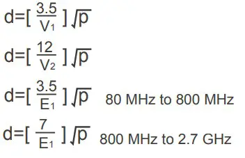 where p is the maximum output power rating of the transmitter in watts (W) according to the transmitter manufacturer and d is the recommended separation distance in meters (m).b
NOTE 1 At 80 MHz and 800 MHz, the higher frequency range applies.
NOTE 2 These guidelines may not apply in all situations. Electromagnetic is affected by absorption and reflection from structures, objects, and people.
a. The ISM (industrial, scientific and medical) bands between 150 kHz and 80 MHz are 6,765 MHz to 6,795 MHz; 13,553 MHz to 13,567 MHz; 26,957 MHz to 27,283 MHz; and 40,66 MHz to 40,70 MHz. The amateur radio bands between 0,15 MHz and 80 MHz are 1,8 MHz to 2,0 MHz, 3,5 MHz to 4,0 MHz, 5,3 MHz to 5,4 MHz, 7 MHz to 7,3 MHz, 10,1 MHz to 10,15 MHz, 14 MHz to 14,2 MHz, 18,07 MHz to 18,17 MHz, 21,0 MHz to 21,4 MHz, 24,89 MHz to 24,99 MHz, 28,0 MHz to 29,7 MHz and 50,0 MHz to 54,0 MHz.
b. Field strengths from fixed transmitters, such as base stations for radio (cellular/cordless) telephones and land mobile radios, amateur radio, AM and FM radio broadcast and TV broadcast cannot be predicted theoretically with accuracy.
To assess the electromagnetic environment due to fixed RF transmitters, an electromagnetic site survey should be considered. If the measured field strength in the location in which the Infrared thermometer is used exceeds the applicable RF compliance level above, the Infrared thermometer should be observed to verify normal operation. If abnormal performance is observed, additional measures may be necessary, such as reorienting or relocating the Infrared thermometer.
c. over the frequency range 150 kHz to 80 MHz, field strengths should be less than 3V/m.
Recommended separation distances between portable and mobile
RF communications equipment and the EQUIPMENT or SYSTEM -for
EQUIPMENT and SYSTEMS
Recommended separation distances between portable and mobile RF communications equipment and the Infrared thermometer
The Infrared thermometer is intended for use in an electromagnetic environment in which radiated RF disturbances are controlled. The customer or the user of the An infrared thermometer can help prevent electromagnetic interference by maintaining a minimum distance between portable and mobile RF communications equipment (transmitters) and the Infrared thermometer as recommended below, according to the maximum output power of the communications equipment
| Rated maximum output of the transmitter W |
Separation distance according to the frequency of the transmitter m |
|||
150 kHz to 80 MHz outside ISM and amateur radio bands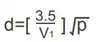 |
150 kHz to 80 MHz in ISM and amateur radio bands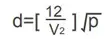 |
180 MHz to 800 MHz | 800 MHz to 2.7 GHz | |
| 0.01 | 0.12 | 0.20 | 0.035 | 0.07 |
| 0.1 | 0.38 | 0.63 | 0.11 | 0.22 |
| 1 | 1.2 | 2.00 | 0.35 | 0.70 |
| 10 | 3.8 | 6.32 | 1.10 | 2.21 |
| 100 | 12 | 20.00 | 35 | 70 |
For transmitters rated at a maximum output power not listed above the recommended separation distance d in meters (m) can be estimated using the equation applicable to the frequency of the transmitter, where P is the maximum output power rating of the transmitter in watts (W) according to the transmitter manufacturer.
NOTE 1 At 80 MHz and 800 MHz, the separation distance for the higher frequency range applies.
NOTE 2 These guidelines may not apply in all situations. Electromagnetic propagation is affected by absorption and reflection from structures, objects, and people.
Quality commitment
Company name: REED
Add:1601 WEST LAFAYETTE DETROIT, Michigan 48216 USA
Email: [email protected]
Tel:917-719-5114