USER MANUAL
XERUN XR10 Justock G3
XERUN XR10 Justock G3-Handout Spec
01. Disclaimer
Thank you for purchasing this HOBBYWING product! The power of brushless power system is powerful. Any improper use may cause personal injury and damage to the devices. Please read through this manual before use and strictly abide by the specified operating procedures. We shall not be liable for any liability arising from the use of this product, including but not limited to reimbursement for incidental or indirect losses. Meanwhile, we do not assume any responsibility caused by unauthorized modification of the product. We have the right to change the product design, appearance, performance and use requirements without notice.
02. Warnings
- Ensure all wires and connections are well insulated before connecting the ESC to r elated devices, as short cir cuit will damage your ESC.
- Ensure all devices are well connected, in or der to prevent poor connections that may cause your vehicle to lose cont rol or other unpredictable issues like damage to the device.
- Please carefully check power devices and manual of car frame to ensur e the power pairing is r easonable. Avoid wrong pairing to overload the motor and damage the ESC.
- Please use a soldering ir on with the power of at least 50W to solder all input/output wi res and connectors.
- Stop using the ESC when its outer temperatur e exceeds 90/194; otherwise your ESC will get destroyed and may also get your motor damaged.
- Always disconnect and r emove batteries after use, as the ESC will continue to consume current if it’s still connected to batteries (even if the ESC is tur ned off). Long-time contact will
cause batteries to completely discharge and result in damage to batteries or ESC or both. This will not be covered under warranty.)
03. Features
- The timing has been permanently set to 0 degree. With the identical competition motor, this ensures that every driver will have the same power system and have a really just race.
- Aluminum housing top with excellent heat dissipation and gr eat current endurance.
- The built-in capacitor avoids the trouble of finding installation position for the external capacitor module, saves space and is convenient for layout;
- The built-in reverse connection protection circuit prevents damaging ESC due to reverse connection of battery.
- The innovative capacitor overheat protection function can effectively avoid the capacitor explosion caused by overload and finally damage the ESC.
- Multiple protections: battery low-voltage cutoff protection, over temperature protection, fail safe (throttle signal loss protection) and motor lock-up protection.
- Supports multi-function LCD program box and OTA programmer to set parameters of ESC, which is convenient for outs ide use.
- Supports firmware upgrade of ESC (Multi-function LCD program box or OTA Programmer need to be pur chased), Enjoy the latest features permanently.
- Supports various RPM limit values to meet the needs of different races. It can be set directly by the program box or OTA programmer, which is simple and convenient.
04. Specifications

05. Connect ESC
Note: This is an extremely powerful brushless motor system. For your safety and the safety of those around you, we strongly recommend removing your pinion gear before performing calibration and programming functions with this system, and keeping wheels in the air when you turn on the ESC.
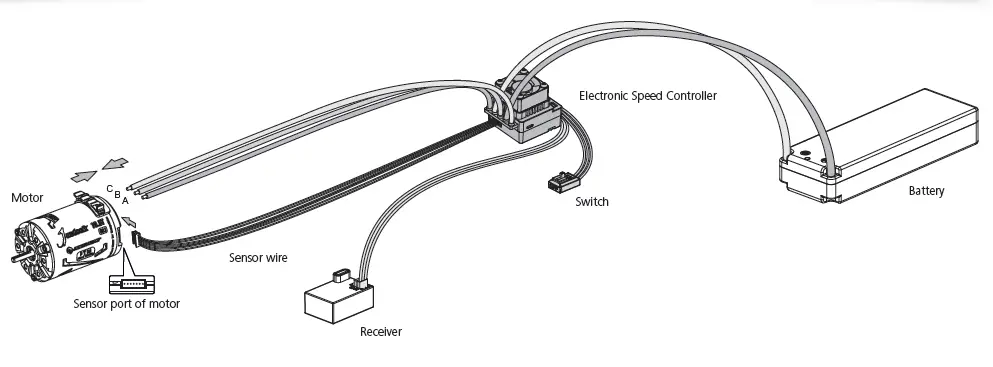
Please wire correctly according to wiring instructions and wiring diagram.
- Motor Wiring
The sensored motor wiring is a little different from the sensorless motor wiring; please make sure that you will strictly follow the introductions below.
A. Sensored Brushless Motor Wiring
There is strict wiring order from the ESC to the motor, the three A/B/C ESC wires must connect to the three A/B/C motor wires correspondingly and then connect the ESC sensor port
and the motor sensor port with the stock 6-pin sensor cable.
Note 1: If you don’t plug the sensor cable in, your ESC will still work in sensorless mode. It is like the ESC connects to sensorless brushless motor.
B. Sensorless Brushless Motor Wiring
There is no polarity on the A/B/C wires between ESC and motor, so do not worry about how you connect them initially. You may find it necessary to swap two wires if the motor runs in
reverse. - Receiver Wiring
Plug the throttle control cable (also called Rx cable) on the ESC into the throttle (TH) channel on receiver. So please do not supply power to the receiver. Otherwise, your ESC may be
damaged. - Battery Wiring
Connect the battery when the ESC is power off. Make sure positive (+) of ESC connects to positive (+) of battery, and negative (-) of ESC connects to negative (-) of battery when you
plug in your battery! Then turn on the ESC to run it.
06. ESC Setup
1. Set throttle range
You must reset throttle range when you begin to use a new ESC, or the transmitter changes the parameters such as the TRIM, D/R, EPA and other parameters, otherwise the ESC cannot work properly.
We strongly recommend to activate the “Fail Safe” function of the transmitter and set no signal protection for throttle channel of transmitter (F/S) to “OFF” or set its value to the “Neutral
Position” to ensure the motor can be stopped when there is no signal received from the transmitter. The throttle calibration steps is as follows:
- Turn on the transmitter, set parameters on the throttle channel like “D/R”, “EPA” and “ATL” to 100% (for transmitter without LCD, please turn the knob to the maximum) and the
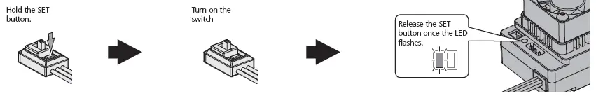
throttle “TRIM” to 0 (for transmitter without LCD, please turn the corresponding knob to the neutral position). - Turn off the ESC. Hold the SET button and turn on the ESC, the RED LED on the ESC starts to flash (the motor beeps at the same time), and then release the SET button immediately. (The
ESC will enter the programming mode if the SET button is not released in 3 seconds, then you need to restart from step 1.)
Note : Beeps from the motor may be low sometimes, and you can check the LED status instead.


3. Set the neutral point, the end position of forward and the end position of backward.
1) Leave the throttle trigger at the neutral position, press the SET button, the RED LED dies out and the GREEN LED flashes once and the motor beeps 1 time to store the neutral position.
2) Pull the throttle trigger to the end position of forward, press the SET button, the GREEN LED flashes twice and the motor beeps 2 times to store the end position of forward.
3) Push the throttle trigger to the end position of backward, press the SET button, the GREEN LED flashes 3 times and the motor beeps 3 times to store the end position of backward.
Note:
- The end position of forward: Pull the trigger to the maxim um throttle position if it is pistol-style transmitter . Push the throttle to the top if it is board-style transmitter .
- The end position of backward: Push the trigger to the maximum brake position if it is pistol-style transmitter. Pull the throttle to the bottom if it is board-style transmit ter.
4. The motor can work normally after the throttle range calibration is complete.
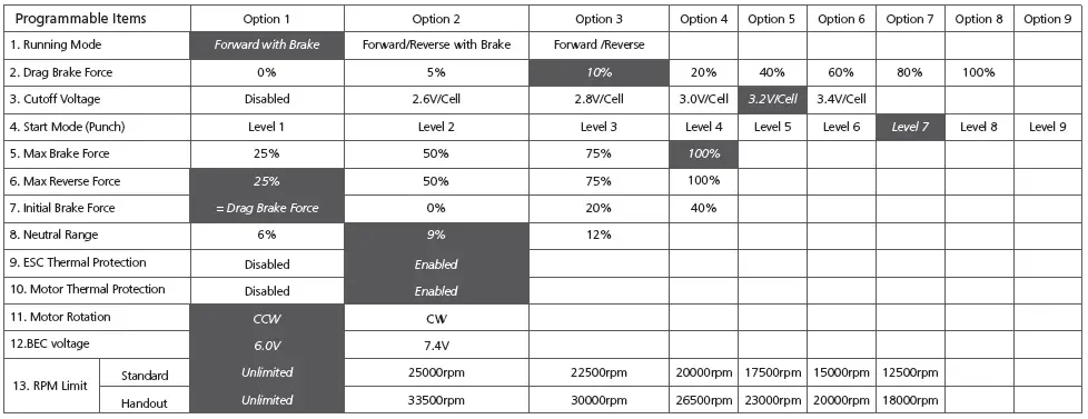
2. Programmable Items
Those “black background and white text” options are the factory default settings.
- Running Mode
Option 1: Forward with Brake
The vehicle can go forward and brake but cannot reverse in this mode. This mode is usually for racing.
Option 2: Forward/Reverse with Brake
This mode provides the braking function, it’s usually for training. “Forward/Reverse with Brake” mode adopted the “DOUBLE-CLICK” method, that is your vehicle only brakes (won’t reverse)
when the 1st time you push the throttle trigger from neutral zone to backward zone. If the motor stops when the throttle trigger quickly return to the neutral zone and then re-push the
trigger to backward zone, the vehicle will reverse. If the motor does not stop, then your vehicle won’t reverse but brake, you need to return the throttle trigger to the neutral zone and push
it to backward zone again. The vehicle only reverses after the motor stops. This method is for preventing vehicle from being accidentally reversed.
Option 3: Forward/Reverse
This mode used the “SINGLE-CLICK” method to make the car go backward. When you move the throttle trigger from neutral zone to backward zone, the car will go backward immediately. - Drag Brake Force
Drag brake is the braking power produced when releasing the throttle trigger to neutral zone. This is to simulate the resistance applied by carbon brush of the brush motor to rotator of
motor while coasting.(Attention! Drag brake will consume much power, so please apply it cautiously.) - Cutoff Voltage (or Low Voltage Cutoff Threshold)
The ESC will monitor the battery voltage all the time, on ce the voltage is lower than the threshold value, the ESC will reduce the power to 50% and cutoff the power output in 10
seconds. When enters into voltage pr otection, the RED LED will single flash that repeats (, , , …….). Please set the “Cutoff Voltage” to “Disabled” if you are using NiMH batteries. - Start Mode / Punch
You can choose the punch from level 1 (very soft) to level 9 (very aggressive) as per the track, tires gripping, your preference and etc. This feature is very useful for preventing tires from
slipping in the starting-up process. In addition, “level 7”, “level 8 and “level 9” have strict requirement on battery’s discharge capability. It may affect the starting-up if the battery
discharges poorly and cannot provide large current in a short time. The car stutters or suddenly loses power in the starting-up process indicating the battery’s discharge capability is not
good; you need to reduce the punch or increase the FDR (Final Drive Ratio). - Max. Brake Force
This ESC provides the proportional braking function; the braking effect is determined by the position of the throttle trigger. The max. brake force is produced when the throttle trigger is at the
brake bottom position. Please select the max. brake force parameter as per your car condition and your preference. - Max. Reverse Force
Different reverse amount will bring different reversing speed. For the safety of your vehicle, we recommend using a low amount. - Initial Brake Force
It also called min. brake force. It refers to the brake force applied to the motor at the initial position. It seems like point brake. The default value is equal to the drag brake force, so as to
form a soft brake effect. - Throttle Neutral Range
As not all transmitters have the same stability at “neutr al position”, please adjust this parameter as per your preference. You can adjust to a bigger value when this happens. - ESC Thermal Protection
The output from the ESC will be cut off with the value you have preset. The GREEN LED flashes (, , ) when the ESC temperature reaches to the preset value. The output will not
resume until the ESC temperature gets down.
Warning! Please do not disable this function unless you’re in a competition. Otherwise the high temperature may damage your ESC and even your motor. - Motor Thermal Protection
After enable this function, the output will be automatically closed when the motor temperature reaches the preset value. The green light flashes until the temperature drops to restore the
output. When the motor is overheated, the green light will flash twice in cycle.
Warning! Please do not disable this function unless you’re in a competition. Otherwise the high temperature may damage your motor and even your ESC. For non-Hobbywing
motor, the ESC may get this protection activated too early/late because of the different temperature sensor inside the motor. In this case, please disable this function and
monitor the motor temperature manually. - Motor Rotation
It is used to adjust the rotation direction of the motor (in CW or CCW), that is, when the forward throttle is given, and the rotation direction of the motor is reverse, it can be set to the
opposite direction. - BEC Voltage
The BEC voltage can be adjusted at 6.0V and 7.4V. The normal steering servo is generally set at 6.0V, and the high-voltage steering servo can be set at 7.4v. Select the appropriate voltage
according to the steering servo used. - RPM Limit
It is used to set the max. RPM value of the motor. Set corresponding values according to competition rules.
This parameter has two choices according to different versions of ESC used:
1. If use Hobbywing’s Standard ESCXR10 Justock G3, then select rpm limit of “Standard” in the table.
2. If use Hobbywing’s Handout ESCXR10 Justock G3-Handout Spec, then select rpm limit of “Handout” in the table.
3. ESC Programming
1. Programming your ESC with the SET button

Note:
- For easy recognition, the motor beeps at the same time when the LED flashes.
- When “N” (the number) is equal to/bigger than 5, we use a long flash to represent “5”. For example, the GREEN LED flashes a long flash (and the motor beeps a long beep at the same time) indicating you are in the 5th programmable item; if the GREEN LED flashes a long flash and a short flash (and the motor beeps a long beep and a short beep at the same time) indicating you are in the 6th programmable item; a long flash and two short flashes ( a long beep and two short beeps at the same time) indicating you’re in the 7th programmable item and so on.
2. Program your ESC with a LCD program box
(For detailed information, please refer to the user manual of the LCD program box.)
You can use LCD program box to set parameters, or connect LCD program box with computer to set parameters (use HOBBYWING USB LINK software). Connect the ESC and LCD program box via a cable with two JR male connectors. Then power on the ESC, the LCD setting box will display the boot interface. Press any key on the LCD program box to set up communication between the LCD program box and the ESC, and displaying “CONNECTING ESC”. After several seconds, the current mode name will be displayed, and the first setting parameter will be displayed after that. Press “ITEM” and “VALUE” button to change the parameters. Press “OK” button to store the parameters to your ES.
3. Program your ESC with a OTA Programmer
Plug the programming cable of OTA Programmer to the programming port of ESC. Then use the mobile phone to install HOBBYWING HW LINK App to set parameters

4. Factory Reset
1) Restore the default values with the SET button Press and hold the SET button for over 3 seconds anytime when the throttle trigger is at the neutral position (except during the ESC calibration and programming) can factory reset your ESC. RED & GREEN LEDs flash simultaneously indicating you have successfully restored all the default values within your ESC. Once you power the ESC off, and then back on, your settings will be back in the default mode.
2) Restore the default values with a multifunction LCD program box After connecting the program box to the ESC, continuously press the “ITEM” button on the program box until you see the “RESTORE DEFAULT” item, and then press “OK” to factory reset your ESC.
3) Restore the default values with a OTA Programmer(Use HW LINK mobile phone App) Connect OTA Programmer to the ESC, enter into [Parameters], click “reset” to factory reset your ESC.
07. Explanations for Different Status LED
- The throttle is in neutral zone
1) In normal Blinky mode (non-rpm limit mode), the red LED flashes rapidly.
2) In the RPM limit mode, there are two different flashing modes due to two versions of XR10-Justock G3 and XR10-Justock G3 Handout Spec, the details are as follows:
XR10-Justock G3:
In RPM limit mode, when RPM limit is 25,000, the red LED long flashes once and the green LED flashes once.
In RPM limit mode, when RPM limit is 22,500, the red LED long flashes once and the green LED flashes twice.
In RPM limit mode, when RPM limit is 20,000, the red LED long flashes once and the green LED flashes three times.
In RPM limit mode, when RPM limit is 17,500, the red LED long flashes once and the green LED flashes four times.
In RPM limit mode, when RPM limit is 15,000, the red LED long flashes once and the green LED flashes five times.
In RPM limit mode, when RPM limit is 12,500, the red LED long flashes once and the green LED flashes six times.
XR10-Justock G3 Handout Spec:
In RPM limit mode, when RPM limit is 33,500, the green LED long flashes once and the red LED flashes once.
In RPM limit mode, when RPM limit is 30,000, the green LED long flashes once and the red LED flashes twice.
In RPM limit mode, when RPM limit is 26,500, the green LED long flashes once and the red LED flashes three times.
In RPM limit mode, when RPM limit is 23,500, the green LED long flashes once and the red LED flashes four times.
In RPM limit mode, when RPM limit is 20,000, the green LED long flashes once and the red LED flashes five times.
In RPM limit mode, when RPM limit is 18,000, the green LED long flashes once and the red LED flashes six times. - The throttle is in non-neutral zone
1) The RED LED turns on solid when moving forward. Green LED is also on when throttle trigger is at the end position of forward100% throttleon non-speed limit mode).
2) The RED LED turns on solid when you brake. The GREEN LED will also come on when pushing the throttle trigger to the full brake endpoint and setting the “Max. Brake Force” to 100%.
3) The RED LED turns on solid when you reverse your vehicle. - LED status when some Protection is Activated:
1) The RED LED flashes a short, single flash that repeats indicating the low voltage cutoff protection is activated.
2) The GREEN LED flashes a short, single flash that repeats indicating the ESC thermal / overheat protection is activated.
3) The GREEN LED flashes a short, double flash that repeats indicating the motor thermal /overheat protection is activated.
4) The GREEN LED flashes a short, five times flash that repeats) indicating the capacitor thermal /overheat protection is activated.
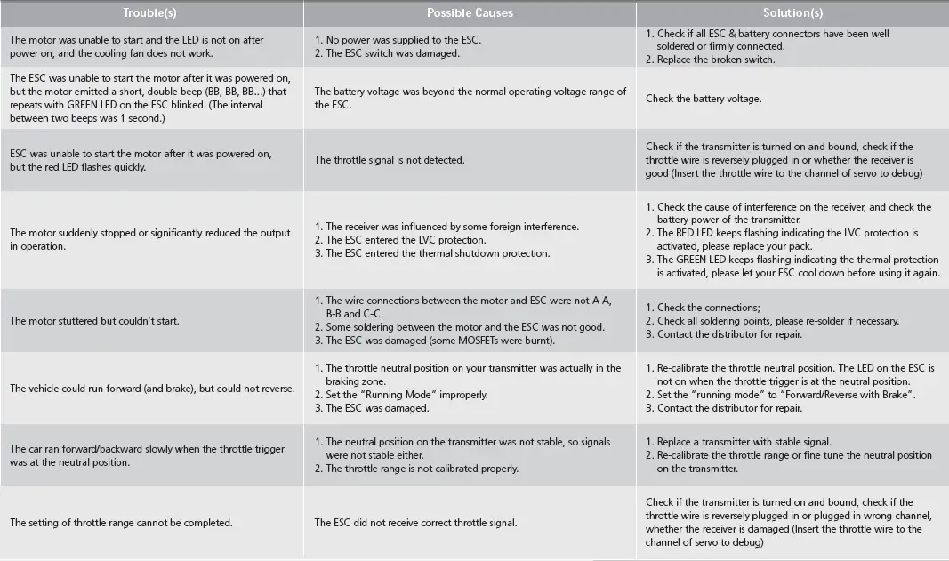
08. Trouble Shooting