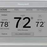
Honeywell Home TH6220WF2006 PRO T6 Smart Programmable Thermostat

Honeywell Home TH6220WF2006 PRO T6 Smart Programmable Thermostat
Package Includes
- T6 Pro Smart Thermostat
- UWPTM Mounting System
- Decorative Cover Plate
- Screws and anchors
- Thermostat literature
Search for local rebates: HoneywellHome.com/Rebates
Read before installing Compatibility
- Compatible with most heating, cooling, and heat pump systems
- Required: 24 VAC power (“C” wire)
- Input: 24 V ~ @ 60 Hz, 1 A
- Does not work with electric baseboard heat (120V-240V)
- Android or iOS smartphone or tablet
Customer assistance
WEB customer.resideo.com
PHONE: 1-800-633-3991

Optional Decorative Cover Plate installation
NOTE: If the Optional Cover Plate is not required, see “UWP Mounting System installation” on the next page.
Use the Optional Cover Plate when you need to cover the paint gap from old thermostat.
There are different cover plates depending on when the thermostat was manufactured.
For the square cover plate: 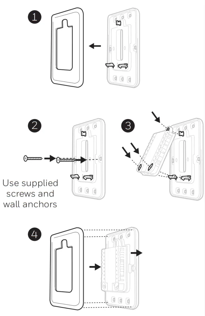
- Separate the Cover Plate from Mounting Plate.
- Mount the Mounting Plate onto the wall using any of the 8 screw holes. Insert and tighten mounting screws supplied with Cover Plate Kit. Do not overtighten. See Figure
- Make sure the Mounting Plate is level.
- Attach the UWP by hanging it on the top hook of the Mounting Plate and then snapping the bottom of the UWP in place. See Figure 3.
- Snap the Cover Plate onto the Mounting Plate. See Figure 4.
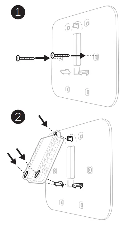
For the rectangular cover plate:
1. Mount the Cover Plate on the wall using any of the 6 screw holes. Insert and tighten the mounting screws supplied with the Cover Plate. Do not overtighten. See Figure
- Make sure the Cover Plate is level. Attach the UWP by hanging it on the top hook of the Cover Plate and then snapping the bottom of the UWP in place. See Figure 2.
- If there are no existing wall anchors:
 a. Position the Cover Plate on wall. Level and mark hole positions. See Figure 1.
b. Drill holes at marked positions, and then lightly tap supplied wall anchors into the wall using a hammer.
- If your box contains red anchors, drill 7/32″ (5.6 mm) holes.
- If your box contains yellow anchors, drill 3/16″ (4.8 mm) holes.
- Use 2x supplied screws (#8 1-1/2″ (38 mm) for red anchors and #6 1-1/2″ (38 mm) for yellow anchors).
UWP Mounting System installation
- Open the package to find the UWP.
- Position the UWP on the wall. Level and mark hole positions. See Figure 2.
Drill holes at marked positions, and then lightly tap supplied wall anchors into wall using a hammer.
If your box contains red anchors, drill 7/32″ (5.6 mm) holes for drywall.
If your box contains yellow anchors, drill 3/16″ (4.8 mm) holes for drywall. - Pull the door open and insert wires through the wiring hole of the UWP. See Figure 3.
- Place the UWP over the wall anchors. Insert and tighten mounting screws supplied with the UWP. Do not overtighten. Tighten until the UWP no longer moves. Close the door. See Figure 4.
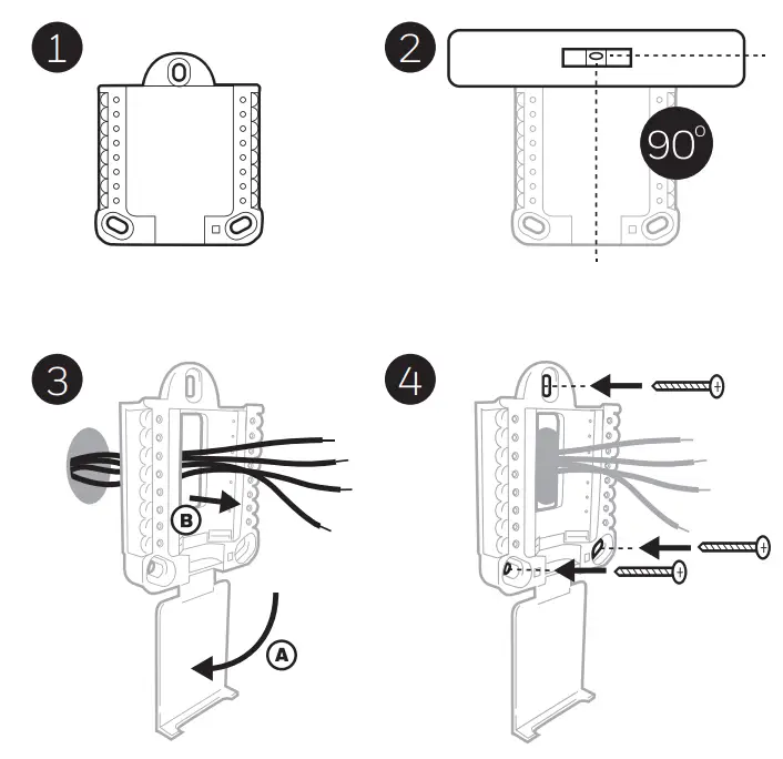
Use 3x supplied screws (#8 1-1/2″ [38 mm] for red anchors and #6 1-1/2 [38 mm] for yellow anchors)
Wiring UWP
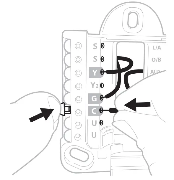
Push down on the tabs to put the wires into the inner holes of their corresponding terminals on the UWP (one wire per terminal) until they are firmly in place. Gently tug on the wires to verify they are secure. If you need to release the wires again, push down the terminal tabs on the sides of the UWP.
 This wiring is just an example, yours may vary.
Terminal designations
| Conventional Systems | Heat pump systems | ||
| Terminal | Description | Terminal | Description |
| S/S | Input for a wired indoor, outdoor sensor | S/S | Input for a wired indoor, outdoor sensor |
| Y | Compressor Stage 1 | Y | Compressor Stage 1 |
| Y2 | Compressor Stage 2 | Y2 | Compressor Stage 2 |
| G | Fan Relay | G | Fan Relay |
| C | 24VAC Common wire from the secondary side of the cooling transformer (if 2 transformers) | C | 24VAC Common wire from the secondary side of the cooling transformer |
| K* | Connect to K on the C-wire adaptor | K* | Connect to K on the C-wire adaptor |
| U/U** | Relay for ventilation | U/U** | Relay for ventilation |
| A | L/A | Connect to compressor monitor | |
| W | Heat Stage 1 | O/B | Changeover valve for heat pumps |
| W2 | Heat Stage 2 | Aux | Backup Heat |
| E | Emergency Heat | ||
| R | 24 VAC Heating transformer | R | 24 VAC Heating transformer |
| Rc | 24 VAC Cooling transformer | Rc | 24 VAC Cooling transformer |
* The THP9045A1098 C-wire adaptor is used on heat/cool systems when you only have four wires at the thermostat and you need a fifth wire for a common wire. Use the K terminal in place of the Y and G terminals on conventional or heat pump systems to provide control of the fan and the compressor through a single wire–the unused wire then becomes your common wire. See THP9045 instructions for more information.
** Ventilation is not available on all models. When the U slider is in the down position (2 wires), the U contacts are a dry set of contacts. If your ventilation system requires 24 volts, move the U slider to the up position (1 wire). The lower U terminal is internally jumped to the Rc terminal. In this application, you would hook up one wire from your damper to the upper U terminal and the other to the common side of the transformer.
Setting Slider Tabs
Set R Slider Tab, see Figure 1.
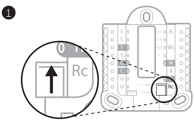
- Use a built-in jumper (R Slider Tab) to differentiate between one or two transformer systems.
- If there is only one R wire, and it is connected to the R, Rc, or RH terminal on the old thermostat, set the slider to the up position (1 wire).
- If there is one wire connected to the R terminal and one wire connected to the Rc terminal, set the slider to the down position (2 wires).
Set U Slider Tab, see Figure 2.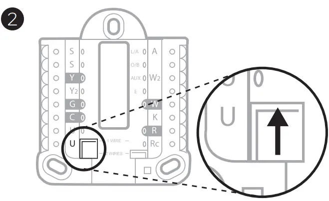
- Use a built-in jumper (U Slider Tab) of the relay to wire ventilation. Please note that ventilation is not supported on all models.
- When the U Slider Tab is in the down position (2 wires) the U contacts are a dry set of contacts.
- If the ventilator is powered by the cooling transformer, move the jumper switch to the up position (1 wire). With this switch set to 1 wire, the lower U terminal is internally jumped to the Rc terminal. In this application, hook up one wire from the vent damper to the U terminal and the other to the common side of the cooling system transformer.
Wiring
NOTES:
- Available wiring configurations differ by product models/product numbers.
- Use 18- to 22- gauge thermostat wire. A shielded cable is not required.
- Set the R Slider Tab on the UWP to the up position (1 wire) for 1 transformer system or the down position (2 wires) for 2 transformer systems. See “Setting Slider Tabs” on page 5.
- Set the U Slider Tab to the up position (1 wire) for non-powered ventilation or the down position (2 wires) for powered ventilation. See “Setting Slider Tabs” on page 5.
Conventional systems
| 1H/1C System (1 transformer) R Power Rc [R+Rc joined by Slider Tab] Y C Kompressor contactor C 24V A common W Heat the relay G Fan relay |
Hot Water Relay Panel R Power Rc [R+Rc joined by Slider Tab] W Heat Relay C 24VAC common NOTE: If the panel does not provide 24 volts of AC at R and C, set the slider to a down position and wire a separate transformer to Rc and C. |
| 1H/1C System (2 transformers) R Power (heating transformer) Rc Power (cooling transformer) Y Compressor contactor C 24 VAC common from the cooling transformer W Heat relay G Fan relay |
Heat-only System with Fan R Power Rc [R+Rc joined by Slider Tab] C 24VAC common W Heat relay G Fan relay |
| 2H/2C System (1 transformer) R Power Rc [R+Rc joined by Slider Tab] Y Compressor contactor (stage 1) C 24VAC common W Heat the relay (stage 1) G Fan relay W2 Heat the relay (stage 2) Y2 Compressor contactor (stage 2) |
Cool-only System with Fan R Power Rc [R+Rc joined by Slider Tab] Y Compressor contactor C 24VAC common G Fan relay |
| 1H/1C Heat Pump System R Power Rc [R+Rc joined by Slider Tab] Y Compressor contactor C 24VAC common O/B Changeover valve G Fan relay |
2H/2C Heat Pump System R Power Rc [R+Rc joined by Slider Tab] Y Compressor contactor (stage 1) C 24VAC common O/B Changeover valve G Fan relay Y2 Compressor contactor (stage 2) L Heat pump fault input |
| 2H/1C Heat Pump System R Power Rc [R+Rc joined by Slider Tab] Y Compressor contactor C 24VAC common O/B Changeover valve G Fan relay Aux Auxiliary heat* E Emergency heat relay* L Heat pump fault input NOTE: If dual fuel, TH6320WF2003 model needed. |
3H/2C Heat Pump System R Power Rc [R+Rc joined by Slider Tab] Y Compressor contactor (stage 1) C 24VAC common O/B Changeover valve G Fan relay Aux Auxiliary heat* E Emergency heat relay* Y2 Compressor contactor (stage 2) L Heat pump fault input NOTE: TH6320WF2003 only. |
NOTE: Do NOT use W for heat pump applications. Auxiliary heat must wire to AUX or E.
* If you do not have separate wires for the Aux and E terminals, connect the wire to the Aux terminal. 7Ventilation systems
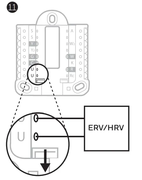
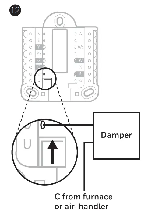
NOTE: Ventilation is not available on all models.
Using U Slider Tab
Wired to ERV/HRV whole house ventilator with internal power supply.
 Wired to fresh air damper powered by furnace transformer.
Mounting thermostat
- Push excess wire back into the wall opening.
- Close the UWP door. It should remain closed without bulging.
- Align the UWP with the thermostat, and push gently until the thermostat snaps in place.
- If needed, gently pull to remove the thermostat from the UWP.
- Search for local rebates: Your thermostat may now be eligible for local rebates. Search for offers in your area at HoneywellHome.com/Rebates
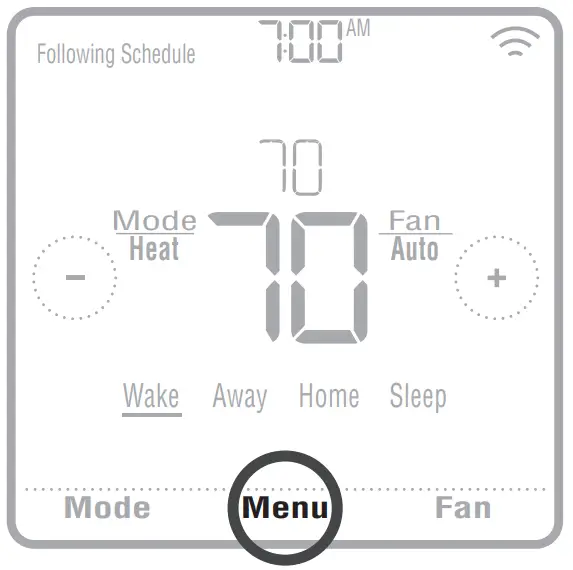
Installer setup- using the thermostat
Setup using the thermostat
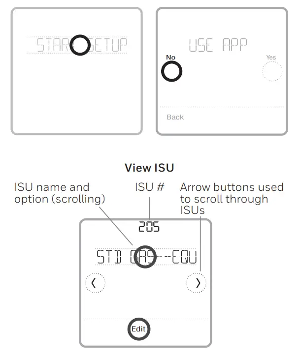
- After the thermostat has powered up, touch START SETUP on the thermostat. You’ll be asked if you want to perform setup via the app. Touch No.
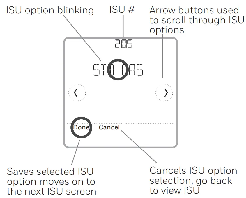
- Touch < or > toggle between Installer Set-Up (ISU) options.
- Touch Edit < or > touch the text area and then touch or edit the default setup option.
- Touch Done < or > touch the text area to confirm the setting or press Cancel.
- Touch < or > to continue to set up another ISU option.
NOTES:
- To see a list of all setup parameters, go to “Installer setup options (ISU) advanced menu” on page 12. The thermostat displays the ISU name and the ISU number.
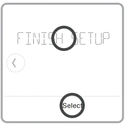
- To finish setup and save your settings, scroll to the Finish screen at the end of the ISU list.
- Touch Select or touch text area to save changes and exit, or touch to return to initial setup screen.
Installer setup using the Resideo Pro app
Setup using the app
Download the Resideo Pro or Honeywell Home app from App Store or Google Play to install and personally invite your customer to connect the installed thermostat at the same time.![]()
With the Resideo Pro app, you can personally invite your customer to connect their account.
Installer setup advanced menu
To access the advanced menu, press and hold the Menu button for 5 seconds. Touch or to go through the options in the advanced menu.
 Advanced menu options
Device Setup
This is used to access the device ISU setting.
Screen Lock
The thermostat touch screen can be set to lock fully or partially.
Rater View
A read-only place to view all the ventilation settings.
System Test
Test the heating and cooling system.
Range Stop (Temperature)
Set the minimum, maximum, cool and heat temperature set points.
Reset
Access all reset options on the thermostat.
This is the only place to access factory reset.
Key features
Note: Long press of Menu button for 5 seconds to access Advanced Menu options.
The screen will wake up by pressing the center area of the displayed temperature. The screen will stay lit for 45 seconds. Brightness can be adjusted in the Menu.
Installer setup options (ISU) advanced menu
Table 1.
Note: ISU options available may vary upon the thermostat model and equipment setup.
| # ISU | ISU Name | ISU Options (defaults in bold) | Notes |
| 120 | Schedule Type | No Schedule MO-SU = Every day the same MO-FR, SA, SU = 5-1-1 scheduleMO-FR, SA-SU = 5-2 schedule Each Day = Everyday individual | You can change the default MO-FR, and SA-SU schedule here. To edit periods during days, temperature setpoints, or to turn Schedule On/Off, from the home screen, go to MENU/SCHEDULE. |
| 125 | Temp Scale | Fahrenheit, Celsius | |
| 130 | Outdoor Temp | No, Wired, Internet | Select outdoor temperature data source. This ISU automatically defaults to the Internet when registered to the Honeywell Home app and no wired outdoor sensor is selected. We recommend using a wired outdoor sensor connected to the “S” terminals on the UWP. (See “Wiring” on page 6.) An outdoor temperature is required to set the following ISUs: ISU 355 Compressor Lockout, ISU 356 Aux Heat Lockout, ISU 1013 Low Outdoor Temperature Ventilation Lockout, ISU 1014 High Outdoor Temperature Ventilation Lockout, and ISU 1015 High Outdoor Dew Point Ventilation Lockout. |
| 200 | System Type | Conventional Forced Air Heat Pump Boiler Cool Only |
A basic selection of systems your thermostat will control. |
| 205 | Equipment Type | Conventional Forced Air Heat: Standard Gas (STD GAS), High Efficiency Gas (EFF GAS), Oil, Electric, Fan Coil* Heat Pump: Air To Air, Geothermal Boiler: Hot Water, Steam |
This option selects the equipment type your thermostat will control. Note: This option is NOT displayed if ISU 200 is set to Cool Only. *Fan coil setting is for a residential application with a hot water coil in an air-handler. |
| 218 | Reversing Valve | 0/B on Cool, 0/B on Heat | This ISU is only displayed if ISU 200 is set to Heat Pump. Select whether reversing valve O/B should energize on cool or on heat |
| 220 | Cool Stages (#200=Conv./ 200=HP) | 0, 1, 2 | Only 1 compressor stage is available on the TH6220WF model if configured for a heat pump. |
| 221 | Heat Stages/Aux/E Stages (#200=Conv./ 200=HP) | Heat Stages: 0, 1, 2
AUX/E Stages: 0, 1 |
Maximum of 2 Heat Stages for conventional systems. Maximum of 1 Aux/E stage for heat pump systems. |
| 230 | Fan Control | Equipment, Thermostat | This ISU is only displayed if ISU 205 is set to Electric Forced Air or Fan Coil. |
| 253 | Aux/E Control | Both Aux/E, Either Aux/E | Set “EITHER AUX/E” if you want to set up and control Auxiliary and Emergency heating separately. This ISU is only displayed if ISU 200 is set to Heat Pump AND if ISU 221 Aux/E stages = 1. Note: This ISU is available on the TH6320 model only. |
| # ISU | ISU Name | ISU Options (defaults in bold) | Notes |
| 255 | Aux Heat Type | Electric, Gas/Oil (or Fossil Forced Air) | This ISU is displayed only if ISU 200 is set to heat pump AND if ISU 221 Aux/E heat stages = 1. Note: Options of this ISU may vary depending on the model of the thermostat. |
| 256 | EM Heat Type | Electric, Gas/Oil (or Fossil Forced Air) | This ISU is displayed only if ISU 200 is set to Heat Pump AND if ISU 221 Aux/E heat stages = 1 AND if ISU 253 is set to run AUX/E heat separately.
Note: This ISU may not be available at all on some models. |
| 260 | Fossil Kit Control | Thermostat, External (Fossil Fuel Kit Controls Backup Heat) | This ISU is displayed only if ISU 200 is set to Heat Pump AND if ISU 221 Aux/E heat stages = 1, AND if ISU 256 is set to Gas/Oil. Note: This ISU is available on the TH6320 model only. |
| 300 | Auto Changeover | On, Off | OFF: The user must select heating or cooling as needed to maintain the desired indoor temperature. ON (Automatic): On (enabled) Allows the user to select Auto Changeover as one of the system modes from the home screen. In auto mode, the thermostat can control either heating or cooling to maintain the desired indoor temperature. |
| 303 | Auto Differential | 0 °F to 5 °F or 0.0 °C to 2.5 °C | The differential is the minimum number of degrees rise or fall required during off-cycle to switch from the last active mode (heat or cool) to the opposite mode when the thermostat is in auto-changeover. The differential is NOT deadband. The deadband temperature between when heating (or cooling) cycles on and cycles off to maintain the setpoint is not adjustable. The thermostat uses an algorithm that fixes Deadband at 0 °F (0 ° C). |
| 305 | High Cool Stage Finish | Yes, No | This ISU is only displayed when the thermostat is set to 2 cool stages. When set to YES, this feature keeps the higher stage of the cooling equipment running until the desired setpoint is reached. |
| 306 | High Heat Stage Finish | Yes, No | This ISU is only displayed when the thermostat is set to 2 or more heat stages. When set to YES, this feature keeps the higher stage of the heating equipment running until the desired setpoint is reached. |
| 340 | Aux Heat Droop | 0 = Comfort; 2 °F to 15 °F from setpoint (in 1 °F incre- ments) or 1.0 °C to 7.5 °C from setpoint (in 0.5 °C increments) | Aux heat droop can be set on heat pump systems with an auxiliary heat stage. The Comfort setting is NOT available for Dual Fuel systems. Default setting is 0 °F (0 ° C) (Comfort) for Electric while 2 °F (1.0 °C) for Gas/ Oil. The indoor temperature must drop to the selected droop setting before the thermostat will turn Aux Heat on. For example, if Aux Heat is set to 2 °F (1.0 °C), the indoor temperature must be 2 ° F (1.0 ° C) away from the setpoint before Aux Heat turns on. When set to Comfort, the thermostat will use Aux Heat as needed to keep the indoor temperature within 1 °F (0.5 ° C) degree of the setpoint. |
| 350 | Up Stage Timer Aux Heat | Off, 30, 45, 60, 75, 90 minutes 2, 3, 4, 5, 6, 8, 10, 12, 14, 16 hours |
The Auxiliary Heat Upstage Timer starts when the highest stage of the previous heating equipment type turns on. Auxiliary heat will be used (if needed) when the timer expires. This ISU is only displayed when ISU 340 (AUX Heat Droop) is set to 2 °F (1.0 °C) or higher. |
| # ISU | ISU Name | ISU Options (defaults in bold) | Notes |
| 355 | Balance Point (Compressor Lockout) | Off, 5 °F to 60 °F (in 5 °F increments) or
-15.0 °C to 15.5 °C (in 2.5 °C or 3.0 °C increments) |
Compressor Lockout requires an outdoor temperature. Set Compressor Lockout to the temperature below which it is inefficient to run the heat pump. When the outside temperature is below this setting, the thermostat will lock out the heat pump and run Aux Heat only. This ISU is only displayed if ISU 130 = Wired or Internet, ISU 200 is set to Heat Pump, ISU 221 Aux/E stages = 1, AND ISU 260 is set to Thermostat. We recommend using a wired remote sensor as an outdoor temperature source. Default is 40 °F (4.4 °C) if ISU 205 Heating Equipment is Air to Air Heat Pump and ISU 255 Aux Heat Type is Gas/Oil. Default is Off if ISU 205 Heating Equipment is Air to Air Heat Pump and ISU 255 Aux Heat Type is Electric. Default is Off if ISU 205 Heating Equipment is Geothermal. Compressor Lockout is optional for any type of heat pump (Air to Air Heat Pump, Geothermal Heat Pump). |
| 356 | Aux Heat Lock Out (Aux Heat Outdoor Lockout) | Off, 5 °F to 65 °F (in 5 °F increments) or
-15.0 °C to 18.5 °C (in 2.5 °C or 3.0 °C increments) |
Aux Heat Lockout requires an outdoor temperature. Set Aux Heat Lockout to optimize energy bills and not allow it to run the more expensive Aux Heat source above a certain outdoor temperature limit. This ISU is only displayed if ISU 200 is set to Heat Pump, AND ISU 260 is set to Thermostat control, AND if ISU 221 Aux/E stages = 1. |
| 365 | Cool 1 CPH (Cooling cycle rate stage 1) | 1 – 6 CPH (3 CPS) | This ISU is only displayed when Cool /Compressor Stages is set to 1 or more stages. Cycle rate limits the maximum number of times the system can cycle in a 1 hour period measured at a 50% load. For example, when set to 3 CPH, at a 50% load, the most the system will cycle is 3 times per hour (10 minutes on, 10 minutes off). The system cycles less often when load conditions are less than or greater than a 50% load. |
| 366 | Cool 2 CPH (Cooling cycle rate stage 2) | 1 – 6 CPH (3 CPS) | This ISU is only displayed when Cool /Compressor Stages is set to 2. |
| 370 | Heat 1 CPH (Heating cycle rate stage 1) | 1 – 12 CPH | This ISU is only displayed when Heat Stages is set to 1 stage or more stages. Cycle rate limits the maximum number of times the system can cycle in a 1 hour period measured at a 50% load. For example, when set to 3 CPH, at a 50% load, the most the system will cycle is 3 times per hour (10 minutes on, 10 minutes off). The system cycles less often when load conditions are less than or greater than a 50% load. The recommended (default) cycle rate settings are below for each heating equipment type: Standard Efficiency Gas Forced Air = 5 CPH; High Efficiency Gas Forced Air =3 CPH; Oil Forced Air = 5 CPH; Electric Forced Air = 9 CPH; Fan Coil = 3 CPH; Hot Water Radiant Heat = 3 CPH; Steam = 1 CPH. |
| 371 | Heat 2 CPH (Heating cycle rate stage 2) | 1 – 12 CPH | This ISU is only displayed when Heat Stages is set to 2 stages. The recommended (default) cycle rate settings are below for each heating equipment type: Standard Efficiency Gas Forced Air = 5 CPH; High Efficiency Gas Forced Air = 3 CPH; Oil Forced Air = 5 CPH; Electric Forced Air = 9 CPH; Fan Coil = 3 CPH; Hot Water Radiant Heat = 3 CPH; Steam = 1 CPH. |
| 375 | Aux Heat CPH (Heating cycle rate Auxiliary Heat) | 1 – 12 CPH | This ISU is only displayed when ISU 200 = Heat Pump and ISU 221=1. It is only displayed when Auxiliary Heat is configured. The recommended cycle rate settings are below for each heating equipment type: Standard Efficiency Gas Forced Air = 5 CPH; High Efficiency Gas Forced Air = 3 CPH; Oil Forced Air = 5 CPH; Electric Forced Air = 9 CPH. |
| # ISU | ISU Name | ISU Options (defaults in bold) | Notes |
| 378 | EM Heat CPH (Heating cycle rate Emergency Heat) | 1 – 12 CPH | This ISU is only displayed when Emergency Heat is configured and ISU 253: Aux/E Terminal Control is set to control Aux and E heat Independently. The recommended cycle rate settings are below for each heating equipment type: Standard Efficiency Gas Forced Air = 5 CPH; High Efficiency Gas Forced Air = 3 CPH; Oil Forced Air = 5 CPH; Electric Forced Air = 9 CPH. |
| 387 | Compressor Protection | Off, 1 – 5 minutes | The thermostat has built-in compressor protection (minimum off timer) that prevents the compressor from restarting too early after a shutdown. The minimum-off timer is activated after the compressor turns off. If there is a call during the minimum-off timer, the thermostat shows “Wait” in the display. This ISU is displayed if ISU 220 is set to at least 1 stage. |
| 390 | Ext Fan Run Time in Cool | Off, 30, 60, 90 seconds2, 3, 4, 5, 6, 7, 8, 9, 10, 11, 12, 13, 14, 15 minutes | After the call for cooling ends, the thermostat keeps the fan on for the selected amount of time for increased efficiency. This may reintroduce humidity into the living space. This ISU is displayed if ISU 220 is set to at least 1 stage. |
| 391 | Ext Fan Run Time in Heat | Off, 30, 60, 90 seconds
2, 3, 4, 5, 6, 7, 8, 9, 10, 11, 12, 13, 14, 15 minutes |
After the call for heating ends, the thermostat keeps the fan on for the selected amount of time for increased efficiency. This ISU is displayed if ISU 230 is set to Thermostat Controls Fan. |
| 425 | Adaptive Recovery | On, Off | Adaptive Intelligent Recovery (AIR) is a comfortable setting. Heating or cooling equipment will turn on earlier, ensuring the indoor temperature will match the setpoint at the scheduled time. |
| 429 | Max Cool Temperature | from Min. Cool Temp. to 99 °F or to 37.0 °C (90 °F or 32 °C) | The user cannot set the cooling temperature above this level. |
| 430 | Min Cool Temperature | from 50 °F or 10.0 °C to Max. Cool Temp. (50 °F or 10 °C) | The user cannot set the cooling temperature below this level. |
| 431 | Max Heat Temperature | from Min. Heat Temp. to 90 °F or to 32.0 °C (90 °F or 32 °C) | The user cannot set the heating temperature above this level. |
| 432 | Min Heat Temperature | from 40 °F or 4.4 °C to Max. Heat Temp. (50 °F or 10 °C) | The user cannot set the heating temperature below this level. |
| 500 | Indoor Sensor | Yes, No | Set this ISU when you want to wire a remote indoor sensor to the “S” terminals on the UWP – see “Wiring” on page 6. This ISU is only displayed only if ISU 130 is set to NO wired outdoor sensor configured |
| 515 | Sensor type | 10k, 20k | Choose the resistance type of wired indoor sensor. This ISU is only displayed when the indoor sensor is configured – ISU 500. |
| 520 | Temperature Control | Thermostat, Wired, Average | This ISU is only displayed when the indoor sensor is configured – ISU 500. You can choose what temperature source to be used or you can ask the thermostat to use both thermostat and remote sensors for higher accuracy of measurement. |
| 702 | Air Filters | 0 – 2 | This ISU refers to the number of air filters in the system. |
| 711 | Air Filter 1 Reminder | Off10, 20, 30, 45, 60, 90, 120, 150 Run Time Days30, 45, 60, 75 Days 3, 4, 5, 6, 9, 12, 15 Months | Choose either calendar or equipment run time-based reminder. |
| 712 | Air Filter 2 Reminder | Off 10, 20, 30, 45, 60, 90, 120, 150 Run Time Days 30, 45, 60, 75 Days 3, 4, 5, 6, 9, 12, 15 Months | Choose either calendar or equipment run time-based reminder. |
| # ISU | ISU Name | ISU Options (defaults in bold) | Notes |
| 810 | Hum Pad Reminder | Off6, 12 Calendar Months | |
| 921 | Deum Filter Reminder | Off 30, 60 Calendar Days 3 – 12 Calendar Months (in 1-month increments) | |
| 1000 | Vent Type | None, ERV/HRV, Passive, Fresh Air Damper | Note: The thermostat does not control ventilation. ERV/HRV: The thermostat controls an Energy Recovery Ventilator or Heat Recovery Ventilator for ventilation. Passive (Fan Only): The thermostat turns on the fan for ventilation. When set to the passive fan, the thermo- stat does not control a damper or ventilator. The passive ventilation/passive fan setting only runs the indoor blower fan. This setting does not open a damper or run a ventilator. To use this setting for ventilation, the home would need to be set up with a pipe from outdoors into the return duct that is either permanently open or has a damper that automatically opens whenever the blower fan is on. Note: Some models only offer the passive fan setting. |
| 1005 | Vent Method | ASHRAE 2010, ASHRAE 2013, Percent On-Time | Note: Options of this ISU may vary depending on the model of the thermostat. |
| 1006 | Vent Fan Control | Thermostat, Equipment | Thermostat: The thermostat turns on the ventilation and the fan when ventilation is needed. Equipment: Ventilation equipment controls the blower fan. |
| 1007 | Bedrooms | 1 – 6 (2) | This ISU is only displayed when ISU 1005 Ventilation Method is set to ASHRAE 2010 or 2013. |
| 1008 | Home Size | 1000 sq. Ft. – 5000 Sq. Ft. (1000 sq. Ft.) | This ISU is only displayed when ISU 1005 Ventilation Method is set to ASHRAE 2010 or 2013. |
| 1009 | Vent Rate | 30CFM – 350CFM (in 5CFM increments) (150CFM) | This ISU is only displayed when ISU 1005 Ventilation Method is set to ASHRAE 2010 or 2013. |
| 1011 | Vent Percent On-Time | 10% – 100% (30%) | The thermostat operates ventilation equipment based on a percentage entered in the installer setup (ISU 1012). For example, if Percent on Time is set to 50%, the ventilation equipment will run at random times during a 1-hour period until it reaches a 50% run time (approximately 30 minutes). This ISU is only displayed if ISU 1005 is set to Percent On Time. |
| 1012 | Vent Priority | Lockouts, ASHRAE | Lockouts are Priority: The thermostat places a priority on lockouts versus the ASHRAE ventilation standard. The thermostat will not run ventilation during the following lockout conditions (if configured), unless you manually call for ventilation: Lockout Ventilation during Outdoor Conditions (ISU 1013, 1014, and 1015). Lockout Ventilation during “Sleep” program periods. Note: This option is set by the user on the Ventilation screen in the Menu. ASHRAE is Priority: ASHRAE requires additional ventilation following a long off cycle. The thermostat meets the ASHRAE ventilation standard by running additional ventilation when outdoor conditions are favorable. If ASHRAE cannot be met when outdoor conditions are favorable, the thermostat will override the outdoor lockouts and run ventilation. When using this option, it is recommended that you increase the rate (CFM) of the ventilation equipment to meet the ASHRAE ventilation standard in a shorter run time. The ability to lockout ventilation during the “Sleep” is not an option when you select ASHRAE as a Priority. |
| # ISU | ISU Name | ISU Options (defaults in bold) | Notes |
| 1013 | Low Outdoor Temp Vent Lockout | Off, -20 °F to -40 °F (in 5 °F increments) or
-28.0 °C to -4.0 °C (in 2.0 °C increments) |
ISU 130 must be set to Wired or Internet. This ISU is only displayed when ISU 1000 Ventilation Type is set to ERV / HRV or Fresh Air Damper. |
| 1014 | High Outdoor Temp Vent Lockout | Off, 80 °F to 110 °F (in 5 °F increments) or 26 °C to 44 °C (in 2 °C increments) | ISU 130 must be set to Wired or Internet. This ISU is only displayed when ISU 1000 Ventilation Type is set to ERV / HRV or Fresh Air Damper. |
| 1015 | High Outdoor Dewpoint Vent Lockout | Off, 65 °F to 85 °F (in 5 °F increments) or 18 °C to 30 °C (in 2 °C increments) | ISU 130 must be set to Internet. This ISU is only displayed if ISU 1000 Ventilation Type is set to ERV/ HRV or Fresh Air Damper. |
| 1017 | Vent Core Reminder | Off, 3, 6, 9, 12 months | This ISU is displayed only if ISU 1000 is set to ERV/HRV. |
| 1018 | Vent Filter Reminder | Off, 3, 6, 9, 12 months | |
| 1100 | UV Devices | 0 – 2 | Some systems may have two UV devices, one for the A-Coil and another for Air Treatment. A replacement reminder can be set up for each one separately. |
| 1105 | UV Bulb 1 Reminder | Off, 6, 12, 24 months | |
| 1106 | UV Bulb 2 Reminder | Off, 6, 12, 24 months | |
| 1401 | Idle Brightness | 0= Off, 0 – 5 | Adjust the brightness of an inactive backlight (idle screen) from default 0 (backlight off) to 5 (maximum brightness). |
| 1410 | Clock Format | 12 hour, 24 hour | |
| 1415 | Daylight Saving | On, Off | Set to Off in areas that do not follow Daylight Saving Time. |
| 1420 | Temp Offset | Off, -3 °F to 3 °F (in 1 °F increment) or -1.5 °C to 1.5 °C (in 0.5 °C increments) | 0 °F (0 °C) – No difference in displayed temperature and the actual room temperature. The thermostat can display up to 3 °F (1.5 C) lower or higher than the actual measured temperature. |
Performing a system test
You can test the system setup in ADVANCED MENU under the SYSTEM TEST option.
- Press and hold Menu on the thermostat for 5 seconds to access ADVANCED MENU options.
- Touch or go to SYSTEM TEST.
- Touch Select or touch text area.
- Touch or select system test type. Touch Select or touch text area.
- For the heat test and cool test, use or to activate each stage of the equipment. For the fan test, use or to turn the fan on and off.
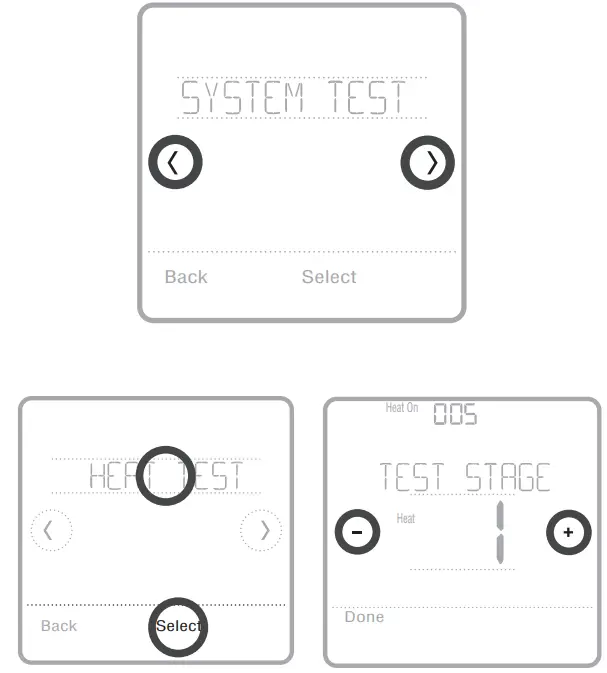
NOTE: The clock is used as a timer while the stages are running. The Heat On and Cool On indicators are displayed when the system test is running.
Viewing equipment status
You can see the status of thermostat-controlled equipment in the Menu under the EQMT STATUS option.
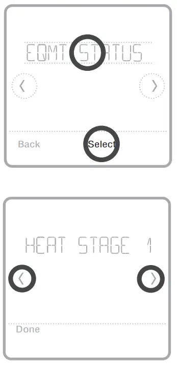
- Touch Menu on your thermostat.
- Touch or go to EQMT STATUS. Touch Select or touch text area.
- Touch or view the statuses of all the equipment the thermostat is controlling. Depending on what features the thermostat supports or how it was installed, the Equipment Status screen reports data for the following systems:
- Heating and cooling
- Fan
- Ventilation (available on certain models only)
Troubleshooting
| Screen is blank | • Check the circuit breaker and reset if necessary. • Make sure the power switch at the heating and cooling system is on. • Make sure the furnace door is closed securely. |
| The screen is difficult to read | • Change screen brightness in the thermostat Menu. Increase brightness intensity for the inactive backlight of the thermostat screen (max. is level 5). |
| The heating or cooling system does not respond | • Touch Mode to set the system to Heat. Make sure the temperature is set higher than the Inside temperature. • Touch Mode to set the system to Cool. Make sure the temperature is set lower than the Inside temperature. • Check the circuit breaker and reset if necessary. • Make sure the power switch at the heating & cooling system is on. • Make sure the furnace door is closed securely. |
| Heat runs with cooling | • Verify there is not a wire attached to W for heat pump systems. See wiring on pages 6-7. |
Alerts and reminders
Alerts and reminders are displayed via the alert symbol and alert number in the clock area on the home screen. You can read more information about active alerts, snooze or dismiss non-critical alerts in Menu/Alerts.
| Number | Alert/Reminder | Definition |
| 164 | Heat Pump Needs Service | The heat pump needs service. Contact dealer to diagnose and service the heat pump. |
| 168 | Wi-Fi Radio Error | Wireless features are not available. Try removing the thermostat from the wallplate or power cycle at the breaker for 1 minute. If the code is still shown, please contact the dealer to replace the thermostat. |
| 170 | Internal Memory Error | The memory of the thermostat has encountered an error. Please contact the dealer for assistance. |
| 171 | Set the Date and Time | Set the date and time on your thermostat. The date and time are required for certain features to operate, like the program schedule. |
| 173 | Thermostat Temperature Sensor Error | The sensor of the thermostat has encountered an error. Please contact the dealer to replace the Thermostat. |
| 175 | AC Power Resumed | AC power resumed to thermostat after power loss. |
| 177 | Indoor Temperature Sensor Error | The wired indoor temperature sensor is not connected or there is a wiring short. Please contact the dealer for assistance. |
| 178 | Outdoor Temperature Sensor Error | The wired outdoor temperature sensor is not connected or there is a wiring short. Please contact the dealer for assistance. |
| Number | Alert/Reminder | Definition |
| 181 | Replace Air Filter (1) | Replace air filter (1). Reset the timer by touching the “dismiss” button on the thermostat screen after it is replaced. |
| 182 | Replace Air Filter (2) | Replace air filter (2). Reset the timer by touching the “dismiss” button on the thermostat screen after it is replaced. |
| 183 | Clean Humidifier Tank and Replace Water Filter | Clean the humidifier tank and replace the water filter or contact the dealer to do this for you. Reset the timer by touching the “dismiss” button on the thermostat screen after it is replaced. |
| 184 | Replace Humidifier Pad | Replace the humidifier pad. Reset the timer by touching the “dismiss” button on the thermostat screen after it is replaced. |
| 185 | Replace Dehumidifier Filter | Replace the dehumidifier filter. Reset the timer by touching the “dismiss” button on the thermostat screen after it is replaced. |
| 186 | Clean Ventilator Core | Clean ventilator core. Reset the timer by touching the “dismiss” button on the thermostat screen after it is replaced. |
| 187 | Clean or Replace Ventilator Filter | Clean or replace the ventilator filter. Reset the timer by touching the “dismiss” button on the thermostat screen after it is replaced. |
| 188 | Replace UV Bulb (1) | Replace UV Bulb (1). Reset the timer by touching the “dismiss” button on the thermostat screen after it is replaced. |
| 189 | Replace UV Bulb (2) | Replace UV Bulb (2). Reset the timer by touching the “dismiss” button on the thermostat screen after it is replaced. |
| 210 | Register Online For Outdoor Temperature | Online registration is required to receive outdoor temperature from the Internet. Outdoor temperature is needed for your current system setup. Download the Honeywell Home app to register your thermostat. |
| 388 | Register Online for Remote Access and Outdoor Temperature | Online registration is required for remote access and outdoor temperature. Download the Honeywell Home app to register your thermostat. |
| 399 | No Internet | The connection to the Internet has been lost. Please check your network settings. |
| 400 | No Wi-Fi Signal | The Wi-Fi signal has been lost. Please wait for the thermostat to reconnect or select a new Wi-Fi network. Follow steps in the Honeywell Home app |
| 508 | Wi-Fi Not Configured | Please download the Honeywell Home app and follow the steps to connect the thermostat to your Wi-Fi network. |
Specifications
Temperature Ranges
Heat: 40 °F to 90 °F (4.5 °C to 32.0 °C)
Cool: 50 °F to 99 °F (10.0 °C to 37.0 °C)
Operating Ambient Temperature 37 °F to 102 °F (2.8 °C to 38.9 °C)
Shipping Temperature –20 °F to 120 °F (-28.9 °C to 48.9 °C)
Operating Relative Humidity
5% to 90% (non-condensing)
Physical Dimensions in inches (mm) (H x W x D)
T6 Pro Smart Thermostat (TH6320WF2003):
4-5/64 x 4-5/64 x 1-1/16 (104 x 104 x 27)
T6 Pro Smart Thermostat (TH6220WF2006): 4-5/64 x 4-5/64 x 1-1/16 (104 x 104 x 27
Electrical Ratings
| Terminal | Voltage (50Hz/60Hz) | Running Current |
| W Heating | 20 Vac-30 Vac | 0.02 A-1.0 A |
| (Powerpile) | 750 mV DC | 100 mA DC |
| W2 (Aux) Heating | 20 Vac-30 Vac | 0.02 A-1.0 A |
| E Emergency Heat | 20 Vac-30 Vac | 0.02 A-0.5 A |
| Y Compressor Stage 1 | 20 Vac-30 Vac | 0.02 A-1.0 A |
| Y2 Compressor Stage 2 | 20 Vac-30 Vac | 0.02 A-1.0 A |
| G Fan | 20 Vac-30 Vac | 0.02 A-0.5 A |
| O/B Changeover | 20 Vac-30 Vac | 0.02 A-0.5 A |
| L/A Input | 20 Vac-30 Vac | 0.02 A-0.5 A |
| U | 20 Vac-30 Vac | 0.02 A-0.5 A |
Power Consumption
Backlight On: 1.48VA
Backlight Off: 0.88VA
5-year limited warranty
For Warranty, information go to http://customer.resideo.com
Regulatory information
FCC REGULATIONS
47 CFR § 15.19 (a)(3)
This device complies with part 15 of the FCC Rules. Operation is subject to the following two conditions: 1. This device may not cause harmful interference, and 2. This device must accept any interference received, including interference that may cause undesired operation.
47 CFR § 15.21 (the USA only)
Changes or modifications not expressly approved by the party responsible for compliance could void the user’s authority to operate the equipment.
47 CFR § 15.105 (b)
See https://customer.resideo.com/en-US/support/residential/codes-and-standards/FCC15105/Pages/default.aspx for additional FCC information for this product.
IC REGULATIONS
RSS-GEN
This device contains license-exempt transmitter(s)/ receiver(s) that comply with Innovation, Science, and Economic Development Canada’s license-exempt RSS(s). Operation is subject to the following two conditions: 1. This device may not cause interference. 2. This device must accept any interference, including interference that may cause undesired operation of the device.
The operation of this equipment is subject to the following two conditions: (1) this equipment or device may not cause harmful interference, and (2) this equipment or device must accept any interference, including interference that may cause undesired operation.
CAUTION: ELECTRICAL HAZARD
Can cause electrical shock or equipment damage. Disconnect power before beginning installation.
CAUTION: EQUIPMENT DAMAGE HAZARD
Compressor protection is bypassed during testing. To prevent equipment damage, avoid cycling the compressor quickly.
CAUTION: MERCURY NOTICE
If this product is replacing a control that contains mercury in a sealed tube, do not place the old control in the trash. Contact your local waste management authority for instructions regarding recycling and proper disposal.
CAUTION: ELECTRONIC WASTE NOTICE
The product should not be disposed of with other household waste. Check for the nearest authorized collection centers or authorized recyclers. The correct disposal of end-of-life equipment will help prevent negative consequences for the environment and human health.
 Resideo Technologies, Inc
- 1985 Douglas Drive North, Golden Valley, MN 55422
- 1-800-633-3991 33-00392EFS–01
- M.S. Rev. 03-21
- Printed in the United States
- Wi-Fi® is a registered trademark of Wi-Fi Alliance®
© 2021 Resideo Technologies, Inc.
All rights reserved.
The Honeywell Home trademark is used under license from Honeywell International, Inc.
This product is manufactured by Resideo Technologies, Inc. and its affiliates.
DOWNLOAD RESOURCES
- Honeywell Home TH6220WF2006 PRO T6 Smart Programmable Thermostat [pdf] Installation Guide TH6220WF2006 PRO T6 Smart Programmable Thermostat, PRO T6 Smart Programmable Thermostat, TH6320WF2003
- Read more: https://manuals.plus/honeywell-home/th6220wf2006-pro-t6-smart-programmable-thermostat-manual#ixzz7dbTDkwaS
FAQ’S
Does the Honeywell T6 Pro have Wi-Fi?
When connected to your existing WiFi, your T6 Pro Smart Thermostat can integrate with smart home Apple HomeKit and Amazon Echo, letting you adjust your temperatures as easy as you change songs on your playlist. This WiFi thermostat also works with your heating system’s stages, up to 2 Heat/1 Cool with heat pump.
Does Honeywell T6 Pro require C wire?
The T5/T6 pro Wi-Fi thermostats do require a common wire, also known as a “C” wire. The “C” or common wire allows the thermostat to power itself, instead of using batteries. It must be connected to the C or common terminal on the furnace control board.
What is the difference between a T4 and T6 thermostat?
The main difference between the two thermostats is that T6 is a smart thermostat that can be controlled remotely through the Honeywell Home app and also has a geolocation based schedule. The T4 is a non-connected programmable thermostat that can be programmed and controlled only from the unit itself.
Can I control my Honeywell thermostat from my phone?
The Honeywell Home App
Honeywell Home is compatible with the latest OS versions of iOS and Android. We suggest always checking the applicable app store (i.e. Google Play, Apple App Store) for compatibility using the device that you will install the app on.
Can I use the T6 Pro with a heat pump?
Yes. The T6 Pro is compatible with most heating, cooling and heat pump systems.
Can I use the T6 Pro with an electric baseboard heat?
No. The T6 Pro is not compatible with electric baseboard heat (120V-240V).
Can I use the T6 Pro with a fan coil system?
Yes. The T6 Pro is compatible with most heating, cooling and heat pump systems.
What color is the C-Wire?
Blue wires are also called “C” wires because they are the Common wire. C wires are necessary for any “smart” thermostat that needs to be connected to a power source 24/7, regardless of your heat pump type.
How do I reset my Honeywell thermostat without reset button?
Resetting a Honeywell Thermostat
Power off the thermostat and remove the batteries.
Put the batteries in the wrong way, with negative to positive and positive to negative.
Wait ten seconds and put them back in the correct way.
Your thermostat will be reset to factory settings.
Will low batteries affect thermostat?
When low batteries eventually die, you’ll see a black display screen, the thermostat will stop working and your heating or cooling units won’t function. The heating and cooling system cannot respond to nonexistent temperature commands.
What happens if you wire a thermostat wrong?
Potential consequences of improper installation could include: Electric shock. Blowing a circuit breaker. Damaging the thermostat unit, the electrical system or even the AC/furnace unit itself.
Does Honeywell thermostat automatically switch heat and cool?
There are programmable thermostats that automatically switch from heat to a/c and to heat again. Some Honeywell thermostats, such as the 8000 Series, have ‘auto’ setting where you can program the Heat temperature and the cool temperature and the thermostat will automatically switch from heat to cool.
VIDEO
Honeywell Home TH6220WF2006 PRO T6 Smart Programmable Thermostat
www://honeywellhome.com/