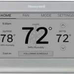
Honeywell Home TH6320WF1005 FocusPro WiFi TH6000 Series Programmable Thermostat

This manual covers the following models
TH6320WF1005: For up to 3 Heat/2 Cool systems
System Types
- Gas, oil, or electric heat with air conditioning
- Warm air, hot water, high-efficiency furnaces, heat pumps, steam, gravity
- Heat only with fan
- Cool only
Must be installed by a trained, experienced technician
Read these instructions carefully. Failure to follow these instructions can damage the product or cause a hazardous condition.
Need Help?
For assistance with this product please visit http://customer.resideo.com or call Customer Care toll-free at 1-800-468-1502
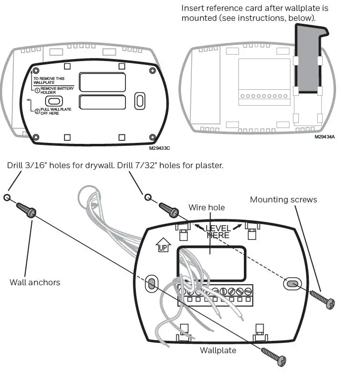
Wallplate installation
- Separate wallplate from thermostat.
- Mount wallplate as shown below.
CAUTION: ELECTRICAL HAZARD
Can cause electrical shock or equipment damage. Disconnect power before beginning installation.
Wiring
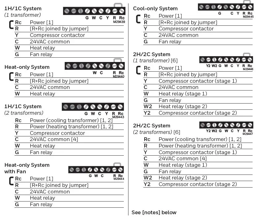
Wiring guide — conventional systems
Wire specifications:
Use 18- to 22-gauge thermostat wire. Shielded cable is not required.
- Power supply. Provide disconnect means and overload protection as required.
- Remove jumper for 2-transformer systems.
- Common connection must come from cool-ing transformer.
- In Installer Setup, set system type to Heat Only.
- In Installer Setup, set system type to 2Heat/2Cool Conventional.
- In Installer Setup, set changeover valve to O or B.
- In Installer Setup, set system type to 2Heat/1Cool Heat Pump.
- In Installer Setup, set system type to 2Heat/2Cool Heat Pump.
- In Installer Setup, set system type to 3Heat/2Cool Heat Pump.
Wiring guide — heat pump systems
Wire specifications:
Use 18- to 22-gauge thermostat wire. Shielded cable is not required.
- Power supply. Provide disconnect means and overload protection as required.
- Remove jumper for 2-transformer systems.
- Common connection must come from cool-ing transformer.
- In Installer Setup, set system type to Heat Only.
- In Installer Setup, set system type to 2Heat/2Cool Conventional.
- In Installer Setup, set changeover valve to O or B.
- In Installer Setup, set system type to 2Heat/1Cool Heat Pump.
- In Installer Setup, set system type to 2Heat/2Cool Heat Pump.
- In Installer Setup, set system type to 3Heat/2Cool Heat Pump.

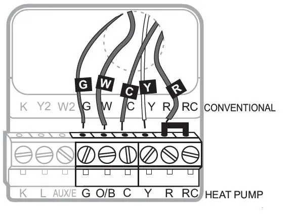
Terminal Designations
Conventional Terminal Letters:
- Y2 2nd stage compressor contactor.
- W2 2nd stage heat relay.
- K Optional wirer save module.
- Rc Cooling power. Connect to secondary side of cooling system transformer.
- R Heating power. Connect to secondary side of heating system transformer.
- W 1st stage heat relay.
- Y 1st stage compressor contactor.
- G Fan relay.
- C Common wire from secondary side of cooling transformer (if 2 transformers).
Heat Pump Terminal Letters:
- Y2 2nd stage compressor contactor. Aux/E Auxiliary/Emergency heat relay.
- K Optional wirer save module.
- Rc Cooling power. Connect to secondary side of cooling system transformer.
- R Heating power. Connect to secondary side of heating system transformer.
- O/B Changeover valve for heat pumps.
- Y 1st stage compressor contactor.
- G Fan relay.
- C Common wire from secondary side of cooling system transformer.
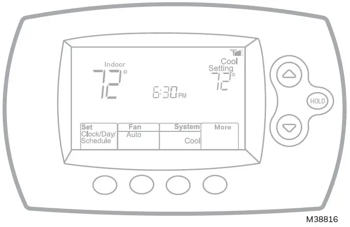
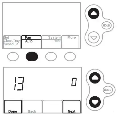
Installer setup
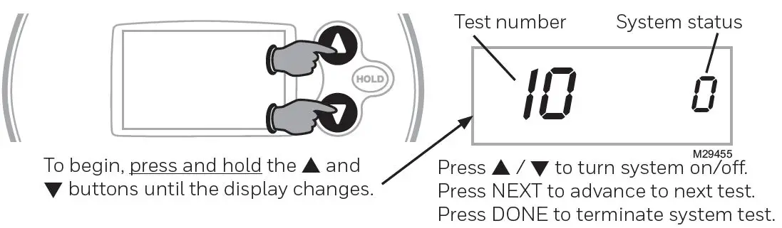
- Press Fan and s simultaneously and hold for approximately 3 seconds. The screen will change to display two numbers and the button designations will be Done, Back, blank, Next.
- Press Next until you see the function number—the larger number on the left—you want to set
- Change options for any function by pressing s or t until the correct option (smaller number on right) is displayed.
- Repeat Steps 2 and 3 until you have set all functions that you wish to change.
- When you have made all changes, press Done to save and exit
| 1 | Select System | 0 | Heat/cool: Gas, oil or electric heating with central air conditioning. |
| Type | 1
2 |
Heat pump: Heat pump without backup or auxiliary heat.
Heat only: Gas, oil or hot water heat without central air conditioning. |
|
| 3 | Heat only with fan: Gas, oil or electric heat without central air | ||
| conditioning. | |||
| 4 | Cool only: Central air conditioning only. | ||
| 5 | Heat pump: Heat pump with backup or auxiliary heating. | ||
| 6 | Heat/Cool Multiple stages: 2 heat stages, 2 cooling stages. | ||
| 7 | Heat/Cool Multiple stages: 2 heat stages, 1 cooling stage. | ||
| 8 | Heat/Cool Multiple stages: 1 heat stage, 2 cooling stages. | ||
| 9 | Heat Pump Multiple Stages: 2 heat stages, 2 cool stages. | ||
| 10 | Heat Pump Multiple Stages: 3 heat stages, 2 cool stages. | ||
| 2 | Heat Pump | 0
1 |
Cooling changeover valve: Use this setting if you connected a wire labeled “O” to the O/B terminal.
Heating changeover valve: Use this setting if you connected a wire labeled “B” to the O/B terminal. |
| Changeover Valve | |||
| (for heat pumps | |||
| only) | |||
| 3 | Heating Fan Control | 0
1 |
Gas or oil heat: Use this setting if you have a gas or oil heating system (system controls fan operation).
Electric heat: Use this setting if you have an electric heating system (thermostat controls fan operation). |
| 5 | Heating Cycle Rate | 5 Gas or oil furnace: Standard gas/oil furnace (less than 90% efficiency).
9 Electric furnace: Electric heating systems. 3 Hot water or high-efficiency furnace: Hot water system or gas furnace (more than 90% efficiency). 1 Gas/oil steam or gravity system: Steam or gravity heat systems. [Other options: 2,4,6,7,8,10,11,12] |
|
| 6 | Heating Cycle Rate Stage 2 | ||
| 7 | Heating Cycle Rate Auxiliary | ||
| 9 | 1st stage compres- sor cycle rate | 3 | Recommended for most compressors [Other options: 1, 2, 4, 5 or 6 CPH] |
| 10 | 2nd stage com- pressor cycle rate | ||
| 12 | Manual/Auto Changeover | 0
1 |
Manual changeover (Heat/Cool/Off).
Automatic changeover (Heat/Cool/Auto/Off). Automatically turns on Heat or Cool based on room temperature. Note: System maintains minimum 3°F difference between heat and cool settings. |
System setup
| 13 Adaptive Intelligent Recovery (AIR) | 1
0 |
On Off | ||||
| 14 | Temperature Format (°F/°C) | 0
1 |
Fahrenheit Celsius | |||
| 15 | Compressor protection | 5 5 minute compressor off time
[Other options: 0, 1, 2, 3 or 4-minute off time] |
||||
| 16 | Schedule Options | 1 Program schedule is on (7-day programmable).
0 Program schedule is off. Thermostat can not be programmed. |
||||
| 26 | Auxiliary Control | 0
1 |
Comfort Economy | |||
| 27 | Heat temperature range stop | 90 Max. heat temperature setting is 90°F (32°C) [Other options: 40-89°F (4°C to 32°C)] | ||||
| 28 | Cool temperature range stop | 50 Min. cool temperature setting is 50°F (10°C) [Other options: 51-99°F (11°C to 37°C)] | ||||
| 32 | Temperature display offset | 0 Thermostat displays actual room temperature
[Other options: -3, -2, -1, 1, 2, 3°F offset (-1.5°C to 1.5°C)] |
||||
| 36 | Device Name | 52 = Thermostat | ||||
| This name will identify the thermostat when you view it remotely.
If you register multiple thermostats, give each one a different name. |
1 Basement
2 Bathroom 3 Bathroom 1 4 Bathroom 2 5 Bathroom 3 6 Bedroom 7 Bedroom 1 8 Bedroom 2 9 Bedroom 3 10 Bedroom 4 11 Boat House 12 Bonus Room 13 Computer Room 14 Den 15 Dining Room |
16 Exercise Room
17 Family Room 18 Fireplace 19 Foyer 20 Game Room 21 Garage 22 Great Room 23 Guest Room 24 Gym 25 Kid’s Room 26 Kitchen 27 Kitchen 1 28 Kitchen 2 29 Laundry Room |
30 Library
31 Living Room 32 Lower Level 33 Master Bath 34 Master Bed 35 Media Room 36 Music Room 37 Nursery 38 Office 39 Office 1 40 Office 2 41 Pantry 42 Play Room 43 Pool Room |
44 Porch
45 Rec Room 46 Sewing Room 47 Spa 48 Storage Room 49 Studio 50 Sun Room 51 Theater 52 Thermostat 53 Upper Level 54 Utility Room 55 Walk In Closet 56 Wine Cellar 57 Workshop |
||
| 38 | Wi-Fi On/Off | 1 Wi-Fi is on and can be connected to a Wi-Fi network.
0 Wi-Fi is off. Thermostat cannot be connected to a Wi-Fi network. If you are not connecting the thermostat to a Wi-Fi network this will remove the text Wi-Fi Setup from the messaging center. |
||||
| 39 | Wi-Fi Connection | 1 Connected to Wi-Fi network. This is set automatically when the thermostat is connected to the Wi-Fi network.
0 Set to 0 to disconnect from the Wi-Fi network. |
||||
| 42 | Show period and day of week | 0 Period and day are not shown on the home screen.
1 Period and day are shown on the home screen. |
||||
| 85 | Restore Schedule Defaults | 0 Continue using programmed schedule.
1 Restore thermostat program to energy saving settings |
||||
| 90 | Restore Original Settings | 0 No
1 Disconnects thermostat from Wi-Fi and restores original settings (erases customizations). |
||||
Installer system test
| 10 | Heating system | 0 | Heat and fan turn off. |
| 1 | Stage 1 heat turns on. Fan turns on if Setup Function 1 is set to 1, | ||
| 5, 9 or 10 OR Setup Function 3 is set to 1 **See page 6 | |||
| 2 | Stage 2 heat turns on | ||
| 3 | Stage 3 heat turns on | ||
| 20 | Emergency heating | 0 | Heat and fan turn off |
| system | 1 | Heat and fan turn on | |
| 30 | Cooling system | 0 | Compressor and fan turn off |
| 1 | Compressor and fan turn on | ||
| 2 | Stage 2 compressor turns on | ||
| 40 | Fan system | 0 | Fan turns off |
| 1 | Fan turns on |
CAUTION: Compressor protection is bypassed during testing. To prevent equipment damage, avoid cycling the compressor quickly.
Troubleshooting
Lost Signal
If the no-Wi-Fi indicator displays in place of the Wi-Fi strength indicator in the upper right hand corner of the home screen:
- Check another device to be sure Wi-Fi is working in your home; if not, call your Internet Service Provider.
- Move the router.
- Restart the thermostat: remove it from the wallplate, wait 10 seconds, and snap it back onto the wallplate. Return to Step 1 of Connecting to your Wi-Fi network.
Error Codes
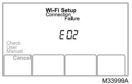
For certain problems, the thermostat screen will display a code that identifies the trouble. Initially, error codes are displayed alone in the time area of the screen; after a few minutes, the home screen is displayed and the code alternates with the time.
| E01 | During Wi-Fi Setup, the router lost power. | • Ensure your router has power.
• If trying to connect to a hidden or manually added network, confirm the router has power and is working. |
|
| E02 Invalid Wi-Fi password. This code displays for 30 seconds, then the thermostat will re- enter Wi-Fi Setup mode. | • Re-enter password for your home Wi-Fi network.
• Repeat setup process and confirm your password for your home Wi-Fi network. |
||
| E42 Router is not issuing an IP ad- dress to the thermostat. | • Wait for 30 minutes, connection can take several minutes.
• If still no connection, remove thermostat from wallplate for 10 seconds, then reconnect it. • Verify your router is correctly setup to automatically give IP addresses. |
M33998A | |
| E43 No internet connection. Ther- mostat cannot communicate to Total Connect Comfort. | • Make sure the Internet cable is plugged in.
• Reboot the router. |
||
| E99 | General error | Remove thermostat from wallplate for 10 seconds, then recon- nect it. | |
If you have difficulty with your thermostat, please try the following suggestions. Most problems can be corrected quickly and easily.
Display is blank
- Check circuit breaker and reset if necessary.
- Make sure power switch at heating and cooling system is on.
- Make sure furnace door is closed securely.
- Make sure C wire is connected.
Fan does not turn on when heat is required
Check Function 3: Heating Fan Control to make sure it is set to match the heating equipment
Cool On or Heat On is flashing on the screen
Compressor protection feature is engaged. Wait 5 minutes for the system to restart safely, without damage to the compressor.
Heat pump issues cool air in heat mode, or warm air in cool mode
Check Function 2: Heat Pump Changeover Valve to make sure it is properly configured for your system.
Heating system is running in cool mode
Check Function 1: System Type to make sure it is set to match the heating and cooling equipment
Heating and cooling equipment are running at the same time
- Check Function 1: System Type to make sure it is set to match the heating and cooling equipment.
- Grasp and pull thermostat away from wallplate. Check to make sure bare wires are not touching each other.
- Check thermostat wiring is correct
Special functions
Auto Changeover (Setup Function 12): When set to Auto, the thermostat automatically selects heating or cooling depending on the indoor temperature. The thermostat will automatically adjust heat and cool settings to maintain a 3-degree separation (fixed). Note: If you select Auto Changeover Only, the System Setting on the thermostat will stay locked in the Auto position, preventing the user from changing it to Em Heat, Heat, Cool or Off.
Adaptive Intelligent Recovery™ (Setup Function 13): Allows the thermostat to “learn” how long the furnace and air conditioner take to reach programmed temperature settings, so the temperature is reached at the scheduled time.
Compressor Protection (Setup Function 15): Forces the compressor to wait a few minutes before restarting, to prevent damage. During the wait time, the message Cool On or Heat On (heat pumps only) will flash on the display.
Accessories and replacement parts
Please contact your distributor to order replacement parts.
- Cover plate assembly Part Number 50002883-00112
- pack of medium cover plates Part Number 50007298-001
Specifications
MERCURY NOTICE
If this product is replacing a control that contains mercury in a sealed tube, do not place the old control in the trash. Contact your local waste management authority for instructions regarding recycling and proper disposal.
CAUTION: ELECTRONIC WASTE NOTICE
The product should not be disposed of with other household waste. Check for the nearest authorized collection centers or authorized recyclers. The correct disposal of end-of-life equipment will help prevent negative consequences for the environment and human health.
Resideo Technologies, Inc. 1985 Douglas Drive North, Golden Valley, MN 55422 1-800-468-1502 69-2738EFS—05 M.S. Rev. 02-22 | Printed in United States www.resideo.com
© 2022 Resideo Technologies, Inc. All rights reserved. The Honeywell Home trademark is used under license from Honeywell International, Inc. This product is manufactured by Resideo Technologies, Inc. and its affiliates.