Plug and Play Temperature Controller

Website: www.ink-bird.com
Email:

Safety Precautions
- Please read the specification carefully before using the product.
- Do not touch the terminals at least while power is being supplied. This could lead to electric shock.
- Do not allow pieces of metal, wire clippings, or fine metallic shaving or filings from installation to enter the product. This can result in electric shock, fire, or malfunction.
- Keep the product away from heat sources such as fires, flammable or explosive gas, etc. This may lead to the generation of excessive heat, ignition, and explosion.
- Never disassemble, modify or repair the product or touch any of the internal parts. This can result in electric shock, fire, or malfunction.
- If the output relays are used over their life expectancy, contact fusing or burning may occasionally occur. Always consider the application conditions and use the output relays within their rated load and electrical life expectancy. Do not immerse the product in water/ seawater.
Overview
What is ITC-308?
ITC-308 is an easy-to-use, safe, and reliable dual relay output temperature controller. It can be used as over-temperature protection and automatic temperature control system for various electric appliances such as equipment for home-brewing, aquarium, pet breeding, incubation, BBQ, seedling heat mats, oven temperature control, terrestrial heat control, constant temperature cycle of the heating pump, culture fermentation, accelerating germination, electric radiator, electric oven, etc.
This product has a plug-n-play design with a dual relay, be able to connect with refrigeration and heating equipment easily to realize ideal temperature control. It’s equipped with a dual-LED display, and offers display options of Centigrade and Fahrenheit, enabling more humanized temperature control. With large output power 1200W (110V)/2200W(220V), it’s suitable for most applications.
Main features
- Plug and play design, easy to use;
- Dual relay output, be able to connect with refrigeration and heating equipment at the same time;
- Support reading with Centigrade or Fahrenheit unit;
- Maximum output load: 1200W(110V) / 2200W(220V);
- Dual display window, be able to display measured temperature and set temperature at the same time;
- Temperature calibration; Compressor delay protection for refrigeration control;
- High and low-temperature alarms are available;
- Over-temperature and sensor fault alarm;
- The heating/Cooling differential function could be set separately for refrigeration and heating to protect the temperature controller from violent change.
Specification
| Temperature Control Range | -50-120°C/-58-248°F |
| Temperature Resolution | 0.1 °C/ 0.1°F |
| Temperature Accuracy | ±1°C (-50 – 70°C) / ±2°F (-58 – 160° F) |
| Temperature Control Mode | On/Off Control, Heating and Cooling |
| Input Power | 100 -240VAC, 50Hz/60Hz |
| Temperature Control Output | Max. 10A, 100V -240V AC |
| Buzzer Alarm | High and Low-Temperature Alarm |
| Sensor Type | NTC sensor (Including) |
| Sensor Length | 2m / 6.56ft |
| Relay Contact Capacity | Heating (10A, 100-240VAC) |
| Cooling (10A, 100-240VAC) | |
| Input Power Cable Length | 1.5m ( 5ft ) |
| Ambient Temperature | -30-75 °C/ -22- 167 °F |
| Storage | Temperature: -20- 60 ° C / -4- 140 ° F |
| Humidity: 20-85% (No Condensate ) | |
| Dimension (Main Body) | 140x68x33mm (5.5×2.7×1.3 inch) |
| Warranty | 1 Year |
Keys Instruction
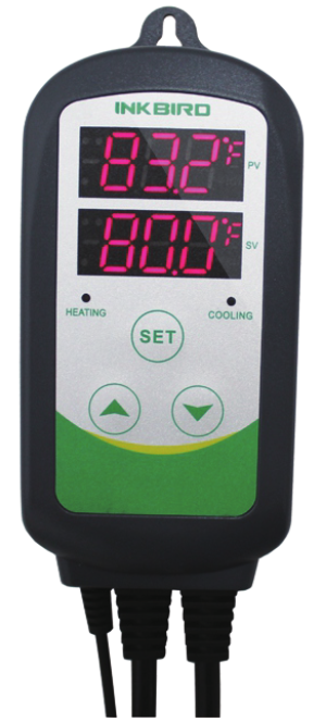
- PV: Process Value. under the running mode, display current temperature; under the setting mode, display menu code.
- SV: Setting Value. under the running mode, display setting temperature; under the setting mode, display setting value.
- Heating Indicator Light: when the light is on, start heating.
- Cooling indicator Light: when the light is on, start refrigeration; when the light is flickering, the compressor is under delay protection.
- SET key: press the SET key for 3 seconds to enter the menu for function setting. During the setting process, press the SET key for 3 seconds to quit and save setting changes.
- INCREASE key: under the running mode, press the INCREASE key to inquiry HD value; under the setting mode, press the INCREASE key to increasing value.
- DECREASE key: under the running mode, press the DECREASE key to inquiry CD value; under the setting mode, press the DECREASE key to decrease the value.
- Heating Device Socket: this socket is for heating output.
- Cooling Device Socket: the socket is for refrigeration output.
Key Operation Instruction
When the controller is working normally, short press “

How to Set Parameters
Step 1: While the controller working, start to set after pressing “SET” key for over 3 seconds. The indicator light will on.
Step 2: Make sure there are showing “TS” on PV window while setting the value.
Step 3: Setting parameters to your requirement by pressing “
Step 4: Saving parameters by pressing “SET” key over 3 seconds. Please notice that it will back to display mode and save nothing if you couldn’t set parameters within 10 seconds.
Setup Flow Chart

Menu Instruction
When the temperature is displayed in Centigrade.
| Menu code | Function | Setting range | Default setting | Remarks |
| TS | Temperature Set Value | -50-120°C | 25°C | |
| HD | Heating Differential Value | 0.3-15°C | 2.0°C | |
| CD | Cooling Differential Value | 0.3-15°C | 2.0°C | |
| AH | Alarm High Limit | -50-120°C | 90°C | |
| AL | Alarm Low Limit | -50-120°C | -40°C | |
| PT | Compressor Delay | 0-10 minutes | 0 | |
| CA | Temperature Calibration | -15°C-15°C | 0°C | |
| CF | Display in Fahrenheit or Centigrade | C |
| Menu code | Function | Setting range | Default setting | Remarks |
| TS | Temperature Set Value |
-58-248°F | 77°F | 6. |
| HD | Heating Differential Value |
1-30°F | 3°F | |
| CD | Cooling Differential Value |
1-30°F | 3°F | |
| AH | Alarm High Limit | -50-248°F | 200°F | 6. |
| AL | Alarm Low Limit | -50-248°F | -40°F | |
| PT | Compressor Delay | 0-10 minutes | 0 | 6. |
| CA | Temperature Calibration |
-15°F-15°F | 0°F | 6. |
| CF | Display in Fahrenheit or Centigrade |
7. | F |
When the measured temperature PV 
When the measured temperature PV 
When the measured temperature PV 
For example, set TS=25°C, CD=2°C, and HD=3°C, then when the measured temperature is higher or equal to 27°C (TS+CD), the system enters refrigeration status; when temperature decline to 25°C(TS), stop refrigeration; when measured temperature Is lower or equal to 22°C (TS-HD), the system enters heating status; when the temperature raised to 25°C(TS), stop heating.
In case the time interval between two refrigeration is less than PT, please refer to 6.3.
6.2 Alarm High/Low Limit Setting (AH, AL)
When the measured temperature is higher or equal to AH, the high-temperature alarm will be triggered, the buzzer will alarm with tone ‘bi-bi-Biii” until the temperature is lower than AH or any key is pressed.
When measured temperature is lower or equal to AL, a low-temperature alarm will be triggered, the buzzer will alarm with tone “bi-bi-Biii” until the temperature >AL or any key is pressed.
6.3 Compressor Delay (PT)
Under refrigeration mode, after power on, if the measured temperature is higher than the value of setting temperature (TS) plus cooling differential(CD), the equipment won’t start refrigeration immediately, but waiting for a delay time.
When the time interval between two refrigeration operations is larger than the preset delay, the equipment will start refrigeration immediately; when the time interval between two refrigeration is less than the preset delay, the equipment won’t start refrigeration until the preset delay is satisfied. Delay time will be calculated right after the moment of refrigeration stops.
6.4 Temperature Calibration (CA)
When there is a deviation between the measured temperature and actual temperature, use the temperature calibration function to align the measured temperature and actual temperature. The corrected temperature is equal to temperature before calibration plus corrected value(corrected value could be a positive value, 0 or negative value).
6.5 Display in Fahrenheit or Centigrade unit (CF)
Users can select display with Fahrenheit or Centigrade temperature value according to their own habit. The default setting is displayed with a Centigrade temperature value. For displaying with Fahrenheit temperature value, set CF value as F.
Attentions: when the CF value changed, all the setting values will be recovered to factory settings.
Error Description
Sensor Fault Alarm:
when the temperature sensor is in a short circuit or open loop, the controller will initiate sensor fault mode, and cancel all the actions. The buzzer will alarm, LED displays ER. Buzzer alarm could be dismissed by pressing any key. After faults solved, the system will return to normal working mode.
Over-temperature Alarm:
when the measured temperature exceeds the measuring range ( higher than 120 °C1248 °F or higher than 99 °C1210 °F ), the controller will initiate over-temperature alarm mode, and cancel all the actions. The buzzer will alarm, LED displays HL. Buzzer alarm could be dismissed by pressing any key. When the temperature returns to the measuring range, the system will return to normal working status.