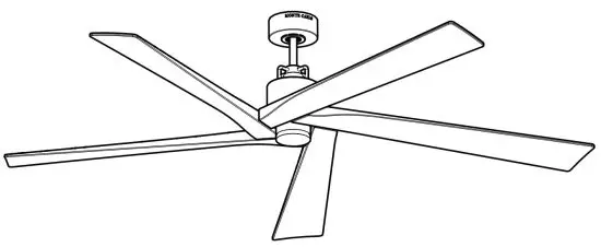
![]() 5ASPR70XXX Series Ceiling Fan
5ASPR70XXX Series Ceiling Fan
Owner’s Manual


Attach sales receipt to this card and retain as your proof of purchase
DATE OF PURCHASE: __________________
RETAILER NAME:______________________
MODEL NUMBER:______________________
RETAILER ADDRESS:___________________
To register your fixture, please visit our website www.montecarlofans.com

Cautions and Warnings
WARNING: TO REDUCE THE RISK OF FIRE, ELECTRIC SHOCK, OR INJURY TO PERSONS, OBSERVE THE FOLLOWING READ AND SAVE THESE INSTRUCTIONS
Installation work and electrical wiring must be done by qualified person(s) in accordance with applicable codes and standards (ANSI/NFPA 70), including fire-rated construction.
Use this unit only in the manner intended by the manufacturer. If you have any questions contact the manufacturer.
After making the wire connections, the wires should be spread apart with the grounded conductor and the equipment-grounding conductor on one side of the outlet box and the ungrounded conductor on the other side of the outlet box. The splices, after being made, should be turned upward and pushed carefully up into the outlet box.
WARNING: Before you begin installing the fan, servicing or cleaning the unit, switch power off at the Service panel and lock service disconnecting means to prevent power from being switched on accidentally. When the service disconnecting means cannot be locked, securely fasten a prominent warning device, such as a tag, to the service panel.
Be cautious! Read all instructions and safety information before installing your new fan. Review the accompanying assembly diagrams.
When cutting or drilling into a wall or ceiling, do not damage electrical wiring and other hidden utilities.
Make sure the installation site you choose allows the fan blades to rotate without any obstructions. Allow a minimum clearance of 7 feet from the floor to the trailing edge of the blade.
WARNING: To Reduce The Risk Of Fire, Electric Shock, or Personal Injury, Mount To Outlet Box Marked “Acceptable for Fan Support of 15.9 kg (35 lbs) or less” And Use Mounting Screws Provided With The Outlet Box.
WARNING: To reduce the risk of personal injury, do not bend blade holders during installation to the motor, balancing or during cleaning. Do not insert foreign objects between rotating blades.
CAUTION: For Compliance with Local Codes and Regulations, If Installing The Secondary Support Safety Cable in the U.S., Do Not Remove Knockouts In The Outlet Box. Mount the secondary support safety cable through the reserved nail/screw hole on the outlet box to the building structure (or the ceiling joist).
Attach the mounting bracket using only the hardware supplied with the outlet box.
WARNING: To Reduce The Risk Of Electric Shock, This Fan Must Be Installed With general use, isolating Wall Control/Switch.
WARNING: To reduce the risk of fire or electric shock, this fan should only be used with fan speed control part no. DC8 manufactured by Carewell Electric Technology (Zhongshan) Co., Ltd.
WARNING: To reduce the risk of fire or electric shock, do not use this fan with any other solid-state fan speed control device, or variable speed control.
If this unit is to be installed over a tub or shower, it must be marked as appropriate for the application.
Never place a switch where it can be reached from a tub or shower.
The combustion airflow needed for the safe operation of fuel-burning equipment may be affected by this unit’s operation. Follow the heating equipment manufacturer’s guideline safety standards such as those published by the National Fire Protection Association (NFPA), the American Society for Heating, Refrigeration and Air Conditioning Engineers (ASHRAE), and the local code authorities.
CAUTION: To Reduce the Risk of Electric Shock, Disconnect the electrical supply circuit to the fan before installing the light kit.
CAUTION: The light source is designed for this specific application and can overheat if serviced by untrained personnel. If any servicing is required, the product should be returned to an authorized service facility for examination or repair.
All set screws must be checked, and re-tightened where necessary, before installation.
Note: Suitable for use in damp locations.
Tools Required for Assembly (not included): Electrical Tape, Phillips Screwdriver, Pliers, Safety Glasses, Stepladder and Wire Strippers
Customer Service
800-969-3347
Customer Service Center
7400 Linder Ave.
Skokie, IL 60077
www.montecarlofans.com
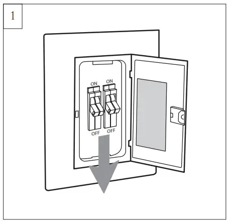
Before you begin installing the fan, Switch power off at the Service panel and lock service disconnecting means to prevent power from being switched on accidentally. When the service disconnecting means cannot be locked, securely fasten a warning device, such as a tag, to the service panel. Use AC 120V/60HZ power supply only.
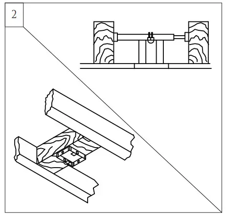
Before installing this fan make sure the outlet box is properly installed to the house structure. To reduce the risk of fire, electric shock, or personal injury, mount to outlet box or supporting system acceptable for fan support. (Mounting must support at least 35 lbs.)
Use a metal outlet box suitable for fan support and use only the screws provided with the outlet box (must support 35 lbs). Before attaching the fan to the outlet box, ensure the outlet box is securely fastened by at least two points to a structural ceiling member (a loose box will cause the fan to wobble). Remove the two outlet ox screws provided with the box, aligning the holes of the mounting bracket with the holes of the outlet box. Reinstall the 2 outlet box screws securely.
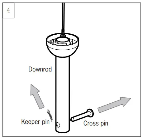
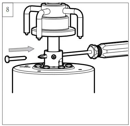
Remove preassembled keeper pin and cross pin from downrod. Keep parts.
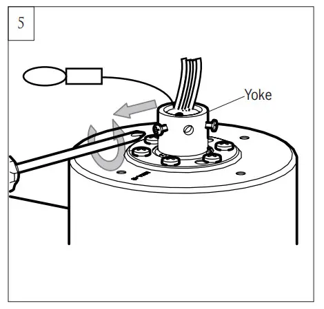
Partially loosen downrod set screws from yoke at top of the motor assembly.
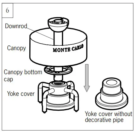
Place downrod over the canopy, canopy bottom cap, and yoke cover. An optional yoke cover without a decorative pipe was provided.
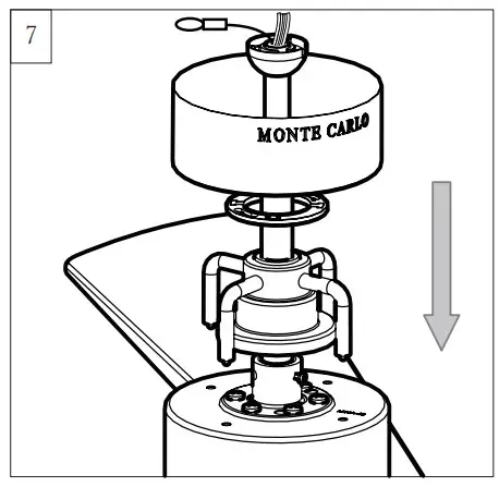
Thread lead wires and safety cable from motor assembly through downrod.
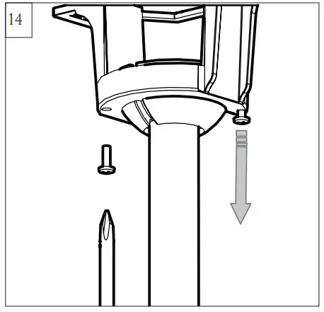
Helpful hint: For easy assembling of the cross pin on the next installation step. After slipping downrod into the motor yoke, carefully insert a Phillips screwdriver through the yoke and downrod (don’t damage the lead wires) as a guide and then push the cross pin and pull the screwdriver in the meantime as shown in the illustration.
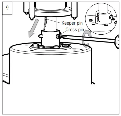
Slip downrod into motor housing yoke, aligning holes, and install cross pin and keeper pin.
Insert cross pin through yoke and downrod until point appears on the other side, and insert keeper pin on cross pin.
Pull the downrod up tight against the cross pin, and then evenly tighten the downrod set screws on the motor housing yoke.
Place Yoke cover on the motor assembly.
Warning: Cross pin and keeper pin must be installed securely, failure to install them will result in serious injury.
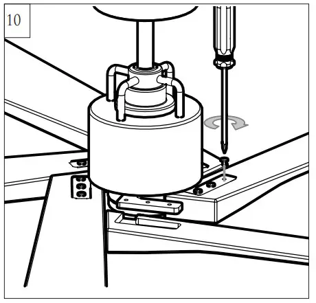
Place motor assembly on a suitable area of Styrofoam.
Align the holes on the blade and the screws holes on the blade bracket. Install the blades with set screws provided. Tighten all screws securely. Do not over tighten.
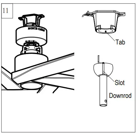
Install ball end of downrod into mounting bracket opening. Align (engage) slot on the ball with a tab on the mounting bracket.
Warning: Failure to align slot on the ball with tab may result in serious injury.
Important: If using the angle mount, make sure the open end of the mounting bracket is installed facing the higher point of the ceiling and make sure the ceiling angle is not steeper than 20º. A longer downrod may be necessary allowing the fan blades to rotate without obstructions.
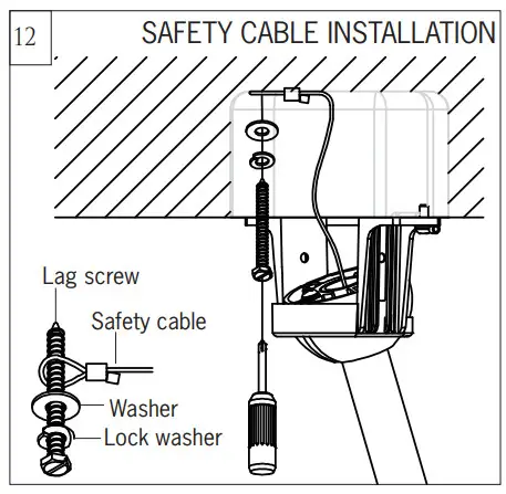
For Canadian installation and for USA fan and light kit combinations over 35 lbs, in both flush and downrod modes the safety cable must be installed into the house structure beams using 1.5” lag screws, washers, and lock washers provided. Make sure that when the safety cable is fully extended the lead wires are longer than the cable and no stress is placed on the lead wires.
Note: If Installing The Secondary Support Safety Cable in the U.S., Do Not Remove Knockouts In The Outlet Box.
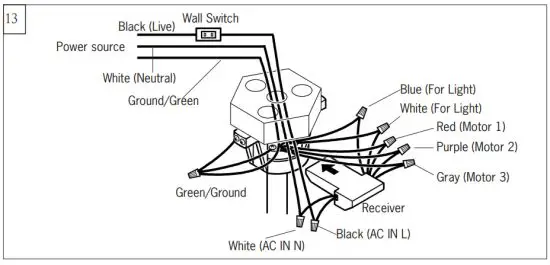
Make wiring connections using wire connectors provided as indicated above.
Red from fan to Red from remote marked Motor 1.
Purple from fan to Purple from remote marked Motor 2.
Gray from fan to Gray from remote marked Motor 3.
Blue from fan to Blue from remote marked FOR LIGHT.
White from fan to White from remote marked FOR LIGHT.
White (Neutral) from house to White from remote marked AC IN N.
Black (Live) from house to Black from remote marked AC IN L.
Connect all green grounded wires to Grounded wire from House.
Make sure that no filaments are outside of the wire connectors.
Insert the remote receiver into the mounting bracket.
After making the wire connections, the wires should be spread apart with the grounded conductor and the equipment-grounding conductor on one side of the outlet box and the ungrounded conductor on the other side of the outlet box. The splices after being made should be turned upward and pushed carefully up into the outlet box.
Partially loosen one and remove one preassembled screw from the mounting bracket. Save screw.
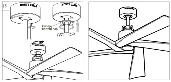
Lift canopy up, aligning its keyhole slot with the preassembled screw-on mounting bracket, and twist counterclockwise to lock in place.
Reinstall the screw removed in step 14 and tighten all screws securely. Attach canopy bottom cap onto canopy by aligning its notch with the screws on the mounting bracket and twist clockwise till tight.
REMOTE CONTROL SETTING and OPERATION
Transmitter Operation
![]() Remove the battery cover from the remote control transmitter and install a battery, battery provided. Replace the cover.
Remove the battery cover from the remote control transmitter and install a battery, battery provided. Replace the cover.
Note: Use 2 1.5V/AAA battery.
Note: If not used for a long period of time, remove the battery to prevent damage to the remote transmitter, and store the remote transmitter away from excess
heat or humidity.
Dimming / Non Dimming Setting
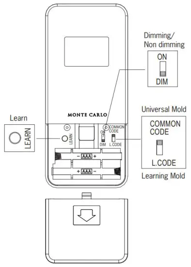 The “DIM” selection is the light dimmable selection and the light will cycle from bright to dim to bright until the button is released. The “ON” selection is the
light ON/OFF only (non-dimming function). Light will maintain the last setting if turned off.
Note: The remote controller is set with dimming function at the factory,
Note: If the remote receiver has been wired with a fan, turn the power off by wall switch before switching the “DIM” and “ON/OFF” selection.
Universal Mode and Learning Mode
There are “Universal Model” and “Learning Mode” with the remote controller.
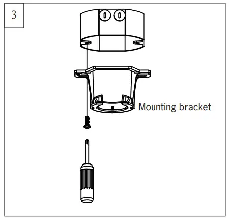
If choosing “Universal Mode”, simply place the dip (code) switch at the UPPER position. Your fan with the remote controller is ready to use.
Note: If using the universal mode, your fan can be controlled with other remote transmitters with the same setting.
To control the fan with a specific remote transmitter, choose “Learning Mode” by placing the dip (code) switch at the LOWER position and then make learn function setting as below.
Learn function setting, Restore power source to your fan, press and hold the “LEARN” button for at least 3 seconds. You must press the “LEARN” button within 60 seconds of restoring power to the fan.
Note: If the power is on already, you must turn the power off for 10 seconds at least, and then turn the power back for remote control learn function setting.
Note: If the fan is installed with light, the light will twinkle 2 times. The remote control setting process is complete and your fan is ready for use. For fans without light, check operation using a remote transmitter.
Note: If you want to control the fan with another transmitter, make the same setting. A fan can be controlled by 2 transmitters maximum.
The receiver provides the following protective functions
Lock protection- The DC motor has a built-in safety feature against blade or motor obstruction during operation. If something obstructs the fan blades or motor, the motor will keep trying to run for 5 times and then stop operation after about 60 seconds of interruption. Please remove obstacles and reset. To reset it by turn the fan off by remote transmitter and then turn the fan on, Or you may turn the power off for 15 seconds then turn the power back, and then turn the fan on,
Overload protection (current limit)- The device will limit the maximum current output from the receiver/drive when the fan or light load was increased abnormally.
The buttons on the remote control transmitter control the fan speed and light as follows.
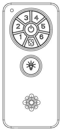
Fan speed
1 = minimum speed 2 = low speed
3 = medium-low speed 4 = medium speed
5 = medium high speed 6 = high speed
![]()
![]() Forward/Reverse button- This button is to control the direction of fan rotation. Press once to change the direction of the fan rotation. The fan must be running to reverse.
Forward/Reverse button- This button is to control the direction of fan rotation. Press once to change the direction of the fan rotation. The fan must be running to reverse.
![]() Light button (It is for fan with light)- Press this button to turn the light on or off. To dim light (Setting at “DIM” position), hold down the button, the light will cycle from bright to dim to bright until the button is released.
Light button (It is for fan with light)- Press this button to turn the light on or off. To dim light (Setting at “DIM” position), hold down the button, the light will cycle from bright to dim to bright until the button is released.
Note: This remote controller has an auto-resume function, the fan and light (If the fan with light) will maintain the last setting if power is turned off.
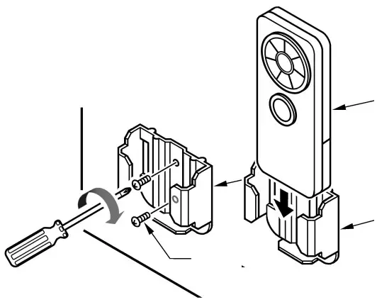
Wall mount cradle installation
Install Transmitter wall mount cradle with 2 screws provided.
THIS DEVICE COMPLIES WITH PART 15 OF THE FCC RULES OPERATION IS SUBJECT TO THE FOLLOWING TWO CONDITIONS. (1)THIS DEVICE MAY NOT CAUSE HARMFUL INTERFERENCE AND (2) THIS DEVICE MUST ACCEPT ANY INTERFERENCE RECEIVED, INCLUDING INTERFERENCE THAT MAY CAUSE UNDESIRED OPERATION.
Tips for end-users
- If your fan is operated automatically after installation and power on, it is because your fan is still memorized the previous setting at the factory.
- If the fan or light isn’t working, reset power (turn the power off for at least 10 seconds and then turn the power back) and redo the learn function setting.
- It is not available to separately operate the learn setting for more than one fan in the same room (in the area where the remote signal can reach) if they share the same power supply. Separate power supplies (like using individual wall switches for each fan and turning the power off for the fan while you are making learn function for another fan) are required if you want to separately control more than one fan in the same room.
- When the fan is turned on or operated forward/reverse function, it shutters & goes back & forth until it turns. It is a normal performance of this fan and it will take for few seconds to run this operation.
Trouble Shooting
If you have difficulty operating your new ceiling fan, it may be the result of incorrect assembly, installation, or wiring. In some cases, these installation errors may be mistaken for defects. If you experience any faults, please check this Trouble Shooting Chart. If a problem cannot be remedied, or you are experiencing difficulty in installation, please call our Customer Service Center at the number printed on your parts list insert sheet.
Warning: Before servicing or cleaning the unit, switch power off at the Service panel and lock service disconnecting means to prevent power from being switched on accidentally. When the service disconnecting means cannot be locked, securely fasten a prominent warning device, such as a tag, to the service panel.
| Trouble | Suggested Remedy |
| 1. If the fan does not start: | 1. Check main and branch circuit fuses or circuit breakers. 2. Check line wire connections to fan and switch wire connections in the switch housing. CAUTION: Make sure the main power is turned off. 3. If this fan uses a manual forward/reverse switch, make sure the switch is pushed firmly either way. The fan will not operate when the switch is in the middle. 4. If this fan uses a remote controller, make sure dip switches are set properly and make sure the battery is effective. |
| 2. If the fan sounds noisy: | 1. Check to make sure all screws in motor housing are snug (not overtightened). 2. Check to make sure the screws which attach the fan blade holder to the motor are tight. 3. Check to make sure wire nut connectors in switch housing are not rattling against each other or against the interior wall of the switch housing. CAUTION: Make sure the main power is turned off before entering switch housing. 4. Check to be sure the light bulb is tight in the socket and not touching the glass shade. 5. Some fan motors are sensitive to signals from Solid State variable speed controls. 6. Allow a “break-in” period of 24 hours. Most noises associated with a new fan will disappear after this period. |
| 3.If the fan wobbles: | 1. If this is a downrod mount fan, make sure the ridge on the mounting bracket engages the notch in the downrod ball. 2. Make sure that canopy, mounting bracket, or mounting plate are tightened securely to the ceiling junction box and junction box is mounted firmly to a ceiling joist. 3. Check that all blades are screwed firmly into blade holders. 4. Check that all blade holders are tightened securely to the motor. 5. Most fan wobble problems are caused when blade levels are unequal. Check this level by selecting a point on the ceiling above the tip of one of the blades. Measure this distance from blade tip to ceiling. Keeping measure within 1/8″, rotate the fan until the next blade is positioned for measurement. Repeat for each blade. If all blade levels are not equal, you can adjust blade levels by the following procedure. To adjust a blade tip down, insert a washer (not supplied) between the blade and blade holder at the screw closest to the motor. To adjust a blade tip up, insert a washer (not supplied) between the blade and blade holder at the two screws farthest from the motor. Reverse the position of the washer if blades mount from the top of the blade. 6. If blade wobble is still noticeable, interchanging two adjacent (side by side) blades can redistribute the weight and possibly result in a smoother operation. If the above steps do not eliminate the wobble problem, you will need to dynamic balance your fan with the balancing kit provided. |
| 4. If the light does not work: | 1. Check blue wire from the fan to make sure it is connected to hotwire from the house. 2. Check for loose or disconnected wires in the fan switch housing. 3. Check for loose or disconnected wires in the light kit. 4. Check for the faulty light bulbs and make sure the bulb is tight in the socket. 5. Remove light kit and check the plug connections if they are present. 6. If this fan uses a remote controller, make sure dip switches are set properly and make sure the battery is effective. CAUTION: Make sure the main power is turned off before entering switch housing and/or canopy. |
Jan.2021