MSI Motherboard
MSI Motherboard
Safety Information
- The components included in this package are prone to damage from electrostatic discharge (ESD). Please adhere to the following instructions to ensure successful computer assembly.
- Ensure that all components are securely connected. Loose connections may cause the computer to not recognize a component or fail to start.
- Hold the motherboard by the edges to avoid touching sensitive components.
- It is recommended to wear an electrostatic discharge (ESD) wrist strap when handling the motherboard to prevent electrostatic damage. If an ESD wrist strap is not available, discharge yourself of static electricity by touching another metal object before handling the motherboard.
- Store the motherboard in an electrostatic shielding container or on an anti-static pad whenever the motherboard is not installed.
- Before turning on the computer, ensure that there are no loose screws or metal components on the motherboard or anywhere within the computer case.
- Do not boot the computer before installation is completed. This could cause permanent damage to the components as well as injury to the user.
- If you need help during any installation step, please consult a certified computer technician.
- Always turn off the power supply and unplug the power cord from the power outlet before installing or removing any computer component.
- Keep this user guide for future reference.
- Keep this motherboard away from humidity.
- Make sure that your electrical outlet provides the same voltage as is indicated on the PSU, before connecting the PSU to the electrical outlet.
- Place the power cord such a way that people can not step on it. Do not place anything over the power cord.
- All cautions and warnings on the motherboard should be noted.
- If any of the following situations arises, get the motherboard checked by service personnel:
- Liquid has penetrated into the computer.
- The motherboard has been exposed to moisture.
- The motherboard does not work well or you can not get it work according to user guide.
- The motherboard has been dropped and damaged.
- The motherboard has obvious sign of breakage.
- Do not leave this motherboard in an environment above 60°C (140°F), it may damage the motherboard.
Specifications
| CPU |
* Please go to intel.com for compatibility information. |
| Chipset | Intel® H510/ B560 chipset |
| Memory |
* Please refer to www.msi.com for more information on compatible memory. |
| Expansion Slots |
|
| Onboard Graphics |
* Available only on processors featuring integrated graphics. |
| Audio | Realtek® ALC897 Codec
|
| LAN | 1x Intel® I219V 1Gbps LAN controller |
| Storage |
* SATA4 will be unavailable when installing M.2 SATA SSD in the M2_1 slot. |
| USB |
|
| Internal Connectors |
|
| Back Panel Connectors |
|
| LED Feature |
|
| I/O Controller | NUVOTON NCT6687D-M Controller Chip |
| Hardware Monitor |
|
| Form Factor |
|
| BIOS Features |
|
| Software |
|
| MSI Center Features |
|
| Special Features |
|
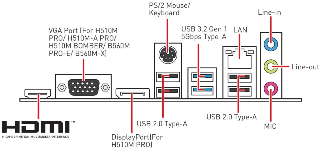
Rear I/O Panel
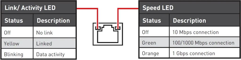
LAN Port LED Status Table
Audio 7.1-channel Configuration
To configure 7.1-channel audio, you have to connect front audio I/O module to JAUD1 connector and follow the below steps.
- Click on the Realtek HD Audio Manager > Advanced Settings to open the dialog below.
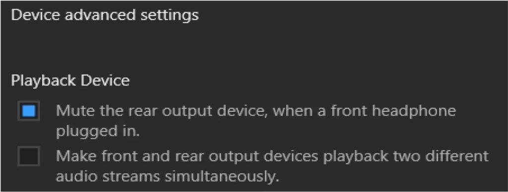
- Select Mute the rear output device, when a front headphone plugged in.
- Plug your speakers to audio jacks on rear and front I/O panel. When you plug into a device at an audio jack, a dialogue window will pop up asking you which device is current connected.
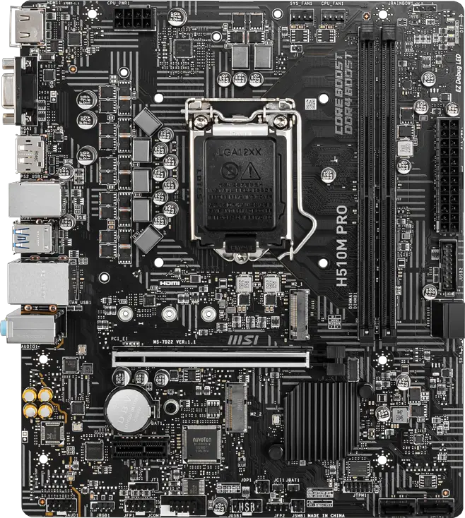
Overview of Components
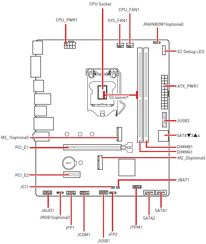
* Distance from the center of the CPU to the nearest DIMM slot.
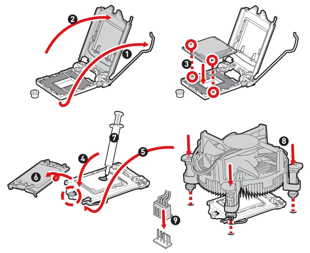
CPU Socket
Please install the CPU into the CPU socket as shown below.
Important
- Always unplug the power cord from the power outlet before installing or removing the CPU.
- Please retain the CPU protective cap after installing the processor. MSI will deal with Return Merchandise Authorization (RMA) requests if only the motherboard comes with the protective cap on the CPU socket.
- When installing a CPU, always remember to install a CPU heatsink. A CPU heatsink is necessary to prevent overheating and maintain system stability.
- Confirm that the CPU heatsink has formed a tight seal with the CPU before booting your system.
- Overheating can seriously damage the CPU and motherboard. Always make sure the cooling fans work properly to protect the CPU from overheating. Be sure to apply an even layer of thermal paste (or thermal tape) between the CPU and the heatsink to enhance heat dissipation.
- Whenever the CPU is not installed, always protect the CPU socket pins by covering the socket with the plastic cap.
- If you purchased a separate CPU and heatsink/ cooler, Please refer to the documentation in the heatsink/ cooler package for more details about installation.
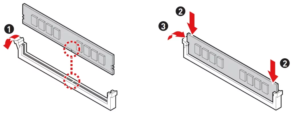
DIMM Slots
Please install the memory module into the DIMM slot as shown below.
Important
- To ensure system stability for Dual channel mode, memory modules must be of the same type, number and density.
- Some memory modules may operate at a lower frequency than the marked value when overclocking due to the memory frequency operates dependent on its Serial Presence Detect (SPD). Go to BIOS and find the DRAM Frequency to set the memory frequency if you want to operate the memory at the marked or at a higher frequency.
- It is recommended to use a more efficient memory cooling system for full DIMMs installation or overclocking.
- The stability and compatibility of installed memory module depend on installed CPU and devices when overclocking.
- Please refer to www.msi.com for more information on compatible memory.
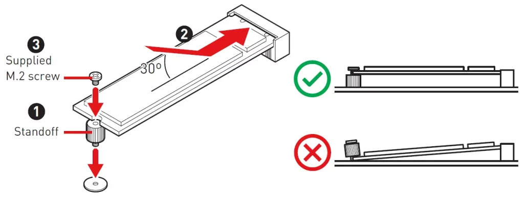
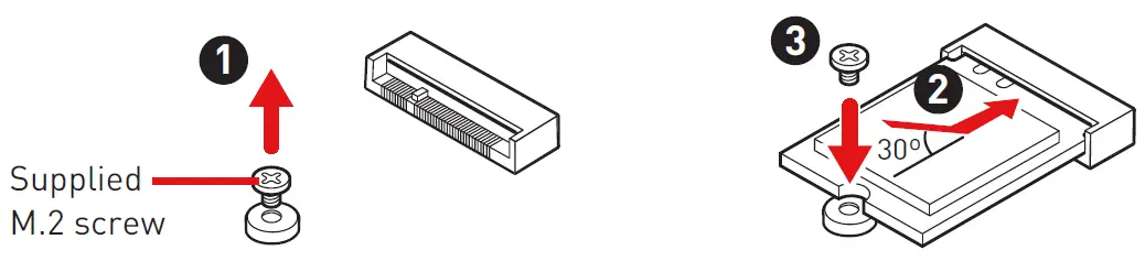
M2_1: M.2 Slot (Key M)
Please install the M.2 device into the M.2_1 slot as shown below.
M2_2: M.2 Slot (Key E)
Please install the Wi-Fi module into M.2_2 slot as shown below.
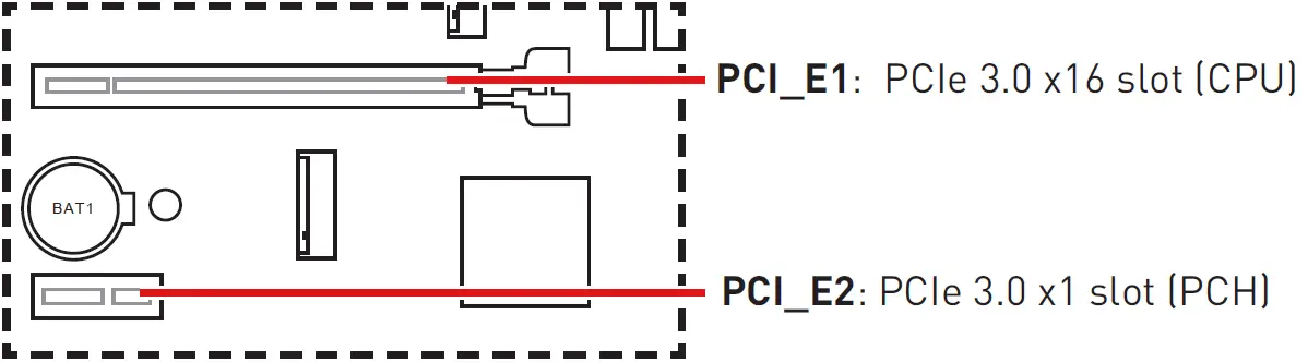
PCI_E1~2: PCIe Expansion Slots
Important
- When adding or removing expansion cards, always turn off the power supply and unplug the power supply power cable from the power outlet. Read the expansion card’s documentation to check for any necessary additional hardware or software changes.
- If you install a large and heavy graphics card, you need to use a tool such as MSI Gaming Series Graphics Card Bolster to support its weight to prevent deformation of the slot.
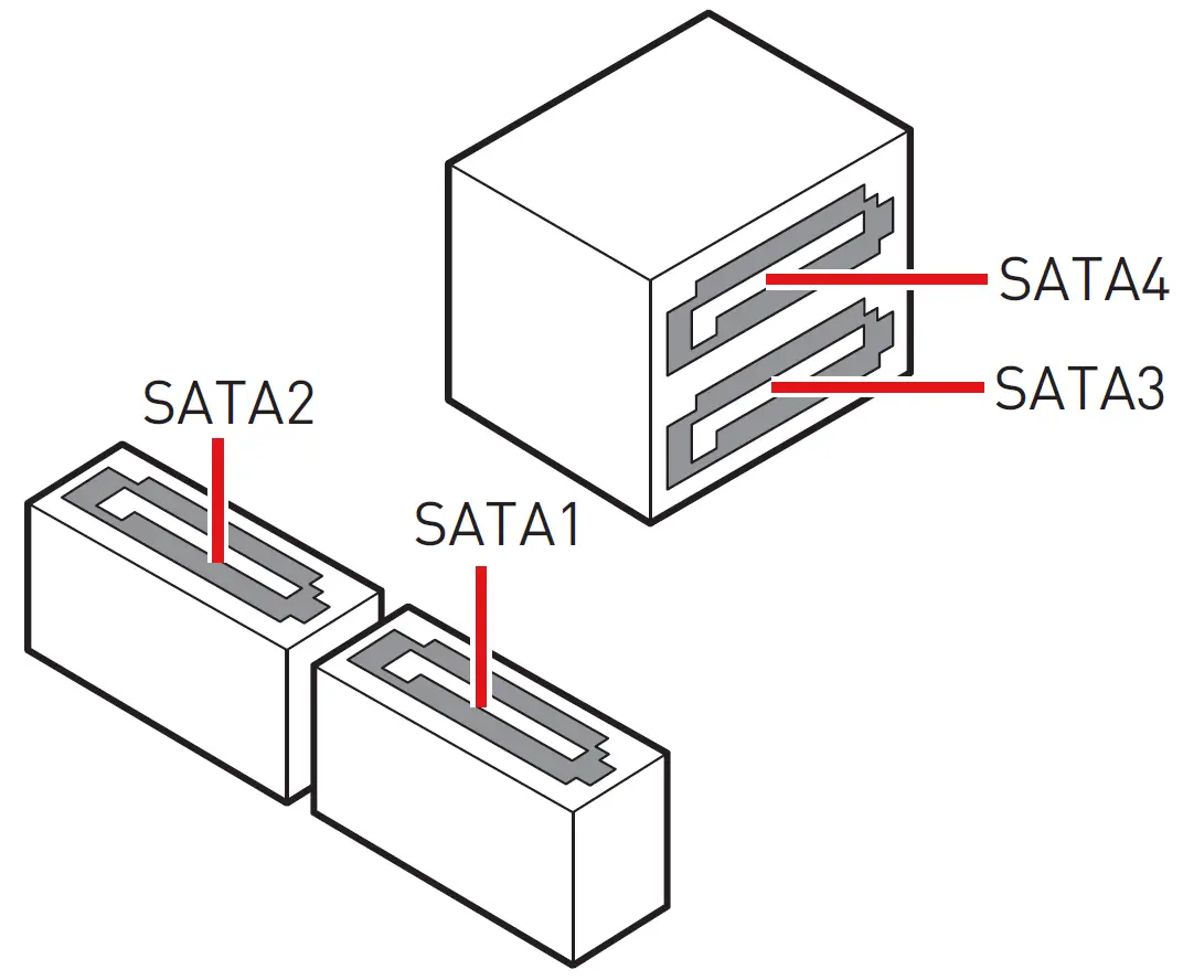
SATA1~4: SATA 6Gb/s Connectors
These connectors are SATA 6Gb/s interface ports. Each connector can connect to one SATA device.
Important
- Please do not fold the SATA cable at a 90-degree angle. Data loss may result during transmission otherwise.
- SATA cables have identical plugs on either sides of the cable. However, it is recommended that the flat connector be connected to the motherboard for space saving purposes.
- SATA1 will be unavailable when installing M.2 SATA SSD in the M2_1 slot.
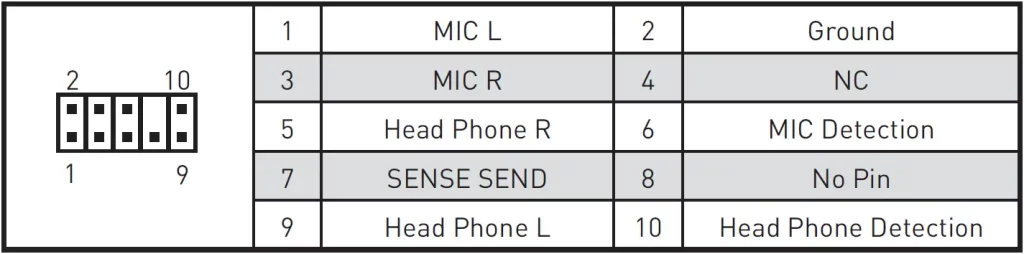
JAUD1: Front Audio Connector
This connector allows you to connect audio jacks on the front panel.
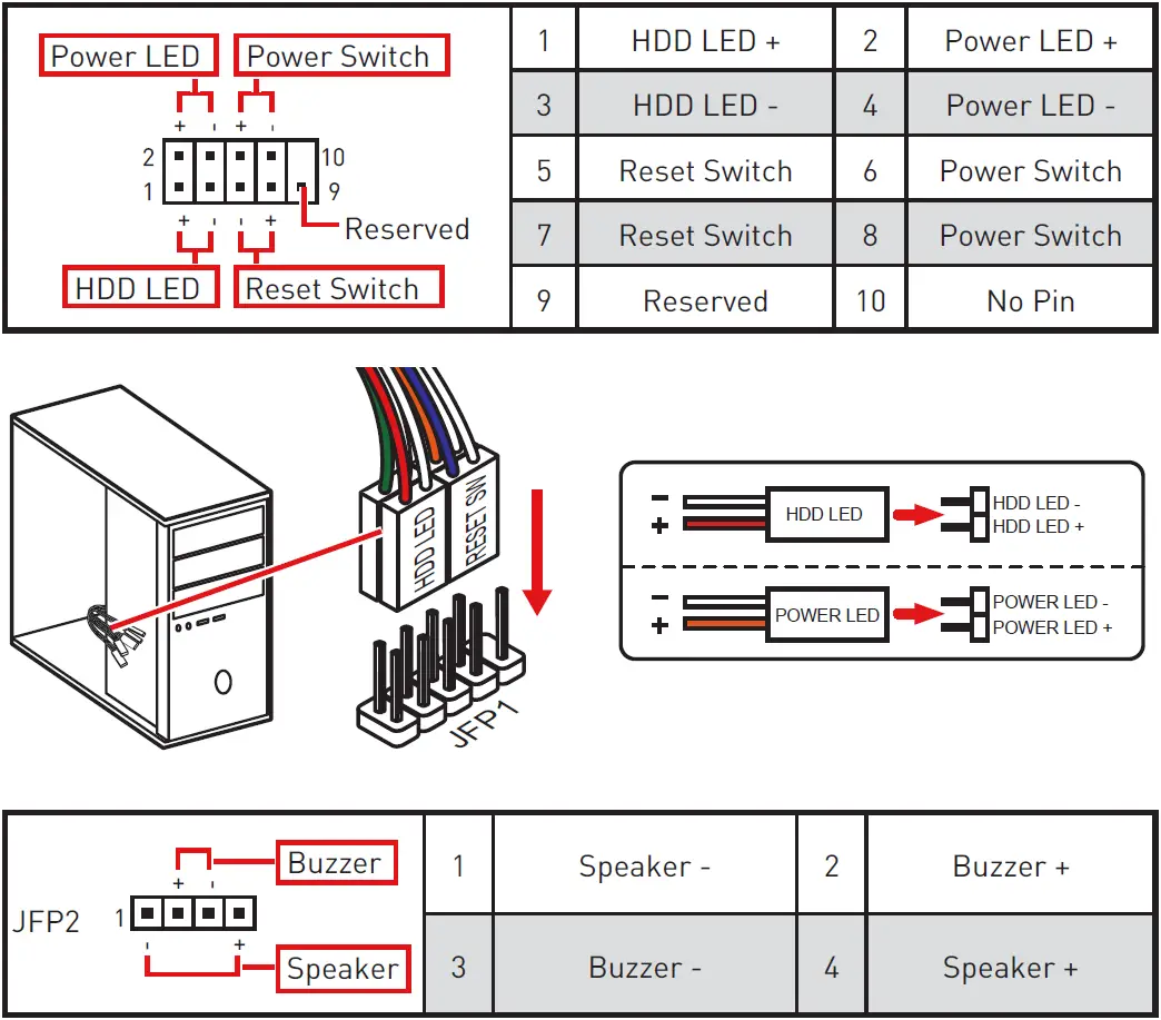
JFP1, JFP2: Front Panel Connectors
These connectors connect to the switches and LEDs on the front panel.
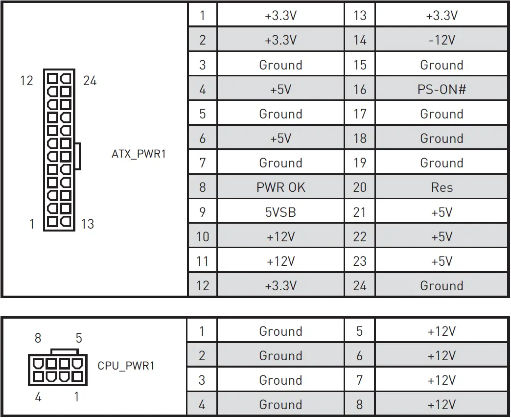
ATX_PWR1, CPU_PWR1: Power Connectors
These connectors allow you to connect an ATX power supply.
Important
Make sure that all the power cables are securely connected to a proper ATX power supply to ensure stable operation of the motherboard.
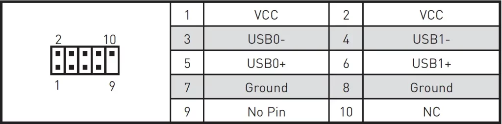
JUSB1: USB 2.0 Connector
This connector allows you to connect USB 2.0 ports on the front panel.
Important
- Note that the VCC and Ground pins must be connected correctly to avoid possible damage.
- In order to recharge your iPad, iPhone and iPod through USB ports, please install MSI® Center utility.
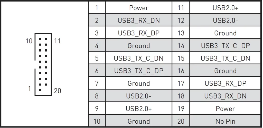
JUSB2: USB 3.2 Gen 1 5Gbps Connector
This connector allows you to connect USB 3.2 Gen 1 5Gbps ports on the front panel.
Important
Note that the Power and Ground pins must be connected correctly to avoid possible damage.
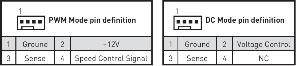
CPU_FAN1, SYS_FAN1: Fan Connectors
PWM Mode fan connectors provide constant 12V output and adjust fan speed with speed control signal. When you plug a 3-pin (Non-PWM) fan to a fan connector in PWM mode, the fan speed will always maintain at 100%, which might create a lot of noise.
| Connector | Default fan mode | Max. current | Max. power |
| CPU_FAN1 | PWM mode | 2A | 24W |
| SYS_FAN1 | DC mode | 1A | 12W |
Important
You can adjust fan speed in BIOS > Hardware Monitor.
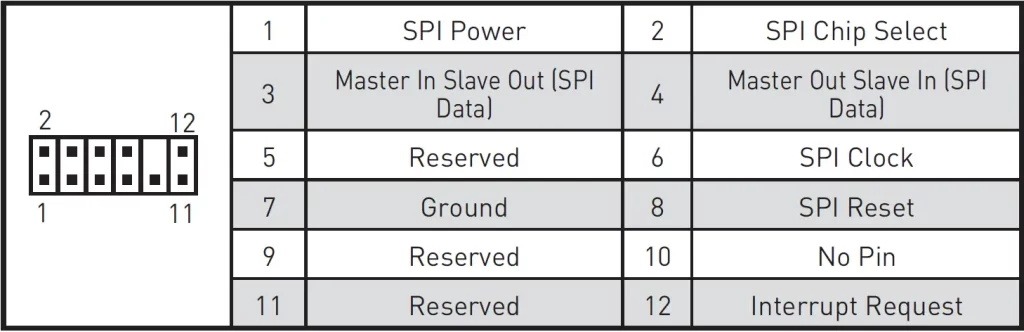
JTPM1: TPM Module Connector
This connector is for TPM (Trusted Platform Module). Please refer to the TPM security platform manual for more details and usages.
JCI1: Chassis Intrusion Connector
This connector allows you to connect the chassis intrusion switch cable.

Using Chassis Intrusion Detector
- Connect the JCI1 connector to the chassis intrusion switch/ sensor on the chassis.
- Close the chassis cover.
- Go to BIOS > Security > Chassis Intrusion Configuration.
- Set Chassis Intrusion to Enabled.
- Press F10 to save and exit and then press the Enter key to select Yes.
- Once the chassis cover is opened again, a warning message will be displayed on screen when the computer is turned on.
Resetting the Chassis Intrusion Warning
- Go to BIOS > Security > Chassis Intrusion Configuration.
- Set Chassis Intrusion to Reset.
- Press F10 to save and exit and then press the Enter key to select Yes.
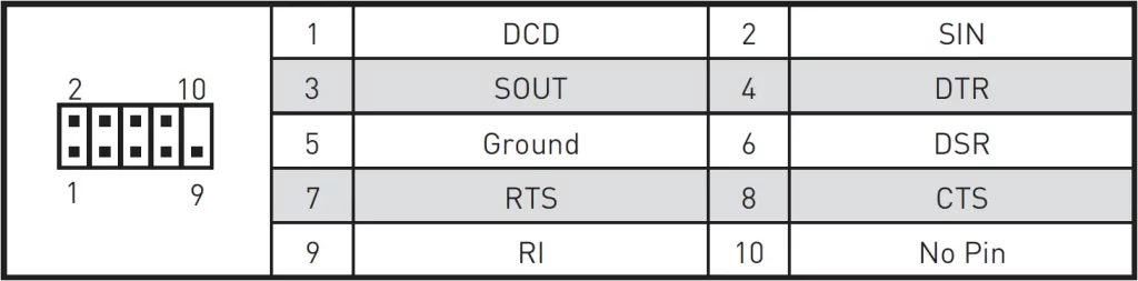
JCOM1: Serial Port Connector
This connector allows you to connect the optional serial port with bracket.
JBAT1: Clear CMOS (Reset BIOS) Jumper
There is CMOS memory onboard that is external powered from a battery located on the motherboard to save system configuration data. If you want to clear the system configuration, set the jumpers to clear the CMOS memory.

Resetting BIOS to Default Values
- Power off the computer and unplug the power cord.
- Use a jumper cap to short JBAT1 for about 5-10 seconds.
- Remove the jumper cap from JBAT1.
- Plug the power cord and power on the computer.
EZ Debug LED
These LEDs indicate the status of the motherboard.
- CPU – indicates CPU is not detected or fail.
- DRAM – indicates DRAM is not detected or fail.
- VGA – indicates GPU is not detected or fail.
- BOOT – indicates booting device is not detected or fail.
Installing OS, Drivers & MSI Center
Please download and update the latest utilities and drivers at www.msi.com
Installing Windows® 10
- Power on the computer.
- Insert the Windows ® 10 installation disc/USB into your computer.
- Press the Restart button on the computer case.
- Press F11 key during the computer POST (Power-On Self Test) to get into Boot Menu.
- Select the Windows ® 10 installation disc/USB from the Boot Menu.
- Press any key when screen shows Press any key to boot from CD or DVD… message.
- Follow the instructions on the screen to install Windows ® 10.
Installing Drivers
- Start up your computer in Windows® 10.
- Insert MSI® Drive disc into the optical drive.
- Click the Select to choose what happens with this disc pop-up notification, then select Run DVDSetup.exe to open the installer. If you turn off the AutoPlay feature from the Windows Control Panel, you can still manually execute the DVDSetup.exe from the root path of the MSI Drive disc.
- The installer will find and list all necessary drivers in the Drivers/Software tab.
- Click the Install button in the lower-right corner of the window.
- The drivers installation will then be in progress, after it has finished it will prompt you to restart.
- Click OK button to finish.
- Restart your computer.
MSI Center
MSI Center is an application that helps you easily optimize game settings and smoothly use content creation softwares. It also allows you to control and synchronize LED light effects on PCs and other MSI products. With MSI Center, you can customize ideal modes, monitor system performance, and adjust fan speed.
MSI Center User Guide
If you would like to know more information about MSI Center, please refer to http://download.msi.com/manual/mb/MSICENTER.pdf or scan the QR code to access.

Important
Functions may vary depending on the product you have.
UEFI BIOS
MSI UEFI BIOS is compatible with UEFI (Unified Extensible Firmware Interface) architecture. UEFI has many new functions and advantages that traditional BIOS cannot achieve, and it will completely replace BIOS in the future. The MSI UEFI BIOS uses UEFI as the default boot mode to take full advantage of the new chipset’s capabilities.
Important
The term BIOS in this user guide refers to UEFI BIOS unless otherwise noted.
UEFI Advantages
- Fast booting – UEFI can directly boot the operating system and save the BIOS self-test process. And also eliminates the time to switch to CSM mode during POST.
- Supports for hard drive partitions larger than 2 TB.
- Supports more than 4 primary partitions with a GUID Partition Table (GPT).
- Supports unlimited number of partitions.
- Supports full capabilities of new devices – new devices may not provide backward compatibility.
- Supports secure startup – UEFI can check the validity of the operating system to ensure that no malware tampers with the startup process.
Incompatible UEFI Cases
- 32-bit Windows operating system – this motherboard supports only 64-bit Windows 10 operating system.
- Older graphics card – the system will detect your graphics card. When display a warning message There is no GOP (Graphics Output protocol) support detected in this graphics card.
Important
We recommend that you to replace with a GOP/UEFI compatible graphics card or using integrated graphics from CPU for having normal function.
How to check the BIOS mode?
- Power on your computer.
- Press Delete key, when the Press DEL key to enter Setup Menu, F11 to enter Boot Menu message appears on the screen during the boot process.
- After entering the BIOS, you can check the BIOS Mode at the top of the screen.
BIOS Setup
The default settings offer the optimal performance for system stability in normal conditions. You should always keep the default settings to avoid possible system damage or failure booting unless you are familiar with BIOS.
Important
- BIOS items are continuously update for better system performance. Therefore, the description may be slightly different from the latest BIOS and should be for reference only. You could also refer to the HELP information panel for BIOS item description.
- The BIOS screens, options and settings will vary depending on your system.
Entering BIOS Setup
Press Delete key, when the Press DEL key to enter Setup Menu, F11 to enter Boot Menu message appears on the screen during the boot process.
Function key
- F1: General Help
- F2: Add/ Remove a favorite item
- F3: Enter Favorites menu
- F4: Enter CPU Specifications menu
- F5: Enter Memory-Z menu
- F6: Load optimized defaults
- F7: Switch between Advanced mode and EZ mode
- F8: Load Overclocking Profile
- F9: Save Overclocking Profile
- F10: Save Change and Reset*
- F12: Take a screenshot and save it to USB flash drive (FAT/ FAT32 format only).
- Ctrl+F: Enter Search page
* When you press F10, a confirmation window appears and it provides the modification information. Select between Yes or No to confirm your choice.
BIOS User Guide
If you’d like to know more instructions on setting up the BIOS, please refer to http://download.msi.com/manual/mb/Intel500BIOS.pdf or scan the QR code to access.

Resetting BIOS
You might need to restore the default BIOS setting to solve certain problems. There are several ways to reset BIOS:
- Go to BIOS and press F6 to load optimized defaults.
- Short the Clear CMOS jumper on the motherboard.
Important
Be sure the computer is off before clearing CMOS data. Please refer to the Clear CMOS jumper/ button section for resetting BIOS.
Updating BIOS
Updating BIOS with M-FLASH
Before updating:
Please download the latest BIOS file that matches your motherboard model from MSI website. And then save the BIOS file into the USB flash drive.
Updating BIOS:
- Insert the USB flash drive that contains the update file into the USB port.
- Please refer the following methods to enter flash mode.
- Reboot and press Ctrl + F5 key during POST and click on Yes to reboot the system.
- Reboot and press Del key during POST to enter BIOS. Click the M-FLASH button and click on Yes to reboot the system.
- Select a BIOS file to perform the BIOS update process.
- When prompted click on Yes to start recovering BIOS.
- After the flashing process is 100% completed, the system will reboot automatically.
Updating the BIOS with MSI Center
Before updating:
- Make sure the LAN driver is already installed and the internet connection is set properly.
- Please close all other application software before updating the BIOS.
To update BIOS:
- Install and launch MSI Center and go to Support page.
- Select Live Update and click on Advance button.
- Select the BIOS file and click on Install button.
- The installation reminder will appear, then click the Install button on it.
- The system will automatically restart to update BIOS.
- After the flashing process is 100% completed, the system will restart automatically.
FAQ’S
Is this motherboard compatible with my CPU?
Please refer to the specification page for the motherboard to check if your CPU is supported.
Does this motherboard support AMD AM3+ FX/AM3 Phenom™ II/Athlon™ II/Sempron™ processors?
Yes, it does.
How do I install a CPU on this motherboard?
Please refer to the user manual for your CPU for installation instructions.
How many SATA ports are there on this motherboard?
There are 4 SATA ports on this motherboard.
How many USB 2.0 ports are there on this motherboard?
There are 6 USB 2.0 ports on this motherboard.
How many USB 3.0 ports are there on this motherboard?
There are 2 USB 3.0 ports on this motherboard.
What is the most powerful motherboard for gaming?
The Best AMD Gaming Motherboards: X570(S), B550, TRX40, X470 and B450. AMD’s current flagship X570/X570S chipset brings with it full support for PCIe 4.0, including devices connected to both its CPU-integrated and chipset-based PCIe controllers, and the transfer rate between the CPU and chipset is likewise doubled.
Do motherboards matter for gaming?
Motherboards do not directly influence your gaming performance at all. What your motherboard type will do, is allow your graphics card and processor to perform better (or worse). It’s sort of similar to a Solid State Drive’s impact on FPS
What is the most powerful motherboard for gaming?
The Best AMD Gaming Motherboards: X570(S), B550, TRX40, X470 and B450. AMD’s current flagship X570/X570S chipset brings with it full support for PCIe 4.0, including devices connected to both its CPU-integrated and chipset-based PCIe controllers, and the transfer rate between the CPU and chipset is likewise doubled.
What makes a computer fast?
Having a processor with more cores and a higher clock speed means that you can interact with more applications, more quickly. Good ratings in these fields are what makes your computer faster. For the most rigorous routines, whether it’s gaming or video editing, 4.0 GHz is a good baseline for processor speed.
What RAM is compatible with MSI motherboard?
The minimum memory configuration is usually 8GB on most of MSI Desktop (DT). 8GB memory size is good for common usage.
How do I setup my Msi Gaming pc?
You can physically confirm that they are seated correctly by giving them a good push plug in the power cable to the back of your power supply. Some systems have a power switch that needs to be turned.
MSI Motherboard
www://msi.com/Motherboard/B560M-A-PRO
User Guide
3639 Killer Driver and Killer Control Center
Knowledge Base No. 3639
[How To] Uninstall/Install Killer driver and Killer Control Center
This document applies to all MSI notebooks with Killer Ethernet or Wireless adapters.
Prepare the driver install package
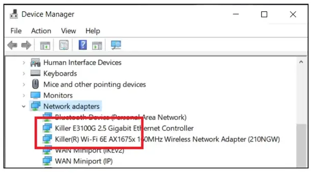
1. Check the Killer network adapter in the Device Manager
A. Use the keyboard shortcut “Windows + S” to open Search bar and search “Device Manager”.
B. Double-click on “Network Adapters” to expand the section.
C. Check the Killer network adapter.
 2. Download the Killer driver.
| Killer Network Adapter | Driver |
| Ethernet E3100, E3000, E3100G, E2500v2, E2600 Wireless 1550, AX1650, AX1675 |
Intel® Killer™ Performance Suite |
| Ethernet E2200, E2400, E2500 Wireless 1525, 1535, 1435 | Using Windows built-in driver Follow the instruction to uninstall the current driver, and then install Killer Control Center (UWP). |
Uninstall the current Killer driver and Killer Control Center
1. Disconnect the internet.
It prevents the Windows Update from installing the generic driver automatically.
2. Uninstall the Killer driver and related software completely.
A. Go to the “Apps & features” panel and search “Killer”.
Open Settings > Apps > Apps & features
B. Uninstall Killer Control Center and all the Killer-related driver suites listed on the search list.
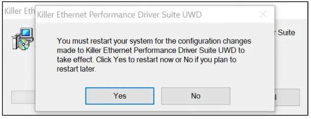
 C. Click on “Yes” when the uninstaller asks to restart the system. If selecting “No”, please restart the system manually.
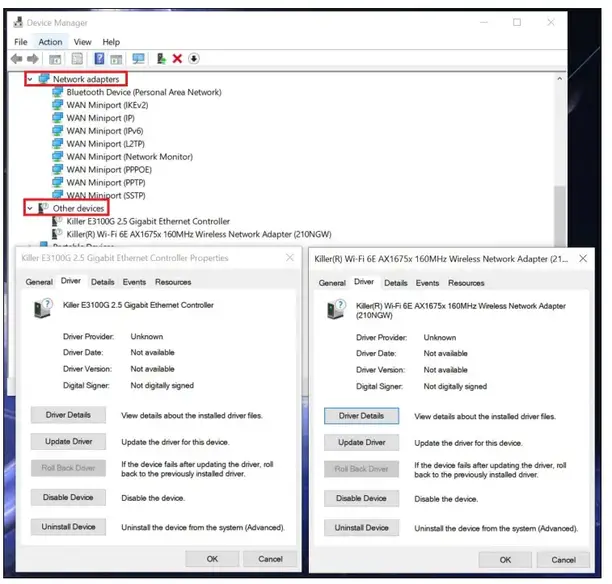
 D. Open Device Manager and check the Killer device in the “Network adapters” or “Other devices”.
The driver version will show “Not available” if the driver is uninstalled completely, and it means the driver is uninstalled completely.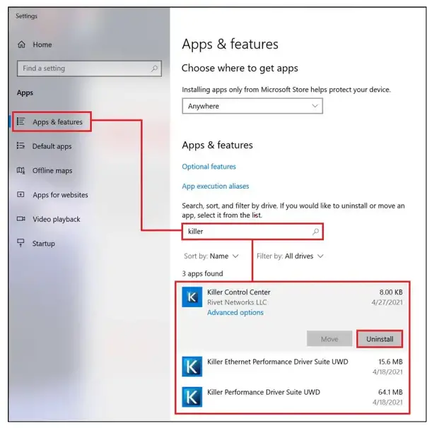 E. If the Killer network devices still show the driver version, follow the steps below to check the driver is uninstalled completely.
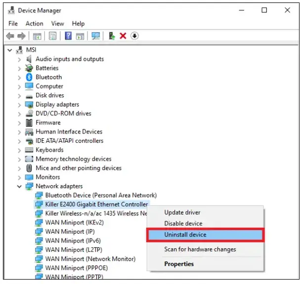
a. Right-click “Start” and click “Device Manager”.
b. Double-click on “Network Adapters” to expand the section.
c. Right-click the Killer network devices.
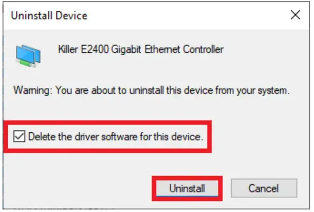
d. Click “Uninstall”.
 e. Check “Delete the driver software for this device” if this option is available and click “OK”.
 f. Repeat steps 1~5 until the “Delete the driver software for this device” is not available.
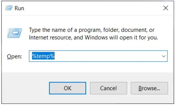
g. Press the Windows key + R, then type %Temp% and delete everything from that folder.
 Deleting the system temporary files helps to remove the related driver files.
Install the new Killer driver and Killer Control Center
1. Run the driver installer download on “step I” and follow the on-screen instructions to finish the installation.
For the following Killer adapters, please skip this step to keep using the Windows built-in driver.
Ethernet: E2200, E2400, E2500 & Wireless: 1525, 1535, 1435
2. Enable “Download Killer Control Center” to get the Killer Control Center (UWP)
Please connect the internet when the option shows up, and then click on “Finish”. This option will open the Microsoft Store download link of Killer Control Center (UWP) automatically.
 If you cannot get the download link of Killer Control Center (UWP) from the Killer installer, please download the Killer Control Center (UWP) by this Microsoft store download link.
 3. After the driver installer is finished, restart the system to complete the driver installation.
![]() MSI NB FAE Team
MSI NB FAE Team
Knowledge Base No. 003639
Date: 2022/8/1
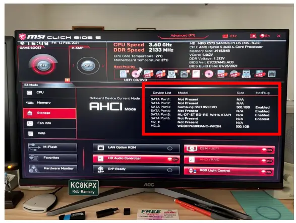
Context
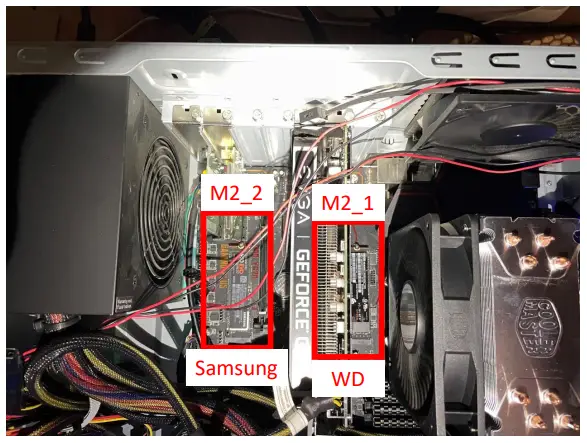
- System was built in April 2020 with only the Samsung Evo 970 M.2 drive installed (in M2_2 slot)
- System has been fully functional, running Windows 10 Pro, for 10 months
- Today (12 Feb 2021) I purchased and installed a new WD Black SN750 M.2 in the M2_1 slot
- The BIOS does not detect the WD M.2 in the M2_1 slot
- Testing revealed that neither M.2 is detected by the BIOS in the M2_1 slot
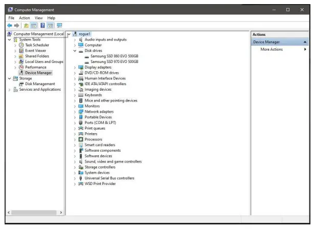
- The Windows 10 OS does not see the WD drive installed in the M2_1 slot after boot
Troubleshooting
Samsung 970 Evo M.2 in M2_1
WD Black SN750 M.2 in M2_2
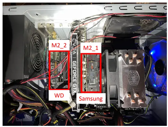
BIOS sees WD in M2_2 but does not see Samsung in M2_1
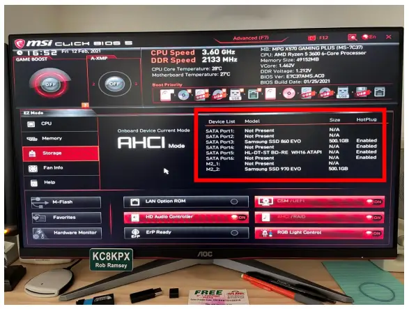
Samsung 970 Evo M.2 in M2_2
WD Black SN750 M.2 in M2_1
BIOS sees Samsung in M2_2
but does not see WD in M2_1
Note that the WD M.2 isn’t shown in Device Manager
Conclusion
- System sees both Samsung & WD M.2 drives in M2_2
- System does not see either M.2 drive in M2_1
- Either the M2_1 slot is bad, or a configuration setting needs to be changed
- MSI – Please advise on next trouble-shooting steps
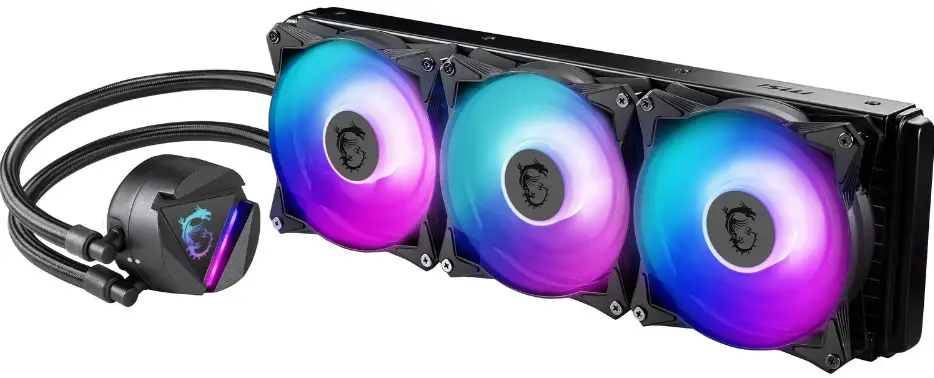
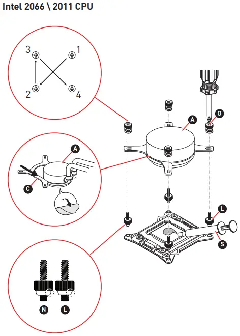
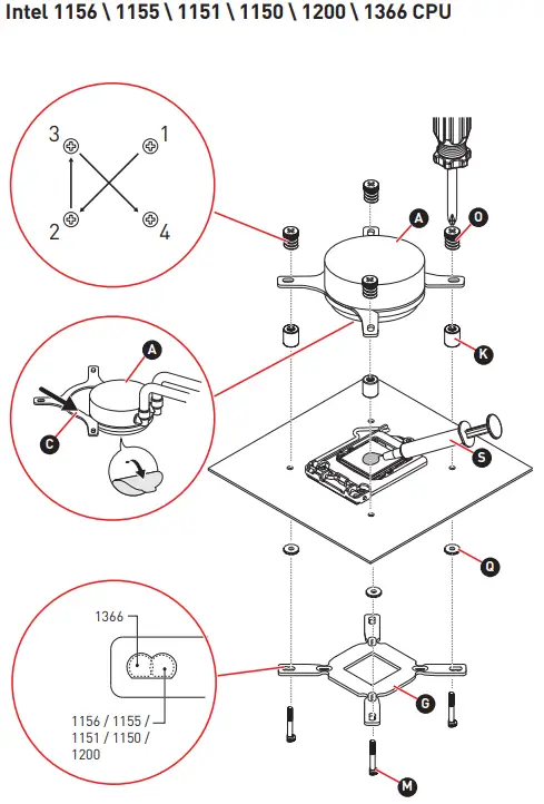
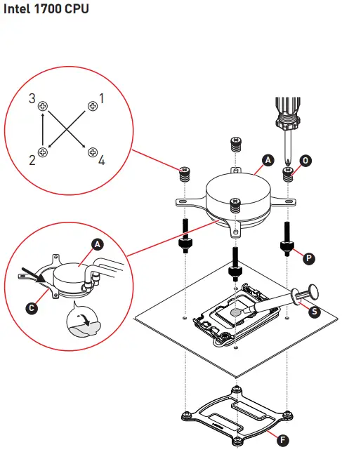
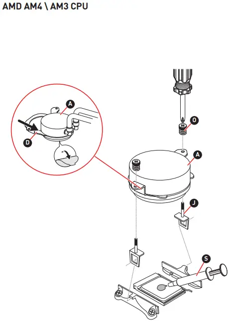
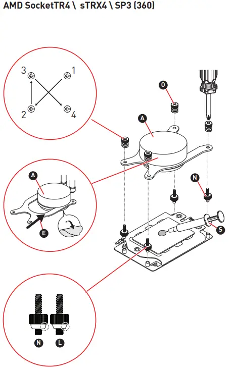
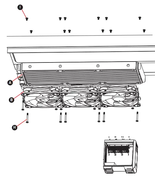
msi Mag Coreliquid 360r V2 Liquid CPU Cooler

The warranty term differs from one region to another. If you would like to verify the warranty term of the product bought, please kindly contact our local offices.
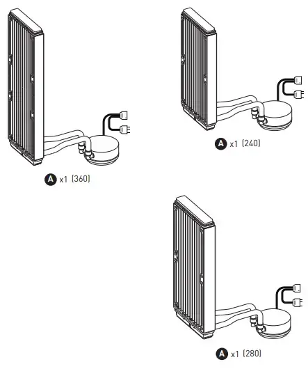
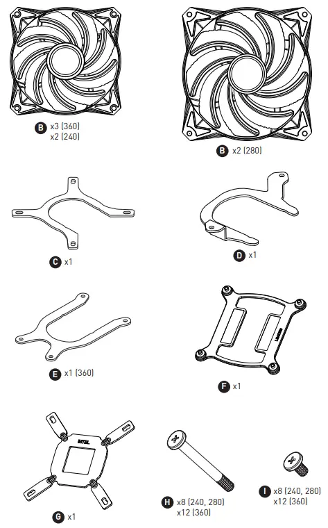
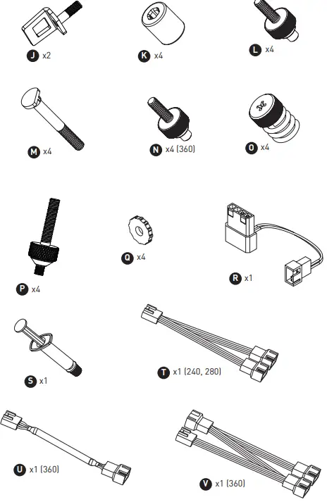
Packing Contents
Installation
Connection
Download
https:\msi.gmDC-manual
Software user guide
http://download.msi.com/manual/mb/MSICENTER.pdf
CE Conformity
Products bearing the CE marking comply with one or more of the following EU Directives as may be applicable:
- RED 201453EU; Low Voltage Directive 201435EU; EMC Directive 201430EU; RoHS Directive 201165EU.
- Compliance with these directives is assessed using applicable European Harmonized Standards.
- The point of contact for regulatory matters is MSI,
- MSI-NL Eindhoven 5706 5692 ER Son.
FCC-B Radio Frequency Interference Statement
This equipment has been tested and found to comply with the limits for a Class B digital device, pursuant to Part 15 of the FCC Rules. These limits are designed to provide reasonable protection against harmful interference in a residential installation. This equipment generates, uses and can radiate radio frequency energy and, if not installed and used in accordance with the instruction manual, may cause harmful interference to radio communications. However, there is no guarantee that interference will not occur in a particular installation. If this equipment does cause harmful interference to radio or television reception, which can be determined by turning the equipment off and on, the user is encouraged to try to correct the interference by one or more of the measures listed below:
- Reorient or relocate the receiving antenna.
- Increase the separation between the equipment and receiver.
- Connect the equipment into an outlet on a circuit different from that to which the receiver is connected.
- Consult the dealer or an experienced radiotelevision technician for help.
Notice 1
The changes or modifications not expressly approved by the party responsible for compliance could void the user’s authority to operate the equipment.
Notice 2
Shielded interface cables and AC power cord, if any, must be used in order to comply with the emission limits. This device complies with Part 15 of the FCC Rules. Operation is subject to the following two conditions:
- This device may not cause harmful interference, and
- This device must accept any interference received, including interference that may cause undesired operation.
MSI Computer Corp.
901 Canada Court, City of Industry, CA 91748, USA
(626) 913-0828 www.msi.com
Chemical Substances Information
In compliance with chemical substances regulations, such as the EU REACH Regulation
(Regulation EC No. 19072006 of the European Parliament and the Council), MSI provides the information of chemical substances in products at:
https:\storage-asset.msi.comhtmlpopupcsrevmtprtt_pcm.html
WEEE Statement
To protect the global environment and as an environmentalist, MSI must remind you that… Under the European Union (“EU”) Directive on Waste Electrical and Electronic Equipment, Directive 200296EC, which takes effect on August 13, 2005, products of “electrical and electronic equipment” cannot be discarded as municipal wastes anymore, and manufacturers of covered electronic equipment will be obligated to take back such products at the end of their useful life. MSI will comply with the product take-back requirements at the end of life of MSI-branded products that are sold into the EU. You can return these products to local collection points.
Green Product Features
- Reduced energy consumption during use and stand-by
- Limited use of substances harmful to the environment and health
- Easily dismantled and recycled
- Reduced use of natural resources by encouraging recycling
- Extended product lifetime through easy upgrades
- Reduced solid waste production through take-back policy
Environmental Policy
- The product has been designed to enable proper reuse of parts and recycling and should not be thrown away at its end of life.
- Users should contact the local authorized point of collection for recycling and disposing of their end-of-life products.
- Visit the MSI website and locate a nearby distributor for further recycling information.
- Users may also reach us at [email protected] for information regarding proper
Copyright and Trademarks Notice
Copyright © Micro-Star Int’l Co., Ltd. All rights reserved. The MSI logo used is a registered trademark of Micro-Star Int’l Co., Ltd. All other marks and names mentioned may be trademarks of their respective owners. No warranty as to accuracy or completeness is expressed or implied. MSI reserves the right to make changes to this document without prior notice.
Technical Support
If a problem arises with your product and no solution can be obtained from the user’s manual, please contact your place of purchase or local distributor. Alternatively, please visit https:\www.msi.comsupport for further guidance.
]]>Safety Instructions
 Read the safety instructions carefully and thoroughly
◙ All cautions and warnings on the device or user’s manual should be noted
◙ Refer servicing to qualified personnel only
 Keep the User’s Guide that comes with the package for future reference
 To prevent fire or shock hazard, keep this device away from humidity and high temperature
 Lay this device on a reliable flat surface before setting it up.
 ◙ Make sure that the power voltage is within its safety range and has been adjusted properly to the value of 100~240V before connecting the device to the power outlet Do not disable the protective earth pin from the plug The device must be connected to an earthed mains socket-outlet
◙ Always disconnect the power cord or switch the wall socket off if the device would be left unused for a certain time to achieve zero energy consumption
 The ventilator on the device is used for air convection and to prevent the device from overheating Do not cover the ventilator
 Do not leave the device in an unconditioned environment with a storage temperature above 60OC or below -20OC, which may damage the device
NOTE: The maximum operating temperature is around 40OC
 Place the power cord in a way that people are unlikely to step on it Do not place
anything on the power cord
 Always keep strong magnetic or electrical objects away from the device
 If any of the following situations arises, get the device checked by servicepersonnel:
- The power cord or plug is damaged
- Liquid has penetrated into the device
- The device has been exposed to moisture
- The device does not work well or you can not get it work according to user’s manual
- The device has dropped and damaged
- The device has obvious sign of breakage

- Reduced energy consumption during use and stand-by
- Limited use of substances harmful to the environment and health
- Easily dismantled and recycled
- Reduced use of natural resources by encouraging recycling
- Extended product lifetime through easy upgrades
- Reduced solid waste production through take-back policy Environmental Policy
- The product has been designed to enable proper reuse of parts and recycling and should not be thrown away at its end of life
- Users should contact the local authorized point of collection for recycling and disposing of their end-of-life products
- Visit the MSI website and locate a nearby distributor for further recycling information
- Users may also reach us at gpcontdev@msicom for information regarding proper disposal, take-back, recycling, and disassembly of MSI products
★ Warning! Overuse of screens is likely to affect eyesight.
★ Recommendations:
- Take a 10-minute break for every 30 minutes of screen time
- Children under 2 years of age should have no screen time For children aged
- years and over, screen time should be limited to less than one hour per day
 This device complies with the requirements set out in the Council Directive on the Approximation of the Laws of the Member States relating to Electromagnetic Compatibility (2014/30/EU), Low-voltage Directive (2014/35/EU), ErP Directive (2009/125/EC) and RoHS directive (2011/65/EU) This product has been tested and found to comply with the harmonized standards for
Information Technology Equipment published under Directives of Official Journal of the European Union
 FCC-B Radio Frequency Interference Statement
This equipment has been tested and found to comply with the limits for a Class B digital device, pursuant to Part 15 of the FCC Rules These limits are designed to provide reasonable protection against harmful interference in a residential installation This equipment generates, uses and can radiate radio frequency energy and, if not installed and used in accordance with the instruction manual, may cause
harmful interference to radio communications However, there is no guarantee that interference will not occur in a particular installation If this equipment does cause harmful interference to radio or television reception, which can be determined by turning the equipment off and on, the user is encouraged to try to correct the interference by one or more of the measures listed below:
- Reorient or relocate the receiving antenna
- Increase the separation between the equipment and receive
- Connect the equipment into an outlet on a circuit different from that to which the receiver is connected
- Consult the dealer or an experienced radio/television technician for help
Notice 1
The changes or modifications not expressly approved by the party responsible for
compliance could void the user’s authority to operate the equipment
Notice 2
Shielded interface cables and AC power cord, if any, must be used in order to comply
with the emission limits
This device complies with Part 15 of the FCC Rules Operation is subject to the following two conditions:
- this device may not cause harmful interference, and
- this device must accept any interference received, including interference that may cause undesired operation
WEEE Statement
 Under the European Union (“EU”) Directive on Waste Electrical and Electronic Equipment, Directive 2002/96/EC, which takes effect on August 13, 2005, products of “electrical and electronic equipment” cannot be discarded as municipal waste anymore and manufacturers of covered electronic equipment will be obligated to take back such products at the end of their useful life
Chemical Substances Information
In compliance with chemical substances regulations, such as the EU REACH Regulation (Regulation EC No 1907/2006 of the European Parliament and the Council), MSI
provides the information of chemical substances in products at: https://wwwmsicom/html/popup/csr/evmtprtt_pcmhtml
RoHS Statement
A Japanese regulatory requirement, defined by specification JIS C 0950, mandates that manufacturers provide material declarations for certain categories of electronic products offered for sale after July 1, 2006.
https://wwwmsicom/html/popup/csr/cemm_jphtml https://twmsicom/html/popup/csr_tw/cemm_jphtml
India RoHS
This product complies with the “India E-waste (Management and Handling) Rule 2011” and prohibits use of lead, mercury, hexavalent chromium, polybrominated biphenyls
or polybrominated diphenyl ethers in concentrations exceeding 01 weight % and 001 weight % for cadmium, except for the exemptions set in Schedule 2 of the Rule
Turkey EEE Regulation
Conforms to the EEE Regulations of the Republic Of Turkey
Ukraine Restriction of Hazardous Substances
The equipment complies with requirements of the Technical Regulation, approved by the Resolution of Cabinet of Ministry of Ukraine as of December 3, 2008 № 1057, in terms of restrictions for the use of certain dangerous substances in electrical and electronic equipment
Vietnam RoHS
As from December 1, 2012, all products manufactured by MSI comply with Circular 30/2011/TT-BCT temporarily regulating the permitted limits for a number of hazardous
substances in electronic and electric products
Package Contents
- Monitor
- Stand
- Stand Base with Screw
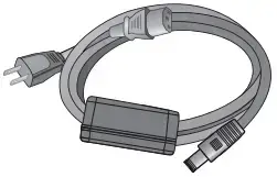
- Power Cord
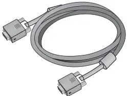
- HDMI Cable
- DisplayPort Cable
- Quick Start Guide
- Warranty Card
- Contact your place of purchase or local distributor if any of the items is damaged or missing
- Package contents may vary by country
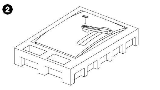
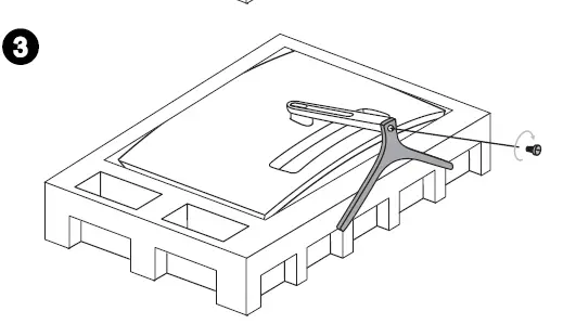
Installing the Monitor Stand
- Fit the stand to the monitor and tighten the stand with the screws
- Place the protection cover
- Connect the base to the stand and tighten the base screw to secure the base
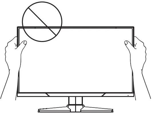
IMPORTANT
Place the monitor on a soft, protected surface to avoid scratching the display panel


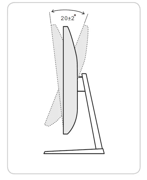
Adjusting the Monitor
This monitor is designed to maximize your viewing comfort with its adjustment capabilities
IMPORTANT
Avoid touching the display panel when adjusting the monitor
Monitor Overview
Connecting the Monitor to PC
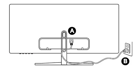
- Turn off your computer.
- Connect the DVI/HDMI/DisplayPort cable from the monitor to your computer
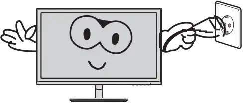
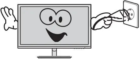
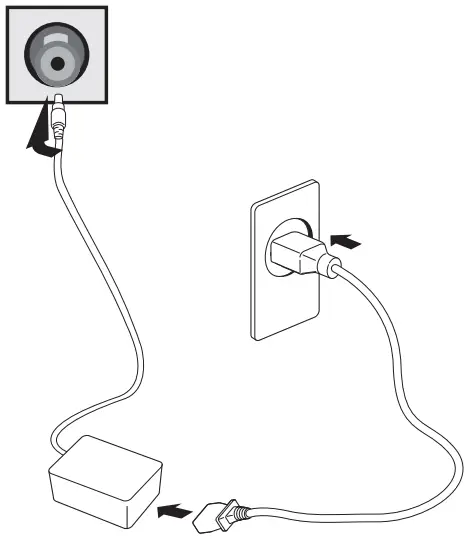
- Connect the power cord to the monitor power jack (Figure A)
- Plug the power cord into the electrical outlet (Figure B)
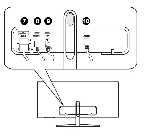
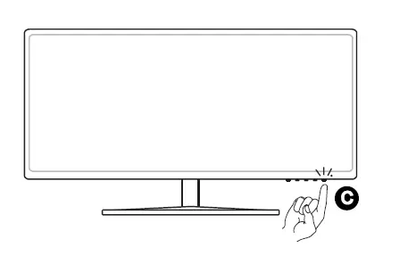
- Turn on the monitor (Figure C)
- Power on the computer and select your input source in OSD menu
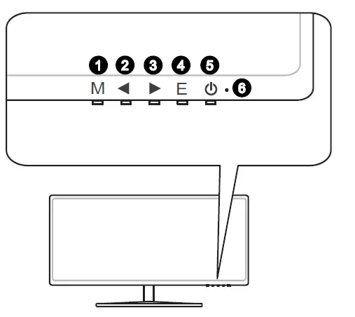
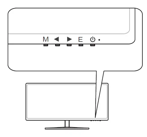
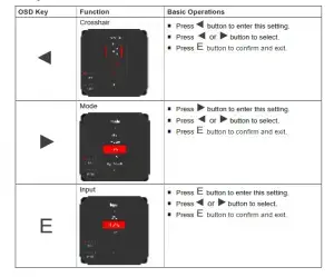
OSD Key
The monitor comes with a set of OSD Key that helps to control the On-Screen Display (OSD) menu
Without entering OSD menu, you can use these OSD keys as hot keys for quick seetings
OSD Setup Menu
Press M button to launch the On-Screen Display (OSD) main menu In OSD screen, use M E buttons to tune the desired function to suit your personal preferences
Game
| 1st Level Menu | 2nd/3rd Level Menu | Description |
| Mode | User | User mode (Default) |
| Movie | Movie mode | |
| FPS | First person shooting game mode | |
| RTS | Strategic game mode | |
| Eye Saver | Less blue light mode | |
| DCR | On | Turn on dynamic contrast function |
| Off | Turn off dynamic contrast function. | |
| FreeSync | On | Turn on FreeSync function(Supported by AMD
graphics card) |
| Off | Turn off FreeSync function. | |
| Aspect Ratio | Auto | Automatic aspect ratio |
| 21:9 | 21:9 aspect ratio | |
| 4:3 | 4:3 aspect ratio | |
| Crosshair | 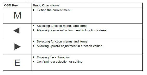 |
Red crosshair mode |
| White crosshair mode | ||
| Response Time | On | Turn on OD mode(Supported by monitor) |
| Off | Turn off OD mode. |
Image
| 1st Level Menu | 2nd/3rd Level Menu | Description | |
| Brightness | 0-100 | Adjust brightness Default is 90 | |
| Contrast | 0-100 | Adjust contrast Default is 50 | |
| Color Temp | Cool | Set as cold color temperature | |
| Warm | Set as warm color temperature | ||
| Customization | R (0-100) | Adjust red color temperature Default is 50 | |
| G (0-100) | Adjust green color temperature Default is 50 | ||
| B (0-100) | Adjust blue color temperature Default is 50 | ||
| Gamma | 18 | Adjust color tone brightness grey 18 | |
| 22 | Adjust color tone brightness grey 22 | ||
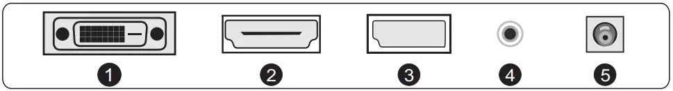
Input
| 1st Level Menu | Description |
| DVI | Select signal source from DVI port |
| HDMI | Select signal source from HDMI port |
| DP | Select signal source from DP port |
IP/PBP
| 1st Level Menu | 2nd/3rd Level Menu | Description |
| PIP | Source | DVI / HDMI / DP |
| PIP Size | Small / Medium / Large | |
| Location | Left Top / Right Top / Left Bottom / Right Bottom | |
| Display Switch | Display Switch allows users to switch between
primary and secondary input sources |
|
| PBP | Source | DVI / HDMI / DP |
| Display Switch | Display Switch allows users to switch between
primary and secondary input sources |
Setup
| 1st Level Menu | 2nd/3rd Level Menu | Description |
| Language | 繁中 | |
| English | ||
| Français | ||
| Deutsch | ||
| Italiano | ||
| Español | ||
| 한국어 | ||
| 日本語 | ||
| Русский | ||
| Português | ||
| (More languages coming
soon) |
||
| Transparency | 0-5 | Adjust transparency Default is 0 |
| Power Off | On | Turn on the automatic power off function if no signal. |
| Off | Turn off the automatic power off function. | |
| Reset | On | Reset to factory settings |
| Off | Exit from this item |
Specifications
| Model | Optix MAG341CQ | |
| Size | 34 inch | |
| Curvature | 1800R | |
| Panel Type | VA | |
| Resolution | 3440 x 1440@100Hz | |
| Aspect Ratio | 21:9 | |
| Brightness (nits) | 250 | |
| Contrast Ratio | 3000:1 | |
| Refresh Rate | 100Hz | |
| Response Time | 16ms (Typical)
8ms (GTG) |
|
| Input Interface | DVI x 1, HDMI 2 0 x1, DP x1 | |
| View Angles | 178°(H) , 178°(V) | |
| NTSC | 85% | |
| Surface Treatment | Anti-glare | |
| Display Colors | 167M | |
| Power Type | Built-in Adapter | |
| Power Consumption (Typical) | 60W | |
| Power Input | AC 100~240V, 50~60Hz | |
| Adjustment (Tilt) | -5° ~ 15° | |
| VESA Mounting | None | |
| Dimension (W x H x D) | 8184 x 452 x 1978 mm (Stand + Base) | |
| Net Weight | 71 kg (1565 lb) | |
| Environment | Operating | Temperature: 0°C to 40°C Humidity: 20% to 80%, non-condensing
Altitude: 0 ~ 2000m |
| Storage | Temperature: -20°C to 60°C
Humidity: 20% to 90%, non-condensing |
|
Preset Display Modes
| Resolution | Optix MAG341CQ | ||
| DVI | HDMI | DP | |
| 640×480 @60Hz | V | V | V |
| 640×480 @72Hz | V | V | V |
| 640×480 @75Hz | V | V | V |
| 800×600 @56Hz | V | V | V |
| 800×600 @60Hz | V | V | V |
| 800×600 @70Hz | V | V | V |
| 800×600 @75Hz | V | V | V |
| 800×600 @100Hz | V | V | V |
| 1024×768 @60Hz | V | V | V |
| 1024×768 @70Hz | V | V | V |
| 1024×768 @75Hz | V | V | V |
| 1024×768 @100Hz | V | V | V |
| 1280×1024 @60Hz | V | V | V |
| 1280×1024 @75Hz | V | V | V |
| 1280×1024 @100Hz | V | V | V |
| 1440×900 @60Hz | V | V | V |
| 1440×900 @100Hz | V | V | V |
| 1680×1050 @60Hz | V | V | V |
| 1680×1050 @100Hz | V | V | V |
| 1920×1080 @60Hz | V | V | V |
| 1920×1080 @100Hz | V | V | V |
| 3440×1440 @60Hz | V | V | V |
| 3440×1440 @100Hz | V | V | |
Troubleshooting
The power LED is off.
■ Press the monitor power button again
■ Check if the monitor power cable is properly connected
No image.
■ Check if the computer graphics card is properly installed
■ Check if the computer and monitor are connected to electrical outlets and are turned on
■ Check if the monitor signal cable is properly connected
■ The computer may be in Standby mode Press any key to activate the monitor
The screen image is not properly sized or centered.
Refer to Preset Display Modes to set the computer to a setting suitable for the monitor to display
No Plug & Play.
■ Check if the monitor power cable is properly connected
■ Check if the monitor signal cable is properly connected
■ Check if the computer and graphics card are Plug & Play compatible
The icons, font or screen are fuzzy, blurry or have color problems.
■ Avoid using any video extension cables
■ Adjust brightness and contrast
■ Adjust RGB color or tune color temperature
■ Check if the monitor signal cable is properly connected
■ Check for bent pins on the signal cable connector
The monitor starts flickering or shows waves.
■ Change the refresh rate to match the capabilities of your monitor
■ Update your graphics card drivers
■ Keep the monitor away from electrical devices that may cause
electromagnetic interference (EMI)
Safety Prevention Measures
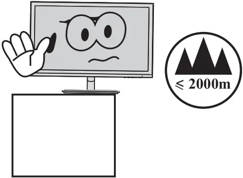
- Please always place this device on a stable surface; otherwise,
it may fall and be be damaged.

- The altitude and the tropical environment the adapter fits depend on which adapter is used for the device.
The rating plate on the back of the device with the above warning sign indicates that t h i s p r o d u c t i s applicable for the safe use of the region with a l t i t u d e o f 2,000m and below.

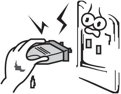
- Do not hold the plug w i t h w e t h a n d ; otherwise, electric shock may occur. Make sure the plug has a good touch because poor touch may cause fire.
- Do not use a broken power plug nor keep a power cord near heat source; otherwise, electric shock or fire may occur.
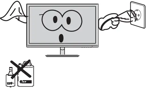
- When cleaning the device, be sure to remove the power plug, use a piece of soft cloth rather t h a n i n d u s t r i a l chemical to clean the device, be sure not to let water enter the device.
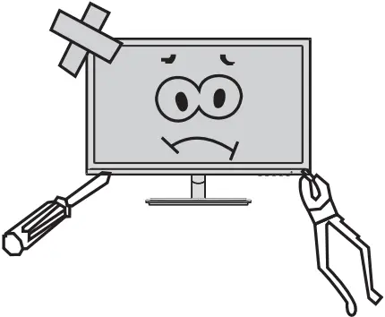
- Do not disassemble this device without permission. In case of failure, be sure to contact a professional servicing person to fix it.The unauthorized disassembly of this device may result in electric shock or fire.
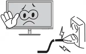
- In case of rare smell or noise out of this device, be sure to immediately cut off the power supply and ask a professional servicing person to fix the problem.
- When this device is idle for long time, be sure to power it off;otherwise,electric shock or fire may occur.
Note:
The device with AC switch may use such AC switch as cut-off component.
The device without AC switch may use power plug or coupler as cut-off component.
In case of the normal use of the equipment, make sure the cut-off component can be accessed easily.
Installation Instructions
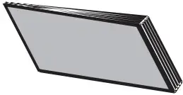
Accessories
- Power adapter
- Signal cable
- User manual
- Base/Stand

- Warranty card
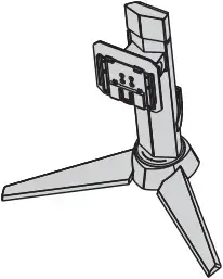
(The above pictures are for illustration only and the physical accessories shall govern.)
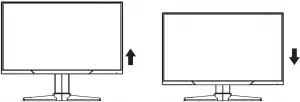
Adjustment of Rotation Angle
- The screen may be inclined 5° forward and 20°backward.
- The angle may be adjusted left and right within -30°-30°

- Vertical direction can be adjusted up and down within 65mm.
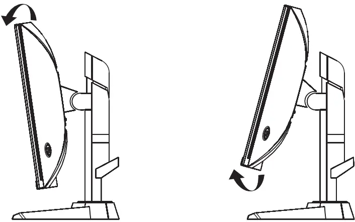
- When adjusting the angle of the display, be sure not to touch or press the screen area.
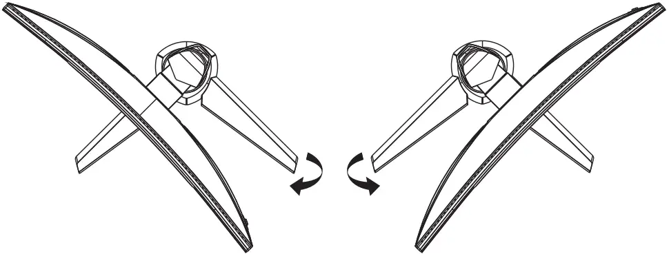
(The above pictures are for illustration only and the physical accessories shall govern.)
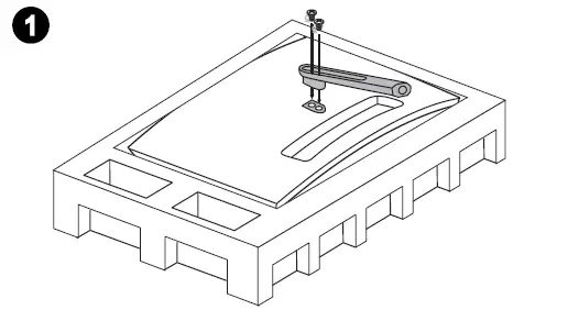
Project Assembly
See the assembly sketch on the cover of the packaging case.
Connect the Monitor to PC
Warning:
Before connecting the LCD monitor to the PC, please power down the PC and the monitor.
Power adapter
- Warning: Always use the power cord of standard configuration.
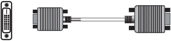
- DVI Port :
Connect the DVI cable into the DVI IN port in the back of the monitor (this needs the support of the monitor).
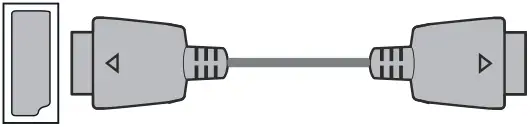
- HDMI Port :
Connect the HDMI cable into the HDMI IN port into the back of the monitor (this needs the support of the monitor).
- DP Port :
Connect the DP cable into the DP IN port of
the monitor (this needs the support of the monitor).
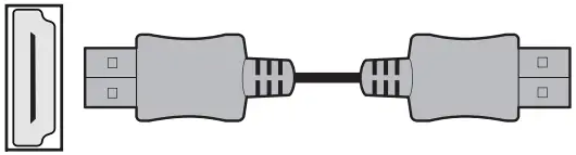
- Audio Interface
Connect the AUDIO cable to the AUDIO out port in the back of the display (this needs the support of the monitor).
- Power Plug
Connect the power cord of the monitor into the POWER port in the back of the monitor.
(The above pictures are for illustration only and the physical accessories shall govern.)
User Setup
Schematic Diagram of Keys
Description of Keys’ Functions
| 1. |  |
MENU key: Press this key to pop up the main menu/back to the previous menu (in case of main menu, exit). |
| 2. | 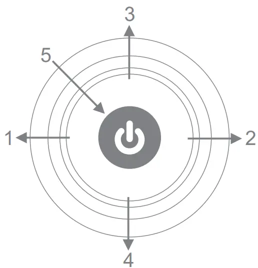 |
When a menu is open, press this key as the RIGHT key to enter the submenu; When no menu is open, press this key to switch to the desired signal input source. |
| 3. |  |
When a menu is open, press this key as the UP key to increase the progress bar value; When no menu is open, press this key to switch to the desired mode. |
| 4. |  |
When a menu is open, press this key as the DOWN key to decrease the progress bar value; When no menu is open, press this key to switch to the desired sight bead (with sight bead switch activated). |
| 5. |  |
POWER/MENU Key: Press this key shortly to pop up Main Menu/Confirm; hold this key to power off. |
| 6. | LED
Indicator |
Blue: Normal power-on state; Blinking blue: Power saver state. |
Note: The physical keys of the specific model shall govern.
Operation Menu (OSD) Function Descriptions
| First level menu item | Second level menu item | Third level menu item | Instructions | |
|
Game
|
Mode |
Standard | Normal use mode | |
| Movie | Application mode of seeing film | |||
| FPS | First person shooting game mode | |||
| RTS | Strategic game mode | |||
| Eye Saver | Eye-protecting blue light filtered application mode | |||
| DCR | Off | Inactivate dynamic contrast | ||
| On | Activate dynamic contrast | |||
|
FreeSync |
Off | Inactivate FreeSync function | ||
| On | Activate FreeSync function, only AMD display card supported (the support from the display is needed) | |||
|
Aspect ratio |
Auto | Automatic image scale adjustment | ||
| 16:9 | Adjust image to be wind screen | |||
| 4:3 | Adjust image to be 4:3 | |||
|
Crosshair |
None | Inactivate sight bead function | ||
 |
Switch to the red round sight bead | |||
 |
Switch to the green round sight bead | |||
 |
Switch to the red cross sight bead | |||
 |
Switch to the green cross sight bead | |||
|
Response time |
Off | OD off mode (the support from the display is needed) | ||
| Normal | OD general mode, reducing motion vague (the support from the display is needed) | |||
| Extreme | OD top speed mode, reducing motion vague (the support from the display is needed) | |||
| 50 | ||||
| 100 | ||||
| Brightness | Adjust display bright | |||
| 0 | ||||
| 50 | ||||
| 100 | ||||
| Contrast | Adjust display contrast | |||
| Image |
0 |
|||
| Warm | Set as cold color temperature | |||
| Cool | Set as warm color temperature | |||
| Color Temp. | User | R G B
50 50 50 100 100 100 |
Slightly adjust red color temperature | |
| Slightly adjust green color temperature | ||||
|
0 0 0 |
Slightly adjust blue color temperature | |||
| Gamma | 1.8 | Adjust color tone brightness grey 1.8 | ||
| 2.2 | Adjust color tone brightness grey 2.2 | |||
| Input | DVI | DVI (digital) signal input | ||
| HDMI | HDMI (digital) signal input | |||
| DisplayPort | DisplayPort (digital) signal input | |||
| Setup
|
Language | 繁中 | 繁體中文 | |
| English | English | |||
| French | French | |||
| German | German | |||
| Italian | Italian | |||
| Spanish | Spanish | |||
| Korean | Korean | |||
| Japanse | Japanse | |||
| Russian | Russian | |||
| Portuguese | Portuguese | |||
|
Power Off |
Off | Inactivate the timed power-off function | ||
| On | In no-signal state, automatically power off after 1min standby | |||
| LED | Off | LED off | ||
| On | LED on | |||
| Reset | Off | Exit from this function | ||
| On | Restore to factory settings | |||
FAQ
| Faults occurring | Possible solutions |
| The power indicator light is not on |
|
| Impossible plug-and-play |
|
| Dimming picture |
|
| Flickering picture or picture with ripples |
|
| The power indicator light is on (flickering), but the monitor has no pictures. |
|
| Color shortage
(red, green and blue) |
|
| Picture with color difference (white looks not white) |
|
| Please confirm the default values of the output dynamic range and the pixel
format in the graphics Settings is “all”. when the brightness of the screen is higher than usual. |
|
Product Specifications
| Diagonal dimensions | Picture aspect ratio | Picture dimensions (mm) | Dot distance (mm) | Optimal resolution |
| 68.47cm (27″QHD) | 16:9 | 596.7*335.6 | 0.2331*0.2331 | 2560*1440 |
| Ambient temperature | Storage temperature | -20℃ to 60℃ | ||
| Working temperature | 0℃ to 40℃ | |||
| Humidity | RH for operation | 20% to 80% | ||
Remark: When the resolution are 2560*1440@60Hz/3440*1440@60Hz/
1920*1080@144Hz/2560*1440@144Hz/3840*2160@30Hz connection via DVI port, pls choose 24+1 pin double – channel DVI cables.
Note: The actual application of the above parameters shall be subject to the specific model.
Table of Product Preset Modes
In DVI connection mode :
| Display dimensions | Aspect ratio | Preset resolution/Refresh rate | ||||||||
| 27″QHD | 16:9 | 720×400
(70Hz) |
640×480
(60/72/75Hz) |
800×600
( 56/60/72 /75Hz) |
1024×768
(60/70/75 /120Hz) |
1280×1024
(75/120Hz) |
1440×900
(60/120Hz) |
1680×1050
(60/120Hz) |
1920×1080
(60/120Hz) |
2560×1440
(60Hz) |
In DP connection mode :
| Display dimensions | Aspect ratio | Preset resolution/Refresh rate | ||||||||
| 27″QHD | 16:9 | 720×400
(70Hz) |
640×480
(60/72/75Hz) |
800×600
( 56/60/72 /75Hz) |
1024×768
(60/70/75 /120Hz) |
1280×1024
(60/75/120Hz) |
1440×900
(60/120Hz) |
1680×1050
(60/120Hz) |
1920×1080
(60/120Hz) |
2560×1440
(60/120/144Hz) |
In HDMI connection mode :
| Display dimensions | Aspect ratio | Preset resolution/Refresh rate | ||||||||
| 27″QHD | 16:9 | 720×400
(70Hz) |
640×480
(60/72/75Hz) |
800×600
( 56/60/72 /75Hz) |
1024×768
(60/70/75 /120Hz) |
1280×1024
(60/75/120Hz) |
1440×900
(60/120Hz) |
1680×1050
(60/120Hz) |
1920×1080
(60/120Hz) |
2560×1440
(60/120Hz) |
Note: The actual application of the above parameters shall be subject to the specific model.
]]>