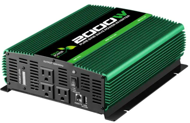
Nature POWER Power Inverter
Thank you for choosing a Nature Power Product
This product is designed for certain applications only. The distributor cannot be responsible for issues arising from modification. We strongly recommend this product not be modified and/or used for any application other than that for which it was designed. If you have a question relative to a particular application, do not use the product until you have first contacted the distributor to determine if it can or should be performed on the product.
For technical question please call 1-800-588-0590
PART LIST
| Reference | Part Description | Quantity |
| 1 | 3000W Inverter | 1 |
| 2 | Battery connecting cable red and black | 2 |
| 3 | Ground wire | 1 |
| 4 | User Manual | 1 |
WARNING
This product can expose you to chemicals, including Di (2-ethylhexyl) phthalate (DEHP) which is known to the State of California to cause cancer, birth defects or other reproductive harm. For more information, go to www.p65warnings.ca.gov
IMPORTANT SAFETY INSTRUCTIONS
- SAVE THESE INSTRUCTIONS.
This manual contains important safety and operating instructions for power inverter 3000W .This manual will show you how to use your inverter safely and effectively. Please read, understand and follow these instructions and precautions carefully. - Keep out of reach of children.
- Do not expose inverter to rain or snow.
- Use of an attachment not recommended or sold by the unit manufacturer may injury to persons.
- Do not disassemble the unit; take it to repair is required.
- To reduce risk of electric shock, unplug unit from outlet before attempting any maintenance or cleaning. Turning off controls will not reduce this risk.
- For the most effective use, place the power inverter on a flat surface.
- Do not place the inverter on or near heating vents, radiators or other sources
- Do not place the inverter in direct sunlight. The ideal air temperature for operation is between 50° and 80°F.
- Only connect the power inverter to a 12V battery or power supply. Do not attempt to connect the inverter to any other power source, including an AC power source. Connecting to a 6V or 16V battery will cause damage to the inverter.
- Do not use the inverter with a product that draws a higher wattage than the inverter can provide, as this may cause damage to the inverter and product.
FEATURES
- ON/OFF rocker switch
- LED indicator
Green indicates Power ON
Red indicates Overload/Interruption in power - 12 Volt power cord
- 120V standard AC outlets (4)
- USB port(s) – 5V, 2.0A
- High-speed cooling fan(2)
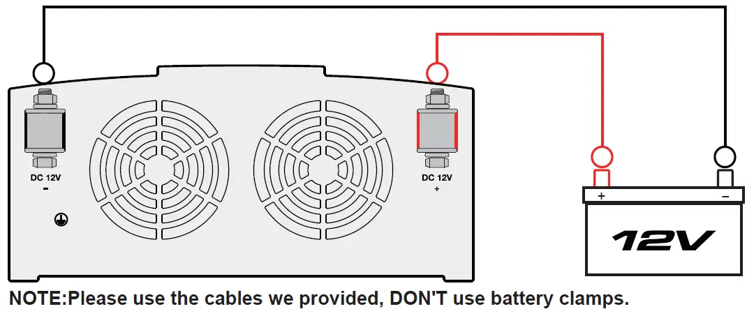
To keep the inverter cool, the fan turn on depend on temperature in the inverter. The fans do not run when the inverter is turned off. - Positive Battery Cable Terminal (Red)
- Negative Battery Cable Terminal (Black)
CONNECTING INVERTER CABLES
The inverter and power source must be in the OFF mode.
IMPORTANT: Make sure to connect your inverter only to a 12 volt power supply. To avoid electrical shock, it is necessary to ground the inverter as well as the device powering it. The inverter should be grounded, using a 15 AWG copper wire (included).
NOTE: Do not turn on the inverter or the power source until the inverter and the power source are grounded.
TO GROUND THE INVERTER
- Turn off and disconnect the inverter.
- Locate the chassis ground screw on the back of the inverter.
- Remove the outer nut and loosen the first locking washer.
- Attach the grounding wire’s ring connector to the ground terminal of the inverter.
- Tighten the locking washer securely. Then, replace the other nut and tighten it securely.
- Attach the other end of the wire to a properly grounded location:
Vehicle: Connect to the chassis, unpainted frame part, or engine block of the vehicle.
Fixed location: Connect to a ground rod or other appropriately rated ground.
CONNECTING INVERTER CABLES TO THE INVERTER
- Locate the Positive and Negative terminals on the inverter.
- From the POSITIVE (RED) and the NEGATIVE (BLACK) terminals.
- Place the POSITIVE (RED) ring connector onto the POSITIVE (RED) inverter terminal. Place the NEGATIVE (BLACK) ring connector onto the NEGATIVE (BLACK) inverter terminal.
- Place a flat washer and split lock on top of each ring connector. Put a nut over these and tighten.

OPERATING INSTRUCTIONS
After mounting and connecting your Inverter according to the instructions in this manual, use the ON/OFF/REMOTE switch to choose the Inverter’s operating mode.
ON: When you set the switch to the ON (I) position, the Inverter provides AC power to connected equipment by converting DC power from your vehicle’s battery. The green LED will illuminate to indicate it is working.
OFF: Set the switch to the OFF (O) position to shut down the Inverter completely. Doing this will prevent it from drawing power from your vehicle’s battery. Also set the switch to the OFF position to reset the Inverter if it has shut down due to low battery, overload or other critical condition.
REMOTE: When you set the switch to the REMOTE (II) position, the Inverter provides AC power to connected equipment by converting DC power from your vehicle’s battery.The green LED will illuminate to indicate it is working.You can then power the inverter ON/OFF from a remote location via the included remote. This remote switch can be mounted in the vehicle or a permanent mount application. The green LED on the remote will illuminate to indicate the inverter is in the ON operating mode.
- Connect the Inverter (see CONNECT-ING INVERTER CABLES).
- Switch the Inverter’s ON/OFF switch to the ON (I) position. If you are using the included remote panel, set the switch to the REMOTE (II) position and press the ON button on the remote panel.
- The green LED indicator will illuminate on the unit or remote panel (If installed), indicating the Inverter is receiving power.
- Switch the Inverter’s ON/OFF/REMOTE switch to the OFF (O) position. The green LED may flash briefly and/or the internal speaker may beep briefly. This is normal.
- Make sure the device(s) to be operated is turned OFF.
- Plug the device(s) into the Inverter’s AC outlet(s).
POWER SOURCE
Your average automobile battery at full charge will provide an ample power supply to the inverter when the engine is on. Keep the car running at all times when using the inverter. The actual length of time the inverter will function depends on the age and condition of the battery and the power demand being placed by the device being operated with the inverter.
When possible, recharge your batteries when they are not more than 50%discharged. This gives the batteries a much longer life cycle than recharging when they are more deeply discharged. - Switch the inverter’s ON/OFF/REMOTE switch to the ON (I) or REMOTE (II) positions. If using the remote position, connect the cable connector to the RJ11 jack on the unit labeled REMOTE and press the ON/OFF momentary switch to power the inverter.
- Turn the device(s) on.
- To disconnect, reverse the above procedure.
The power inverter has a battery low voltage shutdown at 10V±0.5V DC. With moderate to heavy loads, this will protect against over-discharging the battery. If the inverter is running only light loads it is advisable to recharge before the inverter low voltage shutdown point is reached.
IMPORTANT: The inverter draws low amperage from the battery with the main ON/OFF switch turned on and no load connected. To prevent battery discharge, turn the inverter off when you are not using it.
LED INDICATOR AND SHUTDOWN PROTECTION
The Green LED lights automatically when the inverter is plugged into a 12 volt
DC power source and is turned on. The Red LED lights, the alarm sounds and the inverter automatically turns itself off under the following conditions:
- When the power input from the vehicle’s battery drops to approximately 10.5 volts, the low voltage alarm will sound. When the voltage goes down below 10 VDC, the inverter shuts off. Recharge or replace the battery.
- When the power input from the vehicle’s battery exceeds 16 volts, high voltage protection occurs.
- The continuous load demand from the equipment or device being operated exceeds the continuous load rating of the inverter. Use a higher capacity inverter or lower rated device.
- The thermal resistor exceeds 80° C (176° F.) Allow the inverter to cool.
RESET: To reset after shutdown occurs, switch the inverter’s ON/OFF switch to the OFF (O) position. Check the source of the problem and correct. Switch the inverter’s ON/OFF switch to the ON (I) position.
IF THE INVERTER’S FUSE BLOWS
Your power inverter is fitted with fuses, which should not have to be replaced under normal operating conditions. A blown fuse is usually caused by reverse polarity or a short circuit within the device or equipment being operated.
If a fuse does blow, take the inverter to a technician for repair.
MAINTENANCE AND STORAGE INSTRUCTIONS
- Before each use, ensure that all of the inverter’s components are in place and in good working condition.
- After use and before performing maintenance, unplug and disconnect the inverter.
- Use a clean, dry cloth to wipe external surfaces of the inverter’s case.
- Servicing does not require opening the unit, as there are no user-serviceable parts. All servicing should be performed
- Store inside, in a cool, dry place, out of the reach of children.
- Recycle or properly dispose of internal electrical components.
TROUBLESHOOTING
| PROBLEM | POSSIBLE CAUSE | SOLUTION |
| Low or no output voltage. | Poor contact at terminals OVP/OLP.
Using incorrect type of voltmeter to test output voltage. |
Disconnect and reconnect the 12V connections.
Use a true RMS reading meter. |
| Red LED is lit. | The battery voltage is below 10 volts. The equipment being operated is drawing too much power. The inverter is too hot (thermal shutdown). |
Recharge or replace the battery.
Use a higher capacity inverter or decrease the load or device on the inverter Allow inverter to cool. Check for adequate ventilation. Reduce the load on the inverter to the rated continuous power output. |
| Device does not operate properly to the inverter. | The inverter may not have the required capacity to operate the device. | Turn the inverter switch OFF and ON, to reset the inverter. |
SPECIFICATIONS
Nominal input voltage 12.8-13.2 VDC
Nominal output voltage 115±10% VAC
Output frequency . 60±3 Hz
Operating input voltage. 10.0-15.0 VDC
Continuous output power Up to 3000 W
Surge output power. 6000 W
Waveform Modified sine wave
Efficiency (typical) 86%
Typical No Load Current (at nominal input voltage) .0.5 ADC
Input overvoltage shutdown . .15.5±0.5 VDC
Input under voltage alarm 10.5±0.5 VDC
Input low voltage shutdown. 10.0±0.5 VDC
Output power overload shutdown level 3400±400
W Input fuse 8×40 A
AC receptacles. .Four, NEMA 5-15 USA
USB port Two, 5V 2A
Battery cables 6AWG, 4×39.3 in
Ground wire . 15AWG, 1×39.3 in
LIMITED WARRANTY
Nature Power warrants our products to the original purchaser that this product is free from defects in materials and workmanship for the period of one year from date of purchase. In the case of product defect, contact Nature Power customer service to receive troubleshooting. If defective part or unit should be returned, a Return Authorization Number must be issued by Nature Power and the defective part or unit should be returned to the authorized location at the purchasers’ expense. A dated proof of purchase is required to receive warranty service. Once received at authorized location and defect proves to be the result of defective material and workmanship, the defective part or unit will be replaced at warrantors’ option and returned to the original purchaser at warrantors’ expense. No refunds will be granted by the warrantor, In the event of buyer’s remorse, please contact your point of purchase and adhere to their return policy.
Please contact Nature Power Products to acquire more information:
1-800-588-0590
[email protected]
www.naturepowerproducts.com
![]()
User Manual
 WARNING: Read and understand all instructions, warnings, and cautions before using this product. Failure to follow the instructions, warnings, and cautions may result in serious personal injury and/ or property damage.
Item #22260
SAVE THIS INSTRUCTION
GENERAL SAFETY RULES
Save the receipt and these instructions. It is important that you read the entire manual to become familiar with this product before you begin using it.
This product is designed for certain applications only. The distributor cannot be responsible for issues arising from modification. We strongly recommend this product not be modified and/or used for any application other than that for which it was designed. If you have any questions relative to a particular application, DO NOT use the product until you have first contacted the distributor to determine if it can or should be performed on the product.
For technical questions please call 1400-588-0590.
![]() CAUTION: Do not allow persons to operate or assemble this Solar Light until they have read this manual and have developed a thorough understanding of how the Solar Light works.
CAUTION: Do not allow persons to operate or assemble this Solar Light until they have read this manual and have developed a thorough understanding of how the Solar Light works.
![]() WARNING: The warnings, cautions, and instructions discussed in this instruction manual cannot cover all possible conditions or situations that could occur. It must be understood by the operator that common sense and caution are factors that cannot be built into this product but must be supplied by the operator.
WARNING: The warnings, cautions, and instructions discussed in this instruction manual cannot cover all possible conditions or situations that could occur. It must be understood by the operator that common sense and caution are factors that cannot be built into this product but must be supplied by the operator.
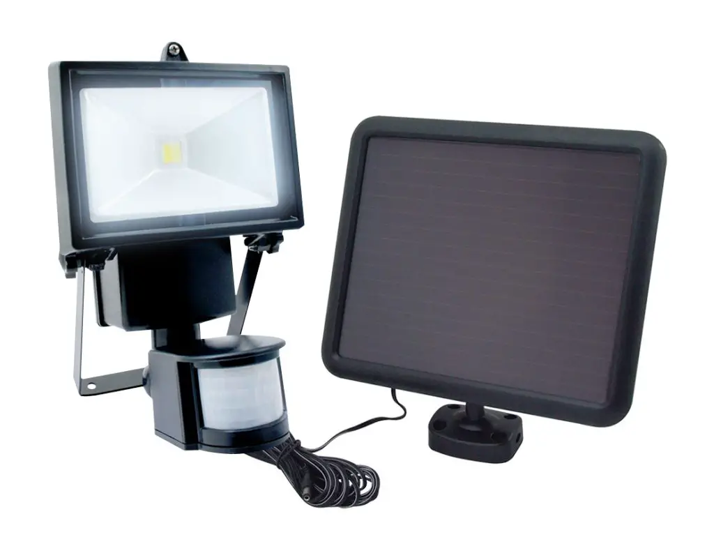
FEATURES
Your COB Security Light is the perfect system for the following:
- Entrance
- Garage
- Porch
- Eaves
- Emergency
| PARTS LIST | ||
| Part*, | Description | Qty. |
| 1 | Lamp | 1 |
| 2 | Solar Panel (5m Wire) | 1 |
| 3 | Screws and Anchors | 1 |
| 4 | Mounting Bracket | 1 |
| 5 | Manual | 1 |
USE AND CARE
- Do not modify the Solar Light in any way. Unauthorized modification may impair the function and/or safety and could affect the life of the equipment. There are specific applications for which the Solar Light was designed.
- Always check for damaged or worn-out parts before using the Solar Light. Broken parts will affect the Solar Light operation. Replace or repair damaged or worn parts immediately.
- Store idle Solar Light. When Solar Light is not in use, store it in a secure place out of the reach of children. Inspect it for good working condition prior to storage and before re-use.
ASSEMBLY
1. Lamp Unit Installation
- Mounting your light requires a screwdriver, pencil, and (in some circumstances) a power drill.
- Place the mounting bracket on the surface you wish to mount to.
- Mark with a pencil the position of the mounting bracket screw holes. This will enable you to pre-drill your screw holes.
- Once the mounting bracket is installed, ensuring all screws are tight, you are ready to position your COB Security Light
- Carefully route the wire from the solar panel to the lamp and plug it into the power socket.
- Adjust the motion sensor to your desired position. Your COB Security Light is now installed and ready to charge.
Note: Lamp unit should be mounted 6.5 9.8ft from the ground to ensure motion detection is optimized.
2. Solar Panel Wall or Roof Mounted Installation
- Choose an area that receives the maximum amount of sunlight possible
- Use the holes located on the solar panel mounting bracket to mark the mounting surface for installation
- Set the bracket on the surface you have chosen and secure it in place with the screws and anchors provided.
- Adjust the angle of the Solar Panel to ensure it receives optimum sunlight.
Note: The Solar Panel is equipped with a 5 ft. wire. The maximum distance between the lamp unit and solar panel can be 5 ft.
ASSEMBLY DIAGRAM
PARTS LIST AND ASSEMBLY DIAGRAM
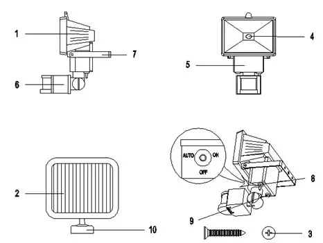
| Part | Description | Part | Description |
| 1 | Lamp | 8 | ON OFF AUTO Switch |
| 2 | Solar Panel (5m wire) | 9 | Battery Housing outlet |
| 3 | Expansion screw | 10 | Solar Panel Mounting Bracket |
| 4 | 5W LED | 11 | LUX Adjusting Knob |
| 5 | Battery Housing | 12 | SENS Adjusting Knob |
| 6 | Motion Detector Head | 13 | TIME Adjusting Knob |
| 7 | “U” shaped Mounting Plate | 14 | NI-I-EM battery (not shown) |
OPERATION
- Before the Solar Motion Light can operate to its full capacity, the Solar Panel needs to be in sunlight for 3 days to fully charge the included battery. Charging should be done with the unit in the “OFF” position.
- Located at the bottom of the Battery Housing (5) there is a switch with three positions:
- Turn the switch to the “AUTO” position, the light will turn on automatically at night when motion is detected by the Motion Detector Head (6).
- Turn the switch to the “ON” position, the light can be used as a standard light for constant illumination.
- Turn the switch to the “OFF” position, the light will remain off and will not detect any movement.
HOW TO USE CONTROL DIALS
The Solar Motion Light has 3 different control dials which control the light’s duration, sensitivity to light, and sensitivity to motion.
LUX (LIGHT LEVEL)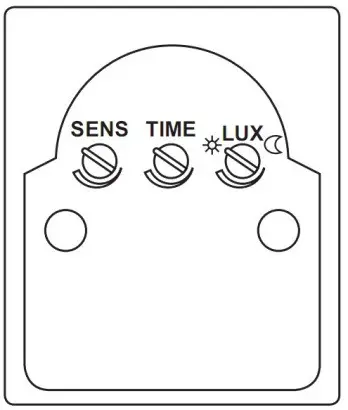
- The LUX Adjusting dial (9) tells the sensor the level of darkness that must be reached before the light turns on.
- If set to the maximum
 level, the light will go on in daylight.
 - If set to the minimum setting
 the sensor will only trigger the light to turn on at dusk or when it is dark out. This is the ideal position for general usage.
TIME
- The TIME Adjusting dial (11) sets the duration of illumination time.
- The TIME is adjustable from 8 seconds to 2 minutes. Rotating the dial clockwise will increase the illumination time.
SENS (SENSITIVITY
This determines the range of motion detection:
- Minimum position — Low Range.
- Mid Position – Normal setting.
- Maximum position – Maximum range.
LOCATION OF SOLAR LIGHT
For best results, please locate the Solar Panel from your COB Solar Light in a position where it can absorb direct sunlight on the solar panel, and generally tree from cover and shade.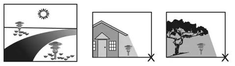
TROUBLESHOOTING
If the Solar Motion Light does not Illuminate when movement in front of the sensor is obvious, please observe the following:
- Ensure the solar panel is in a location where it will receive maximum sunlight during daytime hours.
- Ensure the lamp head is away from other light sources. Other light sources at night will prevent the unit from turning on.
- Ensure the switch is set to the “AUTO” or “ON’ position.
- Check batteries are installed correctly.
- Allow the solar panel to charge the batteries in direct sunlight for 3 days with the switch in the “OFF” position.
- Replace Batteries. Rechargeable batteries may last up to 600 charges. For best performance replace batteries every 12 months.
BATTERY REPLACEMENT
- The Battery Pack is located in the Battery Housing (5).
- Turn the switch (7) to the “OFF” position. Remove the four screws from the Battery Housing (5). Separate the Battery Pack connector. Remove old Battery Pack. Replace only with identical rechargeable Battery Pack.
- Check correct polarity of battery replacement.
- Replace the cover of the Battery Housing (5). Secure it with the four screws.
MAINTENANCE
Maintain your Solar light. It is recommended that the general condition of any Solar Light be examined before it is used. Clean the solar module with a damp towel to ensure the optimum performance of the Solar Light. Do not use any type of solvent for cleaning and be careful not to put too much pressure on the module while cleaning.
LIMITED WARRANTY
Nature Power warrants our products to the original purchaser that this product is free from defects in materials and workmanship for the period of one year from the date of purchase. In the case of a product defect, contact Nature Power customer service to receive troubleshooting. If a defective part or unit should be returned, a Return Authorization Number must be issued by Nature Power and the defective part or unit should be returned to the authorized location at the purchasers’ expense. A dated proof of purchase is required to receive warranty service. Once received at authorized location and defect proves to be the result of defective material and workmanship, the defective part or unit will be replaced at warrantors’ option and returned to the original purchaser at warrantors’ expense. No refunds will be granted by the warrantor, in the event of buyer’s remorse please contact your point of purchase within and in adherence to their return policy. Refunds are granted at the retailers’ discretion.
Dated proof of purchase is required
![]()
Please contact Nature Power Products to acquire more information:
1-800-588-0590
[email protected]
www.naturepowerproducts.com
Made in China
]]>