ozito 18V Lithium Ion Battery and Charger Instruction Manual

PXBP-200
DESCRIPTION OF SYMBOLS
 |
Volts |  |
Hertz |
 |
Alternating Current |  |
Watts |
 |
Direct Current |  |
Amp Hour |
 |
Milliamperes |  |
Warning |
 |
Lithium Ion Battery |  |
Do not store or use battery in temperatures exceeding 50°C |
 |
Recycle Battery |  |
Do not put in the rubbish |
 |
Do not incinerate |  |
Do not get battery wet |
 |
Regulatory Compliance Mark (RCM) | 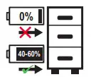 |
Do not store battery when the charge is low; store between 40-60%. |
CARING FOR THE ENVIRONMENT
 Power tools that are no longer usable should not be disposed of with household waste but in an environmentally friendly way. Please recycle where facilities exist. Check with your local council authority for recycling advice.
 Recycling packaging reduces the need for landfill and raw materials.
Reuse of recycled material decreases pollution in the environment.
Please recycle packaging where facilities exist. Check with your local council authority for recycling advice.
SPECIFICATIONS
Input: 18V
Battery Capacity: 2.0Ah Li-ion
Power Consumption: 36Wh
Weight: 0.40kg
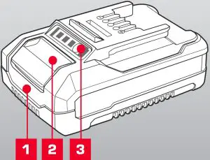
- Battery
- Battery Release Button
- Charge Indicator Button
BATTERY SAFETY WARNINGS
 THIS MANUAL CONTAINS IMPORTANT SAFETY AND OPERATING INSTRUCTIONS FOR YOUR BATTERY.
- Before using the charger read all instructions and cautionary markings on the charger, battery pack and the product using the battery pack.
- This charger is not intended for any uses other than charging Ozito Power X Change rechargeable batteries. Any other use may result in risk of fire, electric shock or electrocution.
- Do not place any object on top of the charger or place the charger on a soft surface that may result in excessive internal heat. Place the charger in a position away from any heat source.
- To reduce risk of damage to the electric plug and cord, pull by the plug rather than the cord when disconnecting the charger.
- Make sure the cord is located so that it will not be stepped on, tripped over, or otherwise subjected to damage or stress.
- An extension cord should not be used unless absolutely necessary. Use of an improper extension cord could result in the risk of fire, electric shock or electrocution.
- Do not operate the charger if it has received a sharp blow, been dropped or otherwise damaged in any way. Have it checked by an electrician or power tool repairer.
- Do not disassemble charger. Take it to an electrician or power tool repairer when service or repair is required. Incorrect reassembly may result in a risk of electric shock, electrocution or fire.
- To reduce risk of electric shock, unplug the charger from the outlet before attempting any cleaning. Removing the battery pack will not reduce this risk.
- Never attempt to connect 2 chargers together.
- The charger is designed to operate on standard household electrical power (240 volts). Do not attempt to use it on any other voltage!
- The battery pack is not fully charged out of the carton. First read the safety instructions and then follow the charging notes and procedures.
- DO NOT STORE OR USE the battery pack in locations where the temperature may reach below 0ºC or exceed 50ºC (such as inside sheds or metal buildings in summer). This is important and will prevent damage to the battery pack.
- Do not incinerate the battery pack even if it is seriously damaged or is completely worn out. The battery can explode in a fire.
- Never attempt to open the battery pack for any reason. If the plastic housing of the battery pack breaks or cracks, immediately discontinue use and do not recharge.
- During charging, the battery must be placed in a well ventilated area.
ELECTRICAL SAFETY
WARNING! When using mains-powered tools, basic safety precautions,
including the following, should always be followed to reduce risk of fire, electric shock, personal injury and material damage.
Read the whole manual carefully and make sure you know how to switch the tool off in an emergency, before operating the tool.
Save these instructions and other documents supplied with this tool for future reference.
Note: The supply of 230V and 240V on Ozito tools are interchangeable for Australia and New Zealand.
 This tools charger is double insulated, therefore no earth wire is required.
If the supply cord is damaged, it must be replaced by the manufacturer, its service agent or similarly qualified persons in order to avoid hazard.
Note: Double insulation does not take the place of normal safety precautions when operating this tool. The insulation system is for added protection against injury resulting from a possible electrical insulation failure within the tool.
Using an Extension Lead
Always use an approved extension lead suitable for the power input of this tool. Before use, inspect the extension lead for signs of damage, wear and ageing. Replace the extension lead if damaged or defective.
When using an extension lead on a reel, always unwind the lead completely. Use of an extension lead not suitable for the power input of the tool or which is damaged or defective may result in a risk of fire and electric shock.
To reduce the risk of electric shock, we recommend the use of a residual current device (rated 30mA or less).
This appliance is not intended for use by persons (including children) with reduced physical, sensory or mental capabilities, or lack of experience and knowledge, unless they have been given supervision or instruction concerning use of the appliance by a person responsible for their safety.
Children should be supervised to ensure that they do not play with the appliance.
OPERATION
Only use the battery pack with Ozito Power X Change 18V cordless products.
CHARGING YOUR LITHIUM ION BATTERY
This battery has been shipped in a low charge condition, and requires charging prior to use. Allow several cycles of charging and discharging (through use with a compatible tool) for the battery to reach its optimum performance / runtime.
This battery is compatible with chargers from the 18V Ozito Power X Change range available through your local Bunnings Warehouse. Product availability may differ.
Only use the battery pack with Ozito Power X Change 18V cordless products.
- Insert the power plug of the charger into the mains socket outlet. The green LED will begin to flash when properly connected to power supply.
- Insert the battery pack into the battery charger .
- Remove battery from the charger once fully charged. Disconnect the charger from the power supply.
Note: The battery pack can become a little warm during the charging. This is normal.
If the battery pack fails to charge, check
if there is voltage at the socket outlet that the battery and charger are properly connected.
If the battery pack still fails to charge, please contact our customer service center.
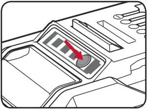
BATTERY CHARGE INDICATOR
The purchased battery is equipped with a battery charge indicator to show the state of the battery charge.
Press the charge indicator button and look to see which LED lights.
- Battery requires immediate charging
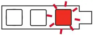
- Low state of charge, requires charging soon.
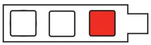
- Mid state of charge
- Full state of charge.

BATTERY PROTECTION SYSTEM
The tool is equipped with a battery protection system, which helps to ensure longevity of the battery.
The output power automatically cuts off during operation when the tool and/or battery are placed under the following situations:
- When the tool is overloaded
If this occurs, release the trigger switch and remove causes of overload, then pull the switch trigger again to restart. - When the remaining battery capacity becomes low
Recharge the battery pack.
Note: The battery protection system does not in any way damage the tool.
Note: The indicated capacity may be lower than the actual level during use or immediately after using the tool.
WARRANTY
IN ORDER TO MAKE A CLAIM UNDER THIS WARRANTY YOU MUST RETURN THE PRODUCT TO YOUR NEAREST BUNNINGS WAREHOUSE WITH YOUR BUNNINGS REGISTER RECEIPT. PRIOR TO RETURNING YOUR PRODUCT FOR WARRANTY PLEASE TELEPHONE OUR CUSTOMER SERVICE HELPLINE:
Australia 1800 069 486
New Zealand 0508 069 486
TO ENSURE A SPEEDY RESPONSE PLEASE HAVE THE MODEL NUMBER AND DATE OF PURCHASE AVAILABLE. A CUSTOMER SERVICE REPRESENTATIVE WILL TAKE YOUR CALL AND ANSWER ANY QUESTIONS YOU MAY HAVE RELATING TO THE WARRANTY POLICY OR PROCEDURE.
The benefits provided under this warranty are in addition to other rights and remedies which are available to you at law.
Our goods come with guarantees that cannot be excluded at law. You are entitled to a replacement or refund for a major failure and for compensation for any other reasonably foreseeable loss or damage. You are also entitled to have the goods repaired or replaced if the goods fail to be of acceptable quality and the failure does not amount to a major failure.
Generally you will be responsible for all costs associated with a claim under this warranty, however, where you have suffered any additional direct loss as a result of a defective product you may be able to claim such expenses by contacting our customer service helpline above.
36 MONTH REPLACEMENT WARRANTY

Your product is guaranteed for a period of 36 months from the original date of purchase and is intended for DIY (Do It Yourself) use only. If a product is defective it will be replaced in accordance with the terms of this warranty. Warranty excludes consumable parts.
WARNING
The following actions will result in the warranty being void.
- If the tool has been operated on a supply voltage other than that specified on the tool.
- If the tool shows signs of damage or defects caused by or resulting from abuse, accidents or alterations.
- Failure to perform maintenance as set out within the instruction manual.
- If the tool is disassembled or tampered with in any way.
ONLINE MANUAL
 Scan this QR Code with your mobile device to take you to the online manual.
OZITO Australia/New Zealand (Head Office)
1-23 Letcon Drive, Bangholme, Victoria, Australia 3175.
PXBP-400
DESCRIPTION OF SYMBOLS
| |
Volts | |
Hertz |
|
Alternating Current | |
Watts |
|
Direct Current | |
Amp Hour |
|
Milliamperes | |
Warning |
| |
Lithium Ion Battery | |
Do not store or use battery in temperatures exceeding 50°C |
|
Recycle Battery | |
Do not put in the rubbish |
|
Do not incinerate | |
Do not get battery wet |
|
Regulatory Compliance Mark (RCM) | |
Do not store battery when the charge is low; store between 40-60%. |
CARING FOR THE ENVIRONMENT
Power tools that are no longer usable should not be disposed of with household waste but in an environmentally friendly way. Please recycle where facilities exist. Check with your local council authority for recycling advice.
Recycling packaging reduces the need for landfill and raw materials.
Reuse of recycled material decreases pollution in the environment.
Please recycle packaging where facilities exist. Check with your local council authority for recycling advice.
SPECIFICATIONS
Input: 18V
Battery Capacity: 4.0Ah Li-ion
Power Consumption: 72W
Weight: 0.65kg
- Battery
- Battery Release Button
- Charge Indicator Button
BATTERY & CHARGER SAFETY WARNINGS
Before using the charger or battery read all instructions and cautionary markings on the charger, battery pack and the product using the battery pack. Do not lose these safety instructions.
Battery Warnings
- The battery pack is not fully charged out of the carton. First read the safety instructions and then follow the charging notes and procedures.
- For optimum battery performance avoid low discharge cycles. Charge the battery pack frequently.
- Use and store the battery pack in dry conditions with low humidity between 0-50°C, ideally at 15°C. Avoid exposing battery pack and charger to direct sunlight.
- Do not keep battery pack in places where temperatures are liable to reach over 50°C, such as in a car, metal shed or similar that is in direct sunlight.
- Do not ignite the battery pack or expose it to fire. There is a risk of explosion!
- Do not exhaustively discharge batteries. Exhaustive discharge will damage the battery cells. The most common cause of exhaustive discharge is long term storage and continued use of low-charge batteries. Always store the battery with some charge. Charge the batteries every 2-3 months to restore charge. Stop working as soon as the performance of the battery falls noticeably or the electronic protection system triggers.
- Protect batteries and the tool from overloads. Overloads will quickly result in overheating and cell damage inside the battery housing without this overheating being apparent externally.
- Avoid damage and shocks. Do not use batteries which have been dropped from a height of more than one meter or strong external impact, even if the housing of the battery pack appears to be undamaged. The battery cells inside the battery may have suffered serious damage.
- If the battery pack suffers overloading and overheating, the integrated protective cut-off will switch off the equipment. Do not press the ON/OFF switch on the tool if the protective cut-off has actuated. This may damage the battery pack. Allow the battery to cool to room temperature before use.
- Use only original battery packs. The use of other batteries may result in injuries, explosion and a fire risk.
- Protect your rechargeable battery against moisture, rain and high humidity. Moisture, rain and high humidity can cause dangerous cell damage. Never charge or use batteries which have been exposed to moisture, rain or high humidity.
- Never attempt to open the battery pack for any reason. If the plastic housing of the battery pack is damaged, do not use the battery.
- When battery pack is not in use, keep it away from other metal objects, like paper clips, coins, keys, nails, screws or other small metal objects, that can make a connection from one terminal to another. Shorting the battery terminals together may cause burns or a fire.
- Under abusive conditions, liquid may be ejected from the battery; avoid contact. If accidental contact occurs, flush with water and seek medical help immediately. Liquid ejected from the battery may cause irritation or burns.
- Do not use a battery pack or tool that is damaged or modified. Damaged or modified batteries may exhibit unpredictable behaviour resulting in fire, explosion or risk of injury.
- Do not expose a battery pack or tool to fire or excessive temperature. Exposure to fire or temperature above 130°C may cause explosion.
- Never service damaged battery packs. Service of battery packs should only be performed by the manufacturer.
- Do not disassemble Battery. This may result in a risk of electric shock, electrocution or fire.
Charger Warnings - Please check the data marked on the rating plate of the battery charger. Ensure to only connect the battery charger
to a power supply with the voltage marked on the rating plate. - Protect the battery charger and its cable from damage and sharp edges. Have damaged cables repaired by an authorised service agent before use.
- Keep the battery charger, batteries and the cordless tool out of children’s reach.
- Do not use damaged battery chargers.
- Do not use the supplied battery charger to charge other cordless tools. Only charge Ozito Power X Change rechargeable batteries with an Ozito Power X Change Charger.
- The battery pack may become warm during use. Allow the battery pack to cool to room temperature before commencing with the charging.
- Do not over-charge batteries. Do not exceed the maximum charging times. These charging times only apply to discharged batteries. Frequent insertion of a charged or partly charged battery pack will result in over charging and cell damage. Do not leave fully charged batteries in the charger.
- Charge the battery pack in dry conditions with low humidity between 10 40°C. Avoid exposing battery pack and charger to direct sunlight.
- Do not use batteries which have suffered deformation during the charging process or shows any other signs of abnormalities including, excessive curvature of the housing, gassing, hissing or cracking.
- Never fully discharge the battery pack. A complete discharge of the battery pack will lead to premature ageing of the battery cells.
- Never charge the batteries unsupervised.
- Do not cover or place any object on top of the charger, place the charger away from heat sources.
- To reduce risk of damage to the electric plug and cord, pull by the plug rather than the cord when disconnecting the charger.
- Make sure the cord is located so that it will not be stepped on, tripped over, or otherwise subjected to damage or stress.
- An extension cord should not be used unless necessary. Use of an improper extension cord could result in the risk of fire, electric shock or electrocution.
- Do not disassemble charger. This may result in a risk of electric shock, electrocution or fire.
- To reduce risk of electric shock, unplug the charger from the outlet before attempting any cleaning. Removing the battery pack will not reduce this risk.
- Do not use the cordless tool or the battery charger near vapours and inflammable liquids.
ELECTRICAL SAFETY
WARNING! When using mains-powered tools, basic safety precautions,
including the following, should always be followed to reduce risk of fire, electric shock, personal injury and material damage.
Read the whole manual carefully and make sure you know how to switch the tool off in an emergency, before operating the tool.
Save these instructions and other documents supplied with this tool for future reference.
Note: The supply of 230V and 240V on Ozito tools are interchangeable for Australia and New Zealand.
This tools charger is double insulated, therefore no earth wire is required.
If the supply cord is damaged, it must be replaced by the manufacturer, its service agent or similarly qualified persons in order to avoid hazard.
Note: Double insulation does not take the place of normal safety precautions when operating this tool. The insulation system is for added protection against injury resulting from a possible electrical insulation failure within the tool.
Using an Extension Lead
Always use an approved extension lead suitable for the power input of this tool. Before use, inspect the extension lead for signs of damage, wear and ageing. Replace the extension lead if damaged or defective.
When using an extension lead on a reel, always unwind the lead completely. Use of an extension lead not suitable for the power input of the tool or which is damaged or defective may result in a risk of fire and electric shock.
To reduce the risk of electric shock, we recommend the use of a residual current device (rated 30mA or less).
This appliance is not intended for use by persons (including children) with reduced physical, sensory or mental capabilities, or lack of experience and knowledge, unless they have been given supervision or instruction concerning use of the appliance by a person responsible for their safety.
Children should be supervised to ensure that they do not play with the appliance.
OPERATION
Only use the battery pack with Ozito Power X Change 18V cordless products.
CHARGING YOUR LITHIUM ION BATTERY
This battery has been shipped in a low charge condition, and requires charging prior to use. Allow several cycles of charging and discharging (through use with a compatible tool) for the battery to reach its optimum performance / runtime.
This battery is compatible with chargers from the 18V Ozito Power X Change range available through your local Bunnings Warehouse. Product availability may differ.
- Insert the power plug of the charger into the mains socket outlet. The green LED will begin to flash when properly connected to power supply.
- Insert the battery pack into the battery charger .
- Remove battery from the charger once fully charged. Disconnect the charger from the power supply.
Note: The battery pack can become a little warm during the charging. This is normal.
If the battery pack fails to charge, check
if there is voltage at the socket outlet that the battery and charger are properly connected.
If the battery pack still fails to charge, please contact our customer service center.
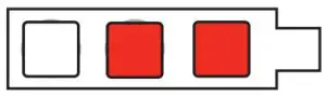
BATTERY CHARGE INDICATOR
The purchased battery is equipped with a battery charge indicator to show the state of the battery charge.
Press the charge indicator button and look to see which LED lights.
- Battery requires immediate charging
- Low state of charge, requires charging soon.
- Mid state of charge
- Full state of charge.
Note: The battery needs to be removed from the tool to check the state of charge.
BATTERY PROTECTION SYSTEM
The tool is equipped with a battery protection system, which helps to ensure longevity of the battery.
The output power automatically cuts off during operation when the tool and/or battery are placed under the following situations:
- When the tool is overloaded
If this occurs, release the trigger switch and remove causes of overload, then pull the switch trigger again to restart. - When the remaining battery capacity becomes low
Recharge the battery pack.
Note: The battery protection system does not in any way damage the tool.
Note: The indicated capacity may be lower than the actual level during use or immediately after using the tool.
WARRANTY
IN ORDER TO MAKE A CLAIM UNDER THIS WARRANTY YOU MUST RETURN THE PRODUCT TO YOUR NEAREST BUNNINGS WAREHOUSE WITH YOUR BUNNINGS REGISTER RECEIPT. PRIOR TO RETURNING YOUR PRODUCT FOR WARRANTY PLEASE TELEPHONE OUR CUSTOMER SERVICE HELPLINE:
Australia 1800 069 486
New Zealand 0508 069 486
TO ENSURE A SPEEDY RESPONSE PLEASE HAVE THE MODEL NUMBER AND DATE OF PURCHASE AVAILABLE. A CUSTOMER SERVICE REPRESENTATIVE WILL TAKE YOUR CALL AND ANSWER ANY QUESTIONS YOU MAY HAVE RELATING TO THE WARRANTY POLICY OR PROCEDURE.
The benefits provided under this warranty are in addition to other rights and remedies which are available to you at law.
Our goods come with guarantees that cannot be excluded at law. You are entitled to a replacement or refund for a major failure and for compensation for any other reasonably foreseeable loss or damage. You are also entitled to have the goods repaired or replaced if the goods fail to be of acceptable quality and the failure does not amount to a major failure.
Generally you will be responsible for all costs associated with a claim under this warranty, however, where you have suffered any additional direct loss as a result of a defective product you may be able to claim such expenses by contacting our customer service helpline above.
36 MONTH REPLACEMENT WARRANTY
Your product is guaranteed for a period of 36 months from the original date of purchase and is intended for DIY (Do It Yourself) use only. If a product is defective it will be replaced in accordance with the terms of this warranty. Warranty excludes consumable parts.
WARNING
The following actions will result in the warranty being void.
- If the tool has been operated on a supply voltage other than that specified on the tool.
- If the tool shows signs of damage or defects caused by or resulting from abuse, accidents or alterations.
- Failure to perform maintenance as set out within the instruction manual.
- If the tool is disassembled or tampered with in any way.
ONLINE MANUAL
 Scan this QR Code with your mobile device to take you to the online manual. OZIT
PXCG-030
DESCRIPTION OF SYMBOLS
|
Volts | |
Hertz |
 |
Amperes | |
Amp Hour |
 |
Read Instruction Manual | |
Double Insulated |
 |
Indoor Use Only | |
Do not dispose of in rubbish |
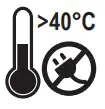 |
Do not charge battery in temperatures exceeding 40°C | |
Regulatory Compliance Mark (RCM) |
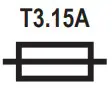 |
3.15A Slow Blow Fuse | |
Warning |
CARING FOR THE ENVIRONMENT
Recycling packaging reduces the need for landfill and raw materials.
Reuse of recycled material decreases pollution in the environment.
Please recycle packaging where facilities exist. Check with your local council authority for recycling advice.
SPECIFICATIONS
- Input: 200-250V ~AC 50-60Hz
- Output: 21V DC, 3A
- Power Consumption: 72W
- Battery Charge Time:
- 30Min – PXBP-150 (18V 1.5Ah)
- 40Min – PXBP-200 (18V 2.0Ah)
- 60Min – PXBP-300 (18V 3.0Ah)
- 75Min – PXBP-400 (18V 4.0Ah)
- 120Min – PXBP-520 (18V 5.2Ah)
- 100Min – PXUBP-520 (18V 5.2Ah Ultra)
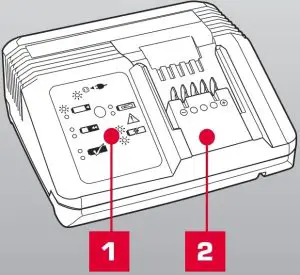
- Charging Unit
- Charging Unit LED
CHARGER SAFETY WARNINGS
THIS MANUAL CONTAINS IMPORTANT SAFETY AND OPERATING INSTRUCTIONS FOR YOUR CHARGER.
- Before using the charger read all instructions and cautionary markings on the charger, battery pack and the product using the battery pack.
- This charger is not intended for any uses other than charging Ozito Power X Change rechargeable batteries. Any other use may result in risk of fire, electric shock or electrocution.
- Do not place any object on top of the charger or place the charger on a soft surface that may result in excessive internal heat. Place the charger in a position away from any heat source.
- To reduce risk of damage to the electric plug and cord, pull by the plug rather than the cord when disconnecting the charger.
- Make sure the cord is located so that it will not be stepped on, tripped over, or otherwise subjected to damage or stress.
- An extension cord should not be used unless absolutely necessary. Use of an improper extension cord could result in the risk of fire, electric shock or electrocution.
- Do not operate the charger if it has received a sharp blow, been dropped or otherwise damaged in any way. Have it checked by an electrician or power tool repairer.
- Do not disassemble charger. Take it to an electrician or power tool repairer when service or repair is required. Incorrect reassembly may result in a risk of electric shock, electrocution or fire.
- To reduce risk of electric shock, unplug the charger from the outlet before attempting any cleaning. Removing the battery pack will not reduce this risk.
- Never attempt to connect 2 chargers together.
- The charger is designed to operate on standard household electrical power (240 volts). Do not attempt to use it on any other voltage!
- DO NOT USE the charger where the temperature may reach below 0° or exceed 40°C. If the battery pack is too hot or too cold charging will cease and begin automatically only when battery reaches correct charging temperature.
- Do not incinerate the battery pack even if it is seriously damaged or is completely worn out. The battery can explode in a fire.
- Never attempt to open the battery pack for any reason. If the plastic housing of the battery pack breaks or cracks, immediately discontinue use and do not recharge.
- During charging, the battery must be placed in va well ventilated area.
ELECTRICAL SAFETY
WARNING! When using mains-powered tools, basic safety precautions,
including the following, should always be followed to reduce risk of fire, electric shock, personal injury and material damage.
Read the whole manual carefully and make sure you know how to switch the tool off in an emergency, before operating the tool.
Save these instructions and other documents supplied with this tool for future reference.
Note: The supply of 230V and 240V on Ozito tools are interchangeable for Australia and New Zealand.
This tools charger is double insulated, therefore no earth wire is required.
If the supply cord is damaged, it must be replaced by the manufacturer, its service agent or similarly qualified persons in order to avoid hazard.
Note: Double insulation does not take the place of normal safety precautions when operating this tool. The insulation system is for added protection against injury resulting from a possible electrical insulation failure within the tool.
Using an Extension Lead
Always use an approved extension lead suitable for the power input of this tool. Before use, inspect the extension lead for signs of damage, wear and ageing. Replace the extension lead if damaged or defective.
When using an extension lead on a reel, always unwind the lead completely. Use of an extension lead not suitable for the power input of the tool or which is damaged or defective may result in a risk of fire and electric shock.
To reduce the risk of electric shock, we recommend the use of a residual current device (rated 30mA or less).
This appliance is not intended for use by persons (including children) with reduced physical, sensory or mental capabilities, or lack of experience and knowledge, unless they have been given supervision or instruction concerning use of the appliance by a person responsible for their safety.
Children should be supervised to ensure that they do not play with the appliance.
ONLINE MANUAL
 Scan this QR Code with your mobile device to take you to the online manual.
CHARGING A BATTERY
CAUTION: THE CHARGER SHOULD BE PROTECTED BY A RESIDUAL CURRENT DEVICE (RATED AT 30MA OR LESS).
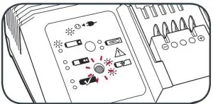
- Connect the charger to the power supply and the LED will flash green showing power is being supplied to the charger.
- Align and then slide the ribs on the battery into the recess in the charger.
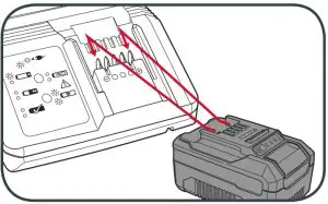
- The red LED will illuminate while the battery charges.
- The green LED will illuminate once the battery is charged.
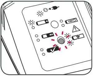
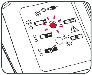
Charger LED Indicator Lights
| LED Indicator | Situation |
| GREEN (Flashing) | Stand By (no battery pack is inserted) |
| RED (Flashing) | Battery is charging (low charge) |
| RED (Illuminated) | Battery is fast charging (mid charge) |
| GREEN (Illuminated) | Battery is 85% – 100% charged and is ready for use |
| BOTH(Illuminated) | Battery pack is too hot or too cold (charging will begin automatically when battery reaches correct charging temperature). |
| BOTH (Flashing) | The battery is deffective, charging is no longer possible. Do not charge. Contact Ozito Customer Service. |
Mounting The Charging Unit On A Wall
The charging unit can be mounted to a wall or workbench.
The correct dimensions for drill holes can be found on the back of the charging unit; a template for the mounting hole locations can also be found on the Ozito website.
Note: When mounting on a wall you must use suitable screws, e.g.M3 pan-head screws, in order to prevent damage to the housing and risk of falling.
MAINTENANCE
- Disconnect the charger from power source before cleaning.
- Keep the charger in a dry place out of reach of children.
- If the enclosure of the charger requires cleaning, do not use solvents. Use a dry, soft cloth only to wipe down the surface. Never let any liquid get inside the charger; never immerse any part of the charger.
- There are no other parts inside the charger which require maintenance.Do not take the charger apart. If the charger is damaged, contact your supplier or the manufacturer.
WARRANTY
IN ORDER TO MAKE A CLAIM UNDER THIS WARRANTY YOU MUST RETURN THE PRODUCT TO YOUR NEAREST BUNNINGS WAREHOUSE WITH YOUR BUNNINGS REGISTER RECEIPT. PRIOR TO RETURNING YOUR PRODUCT FOR WARRANTY PLEASE TELEPHONE OUR CUSTOMER SERVICE HELPLINE:
Australia 1800 069 486
New Zealand 0508 069 486
TO ENSURE A SPEEDY RESPONSE PLEASE HAVE THE MODEL NUMBER AND DATE OF PURCHASE AVAILABLE. A CUSTOMER SERVICE REPRESENTATIVE WILL TAKE YOUR CALL AND ANSWER ANY QUESTIONS YOU MAY HAVE RELATING TO THE WARRANTY POLICY OR PROCEDURE.
The benefits provided under this warranty are in addition to other rights and remedies which are available to you at law.
Our goods come with guarantees that cannot be excluded at law. You are entitled to a replacement or refund for a major failure and for compensation for any other reasonably foreseeable loss or damage. You are also entitled to have the goods repaired or replaced if the goods fail to be of acceptable quality and the failure does not amount to a major failure.
Generally you will be responsible for all costs associated with a claim under this warranty, however, where you have suffered any additional direct loss as a result of a defective product you may be able to claim such expenses by contacting our customer service helpline above.
36 MONTH REPLACEMENT WARRANTY
Your product is guaranteed for a period of 36 months from the original date of purchase and is intended for DIY (Do It Yourself) use only. If a product is defective it will be replaced in accordance with the terms of this warranty. Warranty excludes consumable parts.
WARNING
The following actions will result in the warranty being void.
- If the tool has been operated on a supply voltage other than that specified on the tool.
- If the tool shows signs of damage or defects caused by or resulting from abuse, accidents or alterations.
- Failure to perform maintenance as set out within the instruction manual.
- If the tool is disassembled or tampered with in any way.
OZITO Australia/New Zealand (Head Office)
1-23 Letcon Drive, Bangholme, Victoria, Australia 3175.
MITRE SAW
210MM (8¼”)
INSTRUCTION MANUAL
STANDARD EQUIPMENT
| Compound Mitre Saw | 2 x Material Support Bars | 2 x Hex Keys & Dust Bag |
 |
 |
 |
SPECIFICATIONS
Mains Voltage: 220–240V ~ 50Hz
Motor Power: 1400W (S1);
1600W (S6 40%)
No Load Speed: 5,000/min
Blade: Ø210 x Ø16 x 2.8mm (48T)
Mitre Angle: 0-45° Left & Right
Bevel Angle: 0-45° Left
Max. Cutting Capacities:
Mitre 0° x Bevel 90°: 55 x 120mm
Mitre 45° x Bevel 90°: 55 x 80mm
Mitre 0° x Bevel 45°: 32 x 120mm
Mitre 45° x Bevel 45°: 32 x 80mm
Weight: 7.1kg
WARRANTY
IN ORDER TO MAKE A CLAIM UNDER THIS WARRANTY YOU MUST RETURN THE PRODUCT TO YOUR NEAREST BUNNINGS WAREHOUSE WITH YOUR BUNNINGS REGISTER RECEIPT. PRIOR TO RETURNING YOUR PRODUCT FOR WARRANTY PLEASE TELEPHONE OUR CUSTOMER SERVICE HELPLINE:
Australia: 1800 069 486
New Zealand: 0508 069 486
TO ENSURE A SPEEDY RESPONSE PLEASE HAVE THE MODEL NUMBER AND DATE OF PURCHASE AVAILABLE. A CUSTOMER SERVICE REPRESENTATIVE WILL TAKE YOUR CALL AND ANSWER ANY QUESTIONS YOU MAY HAVE RELATING TO THE WARRANTY POLICY OR PROCEDURE.
The benefits provided under this warranty are in addition to other rights and remedies which are available to you at law.
Our goods come with guarantees that cannot be excluded by law. You are entitled to a replacement or refund for a major failure and for compensation for any other reasonably foreseeable loss or damage. You are also entitled to have the goods repaired or replaced if the goods fail to be of acceptable quality and the failure does not amount to a major failure.
Generally, you will be responsible for all costs associated with a claim under this warranty, however, where you have suffered any additional direct loss as a result of a defective product you may be able to claim such expenses by contacting our customer service helpline above.
3-YEAR REPLACEMENT WARRANTY*
Your product is guaranteed for a period of 36 months from the original date of purchase. If a product is defective it will be replaced in accordance with the terms of this warranty. Warranty excludes consumable parts, for example, valve adapters and accessories.
*This product is intended for DIY use only and the replacement warranty covers domestic use.
WARNING
The following actions will result in the warranty being void.
- If the tool has been operated on a supply voltage other than that specified on the tool.
- If the tool shows signs of damage or defects caused by or resulting from abuse, accidents or alterations.
- Failure to perform maintenance as set out within the instruction manual.
- If the tool is disassembled or tampered with in any way.
- Professional, industrial or high-frequency use.
KNOW YOUR PRODUCT
COMPOUND MITRE SAW
| 1. Safety Release Lever 2. Carry Handle 3. Retractable Blade Guard 4. On/Off Trigger 5. Cutting Handle 6. Motor 7. Lock Down Pin |
8. Bevel lock 9. Material Support Bar 10. Mounting Point 11. Fence 12. Mitre Table 13. Mitre Table Lock 14. Material Clamp |

ONLINE MANUAL
Scan this QR Code with your mobile device to take you to the online manual.
3-YEAR REPLACEMENT WARRANTY*
 http://www.ozito.com.au/products/CMS-1621
ASSEMBLY
![]() WARNING! ENSURE THE TOOL IS TURNED OFF AND DISCONNECTED FROM THE POWER SUPPLY BEFORE PERFORMING ANY OF THE FOLLOWING OPERATIONS.
WARNING! ENSURE THE TOOL IS TURNED OFF AND DISCONNECTED FROM THE POWER SUPPLY BEFORE PERFORMING ANY OF THE FOLLOWING OPERATIONS.
Unpacking
- Remove foam packaging materials and using the carry handle, carefully lift the mitre saw from its box and place it on a level work surface.
- Release the cutting head from its transport position. While holding the head of the saw down release the lockdown pin.

Dust Bag
- Squeeze the clamp at the end of the dust bag, and place it over the dust extraction port.
 Note: The dust extraction port can block easily with dust and requires to be periodically cleaned. For more efficient operation, empty the dust bag when it is no more than half full. This allows better air flow through the bag. Dust bags will not collect all the saw dust generated by the mitre saw. For best results a dust extractor should be used in place of the dust bag.
Material Clamp
The material clamp will assist in securing timber when making cuts. The clamp can be mounted on either the left or right.
Note: Use the locking knobs to secure the material clamp.
When performing a bevel or compound cut, the material clamp should be positioned on the right-hand side of the fence.
Material Support Bars
- Align a material support bar with the holes in the mitre saw base.

- Use the provided 5mm hex key to tighten this in place.

- Repeat steps 1 & 2 for the other side.
SETUP & ADJUSTMENTS
Securing The Mitre Saw
The base of the saw has four mounting holes (1 in each corner) that can be used to mount it to a workbench or mitre saw stand. Use four bolts (not included) to secure it in place.
Note: If required, the Mitre Saw can be mounted onto a 13mm piece (or thicker) of plywood which can then be clamped to the workbench or mitre saw stand. This provides the flexibility to transport the Mitre Saw to other work areas.
Mitre Angle Adjustments
- Loosen mitre table lock.

- Rotate the mitre table to the desired mitre angle using the mitre angle scale.
 Note: The mitre table features positive click stops at 0°, 5°, 10°, 15°, 22.5°, 30°, 35°, 40° and 45° for quick setting of common mitre angles.
 - Secure the desired table angle by turning the mitre table lock clockwise.
![]() WARNING! ENSURE THE MITRE TABLE LOCK IS TIGHT BEFORE MAKING A CUT. FAILURE TO DO SO MAY RESULT IN THE MITRE TABLE MOVING DURING OPERATION & CAUSE SERIOUS PERSONAL INJURY.
WARNING! ENSURE THE MITRE TABLE LOCK IS TIGHT BEFORE MAKING A CUT. FAILURE TO DO SO MAY RESULT IN THE MITRE TABLE MOVING DURING OPERATION & CAUSE SERIOUS PERSONAL INJURY.
Bevel Angle Adjustment
- Loosen the bevel lock.

- Tilt the cutting head to the desired bevel angle.
Note: The material clamp cannot be used on the left side of the mitre saw whilst bevel cutting.
- Tighten the bevel lock to lock the angle in place.
![]() WARNING! ENSURE THE BEVEL LOCK IS TIGHT BEFORE MAKING A CUT. FAILURE TO DO SO MAY RESULT IN THE CUTTING HEAD MOVING DURING THE OPERATION & CAUSE SERIOUS PERSONAL INJURY.
WARNING! ENSURE THE BEVEL LOCK IS TIGHT BEFORE MAKING A CUT. FAILURE TO DO SO MAY RESULT IN THE CUTTING HEAD MOVING DURING THE OPERATION & CAUSE SERIOUS PERSONAL INJURY.
Fence
The fence holds the workpiece in a fixed position while the table and or the blade assembly are adjusted at a mitre or bevel angle.
Make sure that no part of the tool contacts the fence when bevel or compound mitre cutting. Always make a dry run with the saw turned off and check clearance.
To make accurate cuts, the fence must be perpendicular (at a 90° angle) to the saw blade. The fence may become misaligned over time, so always perform a test cut on a scrap piece of the material beforehand. Follow the steps below to re-align the fence.
- With the saw switched off and unplugged from the power source, set the mitre angle to 0° and loosen the 2 screws on the top of the fence.

- Flip the safety guard lever, lower the cutting head and hold it in place using the lock down pin.

- Hold a set square against the blade and adjust the fence till it lines up against the square.
 Note: The square must contact the blade, not the teeth, for an accurate reading.
 - Tighten the fence screws to lock it in place.
OPERATION
USAGE
![]() WARNING! THE TOOL IS RECOMMENDED FOR USE WITH A RESIDUAL CURRENT DEVICE WITH A RATED RESIDUAL CURRENT OF 30MA OR LESS.
WARNING! THE TOOL IS RECOMMENDED FOR USE WITH A RESIDUAL CURRENT DEVICE WITH A RATED RESIDUAL CURRENT OF 30MA OR LESS.
Workpiece
Place the workpiece flat on the mitre table with one edge securely against the rear fence.
Note: If the workpiece is warped, ensure the concave (curves inward) side is against the rear fence.
![]() WARNING! ADEQUATE SUPPORT SUCH AS TABLE EXTENSIONS, SAW HORSES, ETC. MUST BE USED FOR A WORKPIECE THAT IS WIDER OR LONGER THAN THE TABLETOP. FAILURE TO DO SO MAY LEAD TO INJURY OR DAMAGE TO THE TOOL.
WARNING! ADEQUATE SUPPORT SUCH AS TABLE EXTENSIONS, SAW HORSES, ETC. MUST BE USED FOR A WORKPIECE THAT IS WIDER OR LONGER THAN THE TABLETOP. FAILURE TO DO SO MAY LEAD TO INJURY OR DAMAGE TO THE TOOL.
It is extremely important to always secure the workpiece properly and tightly with the material clamp.
![]() WARNING! ENSURE THE MATERIAL IS SECURELY CLAMPED BEFORE MAKING ANY CUTS. FAILURE TO SECURE THE MATERIAL MAY CAUSE THE WORKPIECE TO FLY OFF AND CAUSE PERSONAL INJURY.
WARNING! ENSURE THE MATERIAL IS SECURELY CLAMPED BEFORE MAKING ANY CUTS. FAILURE TO SECURE THE MATERIAL MAY CAUSE THE WORKPIECE TO FLY OFF AND CAUSE PERSONAL INJURY.
Retractable Safety Guard
The lower guard provides protection to your hands and limbs when the mitre saw head is in the up position. During the operation of the saw, when the saw is turned on and you are making a cut, the lower guard retracts over the upper guard as the saw is lowered into the workpiece.
- To retract the lower guard, slide the release lever right with your thumb and press the handle down.

Turning The Saw On
- To turn the mitre saw on, squeeze the trigger switch.
- To turn the mitre saw off, release the trigger switch.

Note: Before performing a cut, ensure the blade is at full speed. Failure to do this may cause the blade to become blunt and cause the blade to lock up.
TYPES OF CUTS
![]() WARNING! DO NOT USE THE MITRE SAW TO CUT METAL OR MASONRY.
WARNING! DO NOT USE THE MITRE SAW TO CUT METAL OR MASONRY.
![]() WARNING! FOR ALL TYPES OF CUTS, ENSURE THAT THE SAW IS LOCKED INTO POSITION.
WARNING! FOR ALL TYPES OF CUTS, ENSURE THAT THE SAW IS LOCKED INTO POSITION.
Straight Cutting
A straight cut is made by cutting the grain of the workpiece. A 90° straight cut is made with the mitre scale set in the 0°.
Max. cutting capacity wood:
55 x 120mm Mitre Cuts
Mitre cuts are made with the mitre on a scale set at an angle other than 0°
Max. cutting capacity wood:
55 x 80mm
Bevel Cutting
A bevel cut is made by cutting across the grain of the workpiece with the blade angled to the mitre table.
Max. cutting capacity wood:
32 x 120mm
![]() WARNING! ENSURE THE FENCE IS CLEAR OF THE BLADE BEFORE BEVELLING.
WARNING! ENSURE THE FENCE IS CLEAR OF THE BLADE BEFORE BEVELLING.
Compound Mitre Cuts
A compound mitre cut involves using a mitre angle and a bevel angle at the same time.
Max. cutting capacity wood:
32 x 80mm (Left),
TROUBLESHOOTING
| Symptom | Possible Cause | Suggested Solution |
| Symptom Mitre saw will not start. | Possible Cause No power at the PowerPoint. | Suggested Solution |
| Check that the power switch is on. | ||
| The cord is not connected. | Check that the cord is plugged in. | |
| Mitre saw operates sporadically or at low power. | Low power supply or improper extension cord. | Inspect power supply or power cords. |
| Worn or cracked carbon brushes. |
Inspect carbon brushes; replace if damaged or worn. | |
| Wood burns at ends of the cut | Dirty blade. | Clean blade using blade cleaner or mineral spirits. |
| Material is binding. | Check the position of the workpiece on the table. The material must be flat, flush against the fence & supported on ends. |
|
| Workpiece frays or chips out. | The finished side is down. | Keep the finished side of the workpiece up or facing the operator. |
| Blade chipped or dull. | Check for damaged teeth. Sharpen or replace the blade. |
|
| The blade is inappropriate for material. | Check blade manufacturer’s recommendations for the material being cut. For cross-cutting hardwood & precision cuts, use a thin kerf blade with 60 or more teeth. | |
| The workpiece is unsupported. | Use a thin piece of scrap material, such as 6mm plywood underneath or behind the workpiece to support the edges of the workpiece as it is being cut. | |
| Blade binds, slowing or stopping the saw. | The workpiece is misaligned or the ends are not supported. | The workpiece must be flat on a table, flush against the fence & supported on both ends. |
| The workpiece is the wet, contaminated or inappropriate blade being used. | Check the condition of the workpiece & check the compatibility of blade to the workpiece. |
MAINTENANCE
![]() WARNING! BEFORE CLEANING THE TOOL OR CARRYING OUT ANY MAINTENANCE PROCEDURE, MAKE SURE THAT IT IS DISCONNECTED FROM THE POWER SUPPLY TO PREVENT ACCIDENTAL STARTING.
WARNING! BEFORE CLEANING THE TOOL OR CARRYING OUT ANY MAINTENANCE PROCEDURE, MAKE SURE THAT IT IS DISCONNECTED FROM THE POWER SUPPLY TO PREVENT ACCIDENTAL STARTING.
Carbon Brushes
When the carbon brushes wear out, the mitre saw will spark and/or stop. Discontinue use as soon as this happens. They should be replaced prior to recommencing the use of the mitre saw. Carbon brushes are a wearing component of the mitre saw and therefore not covered under warranty. Continuing to use the mitre saw when carbon brushes need to be replaced may cause permanent damage to the mitre saw. Carbon brushes will wear out after many uses but when the carbon brushes need to be replaced, take the mitre saw to an electrician or a power tool repairer for a quick and low-cost replacement. Always replace both carbon brushes at the same time.
Note: A small amount of sparking may be visible through the housing vents. This is normal and does not indicate a problem.
Transportation
The lockdown pin is provided for holding the cutting head down whilst transporting or storing the mitre saw. The saw must never be used with the lockdown pin locking the head down. Tighten the slide lock during transportation
Supply Cords
If the supply cord is damaged, it must be replaced by an electrician or a power tool repairer in order to avoid a hazard.
Note: Ozito Industries will not be responsible for any damage or injuries caused by the repair of the mitre saw by an unauthorised person or by mishandling of the mitre saw.
Changing The Blade
WARNING! NEVER USE A BLADE THAT IS TOO THICK.
NEVER USE A BLADE THAT IS LARGER THAN THE STATED CAPACITY OF THE MITRE SAW. IT MIGHT COME INTO CONTACT WITH THE BLADE GUARD & RISK PERSONAL INJURY OR DAMAGE TO THE MITRE SAW.
THIS WILL NOT BE COVERED UNDER WARRANTY.
WARNING! WEAR GLOVES WHEN PERFORMING A BLADE CHANGE OPERATION.
Only use mitre saw blades with maximum speeds equal to or higher than the maximum speed marked on the tool. Only blades with the following dimensions may be used with this tool.
(Diameter) 210 x (Bore) 16 x (Kerf) 2.8mm
- Ensure the plug is disconnected from the main power supply. Ensure the cutting head is raised. If the head lock down pin is locked in place, pull the headlock down the pin and gently raise the cutting head.

- Raise the lower guard out of the way and hold it
- Using the 5mm Hex Key loosen the guard cover screw until it disengages the blade bolt cover.
- Swing the blade bolt cover up and out of the way to reveal the bolt head in the centre of the blade.

- Place the 6mm Hex Key onto the blade bolt in the centre of the blade.
- Depress the spindle lock button. To ensure it engages correctly, rotate the Hex Key until the spindle lock clicks into position.
 Note: The spindle lock button holds the blade in place when using the 6mm Hex Key to change the blade.
 - Loosen the bolt in the centre of the blade by turning the Hex Key clockwise as the blade bolt is a left-hand thread.
Note: Make sure the inner flange stays in place on the spindle.
Note: The outer flange has two flat faces on the inner ring, whereas The inner flange is fully circular.
- Remove the blade bolt followed by the outer flange. The blade can now be removed by pulling away from the spindle. Put it aside ready to use in the reassembly of the new blade.
 Note: Use a rubber mallet to tap the blade off if it is stuck on the tool.
 - Install the new blade over the spindle and onto the inner flange.
- Replace the outer flange by placing the cupped side of the flange against the blade followed by the blade bolt.
- Place the 6mm Hex Key provided onto the blade bolt in the centre of the blade.
- Depress the spindle lock button. To ensure it engages correctly, rotate the Hex Key until the spindle lock clicks into position.
- Tighten the blade bolt in the centre of the blade by turning the Hex Key ant-clockwise as the blade bolt is a left-hand thread.
- Swing the blade bolt cover back into place and securing it with the guard cover screw. Make sure the lower guard operates smoothly and is properly protected from the blade before using the saw.
![]() WARNING! ENSURE THAT THE CORRECT BLADE BUSH THAT MAY BE REQUIRED SUITS THE SPINDLE & BLADES THAT ARE FITTED,
WARNING! ENSURE THAT THE CORRECT BLADE BUSH THAT MAY BE REQUIRED SUITS THE SPINDLE & BLADES THAT ARE FITTED,
![]() WARNING! TO ENSURE THE CORRECT BLADE ROTATION, ALWAYS INSTALL THE BLADE WITH THE TEETH POINTING DOWNWARDS. ENSURE THE ARROW DIRECTION ON THE BLADE CORRESPONDS WITH THE ARROW ON THE UPPER BLADE GUARD.
WARNING! TO ENSURE THE CORRECT BLADE ROTATION, ALWAYS INSTALL THE BLADE WITH THE TEETH POINTING DOWNWARDS. ENSURE THE ARROW DIRECTION ON THE BLADE CORRESPONDS WITH THE ARROW ON THE UPPER BLADE GUARD.
DESCRIPTION OF SYMBOLS
| V | Volts | Hz | Hertz |
| ~ | Alternating current | W | Watts |
| /min | Revolutions or reciprocation per minute | no | No load speed |
 |
Warning |  |
R.C.M. Regulatory compliance mark |
| Read instruction manual |  |
Double insulated | |
| Wear eye protection | Wear hearing protection | ||
 |
Wear eye, ear & breathing protection |  |
Wear gloves |
 |
Keep hands away from the blade |  |
Wear breathing protection |
CARING FOR THE ENVIRONMENT
![]() Power tools that are no longer usable should not be disposed of with household waste but in an environmentally friendly way. Please recycle where facilities exist. Check with your local council authority for recycling advice.
Power tools that are no longer usable should not be disposed of with household waste but in an environmentally friendly way. Please recycle where facilities exist. Check with your local council authority for recycling advice.
![]() Recycling packaging reduces the need for landfill and raw materials. The reuse of recycled material decreases pollution in the environment. Please recycle packaging where facilities exist. Check with your local council authority for recycling advice.
Recycling packaging reduces the need for landfill and raw materials. The reuse of recycled material decreases pollution in the environment. Please recycle packaging where facilities exist. Check with your local council authority for recycling advice.
SPARE PARTS
Spare parts can be ordered from the Special Orders Desk at your local Bunnings Warehouse.
For further information, or any parts not listed here, visit www.ozito.com.au or contact Ozito Customer Service:
Australia 1800 069 486
New Zealand 0508 069 486
E-mail: [email protected]
![]() WARNING! When using mains-powered tools, basic safety precautions, including the following, should always be followed to reduce the risk of fire, electric shock, personal injury and material damage.
WARNING! When using mains-powered tools, basic safety precautions, including the following, should always be followed to reduce the risk of fire, electric shock, personal injury and material damage.
Read the whole manual carefully and make sure you know how to switch the tool off in an emergency, before operating the tool.
Save these instructions and other documents supplied with this tool for future reference.
This tool has been designed for 230V and 240V only. Always check that the power supply corresponds to the voltage on the rating plate. A power source with a voltage greater than that specified for the tool can result in serious injury to the user, as well as damage to the tool. If in doubt, do not plug in the tool. Using a power source with a voltage less than the nameplate rating is harmful to the motor.
![]() Note: The supply of 230V and 240V on Ozito tools are interchangeable for Australia and New Zealand.
Note: The supply of 230V and 240V on Ozito tools are interchangeable for Australia and New Zealand.
This tool is double insulated; therefore no earth wire is required.
Note: Double insulation does not take the place of normal safety precautions when operating this tool.
The insulation system is for added protection against injury resulting from a possible electrical insulation failure within the tool.
Using an Extension Lead
Always use an approved extension lead suitable for the power input of this tool. Before use, inspect the extension lead for signs of damage, wear and ageing. Replace the extension lead if damaged or defective.
When using an extension lead on a reel, always unwind the lead completely. The use of an extension lead not suitable for the power input of the tool or which is damaged or defective may result in a risk of fire and electric shock.
The power supply for this product should be protected by a residual current device (rated at 30mA or less). A residual current device reduces the risk of electric shock.
WARNING! Read all safety warnings and all instructions. Failure to follow the warnings and instructions may result in electric shock, fire and/or serious injury. The term “power tool” in the warnings refers to your mains-operated (corded) power tool or battery-operated (cordless) power tool.
- Work area safety
a. Keep the work area clean and well-lit. Cluttered or dark areas invite accidents.
b. Do not operate power tools in explosive atmospheres, such as in the presence of flammable liquids, gases or dust. Power tools create sparks which may ignite dust or fumes.
c. Keep children and bystanders away while operating a power tool. Distractions can cause you to lose control. - Electrical safety
a. Power tool plugs must match the outlet. Never modify the plug in any way. Do not use any adapter plugs with earthed (grounded) power tools. Unmodified plugs and matching outlets will reduce the risk of electric shock.
b. Avoid body contact with earthed or grounded surfaces, such as pipes, radiators, ranges and refrigerators.
There is an increased risk of electric shock if your body is earthed or grounded.
c. Do not expose power tools to rain or wet conditions. Water entering a power tool will increase the risk of electric shock.
d. Do not abuse the cord. Never use the cord for carrying, pulling or unplugging the power tool. Keep cord away from heat, oil, sharp edges or moving parts. Damaged or entangled cords increase the risk of electric shock.
e. When operating a power tool outdoors, use an extension cord suitable for outdoor use. The use of a cord suitable for outdoor use reduces the risk of electric shock.
f. If operating a power tool in a damp location is unavoidable, use a residual current device (RCD) protected supply. The use of an RCD reduces the risk of electric shock. - Personal safety
a. Stay alert, watch what you are doing and use common sense when operating a power tool. Do not use
a power tool while you are tired or under the influence of drugs, alcohol or medication. A moment of inattention while operating power tools may result in serious personal injury.
b. Use personal protective equipment. Always wear eye protection. Protective equipment such as dust masks, non-skid safety shoes, hard hats, or hearing protection used for appropriate conditions will reduce personal injuries.
c. Prevent unintentional starting. Ensure the switch is in the off-position before connecting to a power source and/or battery pack, picking up or carrying the tool. Carrying power tools with your finger on the switch or energising power tools that have the switch on invites accidents.
d. Remove any adjusting key or wrench before turning the power tool on. A wrench or a key left attached to a rotating part of the power tool may result in personal injury.
e. Do not overreach. Keep proper footing and balance at all times. This enables better control of the power tool in unexpected situations.
f. Dress properly. Do not wear loose clothing or jewellery. Keep your hair, clothing and gloves away from moving parts. Loose clothes, jewellery or long hair can be caught in moving parts.
g. If devices are provided for the connection of dust extraction and collection facilities, ensure these are connected and properly used. The use of dust collection can reduce dust-related hazards.
h. Do not let familiarity gained from frequent use of tools allow you to become complacent and ignore tool safety principles. A careless action can cause severe injury within a fraction of a second. - Power tool use and care
a. Do not force the power tool. Use the correct power tool for your application. The correct power tool will do the job better and safer at the rate at which it was designed.
b. Do not use the power tool if the switch does not turn on and off. Any power tool that cannot be controlled with the switch is dangerous and must be repaired.
c. Disconnect the plug from the power source and/or the battery pack from the power tool before making any adjustments, changing accessories, or storing power tools. Such preventive safety measures reduce the risk of starting the power tool accidentally.
d. Store idle power tools out of the reach of children and do not allow persons unfamiliar with the power tool or these instructions to operate the power tool. Power tools are dangerous in the hands of untrained users.
e. Maintain power tools. Check for misalignment or binding of moving parts, breakage of parts and any other condition that may affect the power tool’s operation. If damaged, have the power tool repaired before use. Many accidents are caused by poorly maintained power tools.
f. Keep cutting tools sharp and clean. Properly maintained cutting tools with sharp cutting edges are less likely to bind and are easier to control.
g. Use the power tool, accessories and tool bits etc. in accordance with these instructions, taking into account the working conditions and the work to be performed. Use of the power tool for operations different from those intended could result in a hazardous situation.
h. Keep handles and grasping surfaces dry, clean and free from oil and grease. Slippery handles and grasping surfaces do not allow for safe handling and control of the tool in unexpected situations. - Service
a. Have your power tool serviced by a qualified repair person using only identical replacement parts. This will ensure that the safety of the power tool is maintained.
WARNING! The appliance is not to be used by persons (including children) with reduced physical, sensory or mental capabilities, or lack of experience and knowledge unless they have been given supervision or instruction. Young children should be supervised to ensure that they do not play with the appliance.
- Mitre saws are intended to cut wood or wood-like products, they cannot be used with abrasive cut-off wheels for cutting ferrous materials such as bars, rods studs, etc. Abrasive dust causes moving parts such as the lower guard to jam. Sparks from abrasive cutting will burn the lower guard, the kerf insert and other plastic parts.
- Use clamps to support the workpiece whenever possible. If supporting the workpiece by hand, you must always keep your hand at least 100mm from either side of the saw blade. Do not use this saw to cut pieces that are too small to be securely clamped or held by hand. If your hand is placed too close to the saw blade, there is an increased risk of injury from blade contact.
- The workpiece must be stationary and clamped or held against both the fence and the table. Do not feed the workpiece into the blade or cut “freehand” in any way. Unrestrained or moving workpieces could be thrown at high speeds, causing injury.
- Never cross your hand over the intended line of cutting either in front or behind the saw blade. Supporting the workpiece “cross handed” i.e. holding the workpiece to the right of the saw blade with your left hand or vice versa is very dangerous.
- Do not reach behind the fence with either hand closer than 100 mm from either side of the saw blade, to remove wood scraps, or for any other reason while the blade is spinning. The proximity of the spinning saw blade to your hand may not be obvious and you may be seriously injured.
- Inspect your workpiece before cutting. If the workpiece is bowed or warped, clamp it with the outside bowed face toward the fence. Always make certain that there is no gap between the workpiece, fence and table along the line of the cut. Bent or warped workpieces can twist or shift and may cause binding on the spinning saw blade while cutting. There should be no nails or foreign objects in the workpiece.
- Do not use the saw until the table is clear of all tools, wood scraps, etc., except for the workpiece. Small debris or loose pieces of wood or other objects that contact the revolving blade can be thrown at high speed.
- Cut only one workpiece at a time. Stacked multiple workpieces cannot be adequately clamped or braced and may bind on the blade or shift during cutting.
- Ensure the mitre saw is mounted or placed on a level, firm work surface before use. A level and firm work surface reduce the risk of the mitre saw becoming unstable.
- Plan your work. Every time you change the bevel or mitre angle setting, make sure the adjustable fence is set correctly to support the workpiece and will not interfere with the blade or the guarding system. Without turning the tool “ON” and with no workpiece on the table, move the saw blade through a complete simulated cut to assure there will be no interference or danger of cutting the fence.
- Provide adequate support such as table extensions, saw horse, etc. for a workpiece that is wider or longer than the tabletop. Workpieces longer or wider than the mitre saw table can tip if not securely supported. If the cut-off piece or workpiece tips, it can lift the lower guard or be thrown by the spinning blade.
- Do not use another person as a substitute for a table extension or as additional support. Unstable support for the workpiece can cause the blade to bind or the workpiece to shift during the cutting operation pulling you and the helper into the spinning blade.
- The cut-off piece must not be jammed or pressed by any means against the spinning saw blade. If confined, i.e. using length stops, the cut-off piece could get wedged against the blade and thrown violently.
- Always use a clamp or fixture designed to properly support round material such as rods or tubing. Rods have a tendency to roll while being cut, causing the blade to “bite” and pull the work with your hand into the table.
- Let the blade reach full speed before contacting the workpiece. This will reduce the risk of the workpiece being thrown.
- If the workpiece or blade becomes jammed, turn the mitre saw off. Wait for all moving parts to stop and disconnect the plug from the power source and/or remove the battery pack. Then work to free the jammed material. Continued sawing with a jammed workpiece could cause loss of control or damage to the mitre saw.
- After finishing the cut, release the switch, hold the saw head down and wait for the blade to stop before removing the cut-off piece. Reaching with your hand near the coasting blade is dangerous.
- Hold the handle firmly when making an incomplete cut or when releasing the switch before the saw head is completely in the down position. The braking action of the saw may cause the saw head to be suddenly pulled downward, causing a risk of injury.
- Always remove the plug from the main socket before making any adjustments or maintenance, including changing the blade.
- When operating the saw, use safety equipment including safety goggles or shields, ear protection, dust mask and protective clothing including safety gloves. Keep hands away from moving parts.
- Ensure that there is adequate general or localised lighting. Never saw near combustible liquids or gases. Keep the floor area around the machine level, well maintained and free of loose materials.
- Do not use the saw unless the guards are in place. Periodically check that all nuts, bolts and other fixings are properly tightened.
- Never use a cracked or distorted saw blade. Do not use blades of High-Speed Steel (HSS blades).
- If the table insert is damaged or worn, have it replaced by a power tool repairer.
- Do not store materials or equipment above a machine in such a way that they could fall into it.
- Always hold the saw on parts that are insulated. If you accidentally cut into hidden wiring or the saw’s own cable, the metal parts of the saw will become “live”. Switch off the mains and remove the plug immediately.
- Do not lock the movable guard in the open position and always ensure that it is working properly, freely rotating and returning to fully cover the teeth of the blade. Ensure that the arm is properly secure when bevelling.
- Connect the saw to a dust collection device and ensure that it is operating properly. As the operator of the saw, please make sure that you understand factors that influence exposure to dust, including the type of material to be cut, the importance of local extraction and the proper adjustment of hoods/baffles/chutes of your dust extraction
system. We recommend that you always wear a dust mask when operating this saw. - When cutting long pieces which extend well over the table width, ensure that the ends are adequately supported at the same height as the saw table top. Supports should be positioned in such a way to ensure that the workpiece does not fall to the ground once the cut has been made. A number of supports at regular intervals may be required if the workpiece is extremely long.
- Do not force the tool, allow the blade to cut the workpiece. Failure to do so may overheat the blade, reducing the life of the product. Push the saw through the workpiece. Do not pull the saw through the workpiece.
- Do not remove any cut-offs from the cutting area until the mitre saw head is in the full upright position, the blade guard is fully enclosing the blade and the blade has come to rest or a complete stop. Never use your hands to remove sawdust, chips or waste close by the blade.
- Do not slow or stop a blade with a piece of wood. Let the blade come to rest without assistance. If you are interrupted when operating the saw, complete the process and switch it off before looking up.
- Take additional care when trenching (slotting). Hold the handle firmly when making an incomplete cut or when releasing the switch before the saw head is completely in the down position. The braking action of the saw may cause the saw head to be suddenly pulled downward, causing a risk of injury.
- Note the direction of rotation of the motor and the blade. Use correctly sharpened saw blades and observe the maximum speed marked on the blade. Only use saw blades with maximum speeds equal to or higher than the maximum speed marked on the tool. Only use (diameter) 210 x (bore) 16 x (kerf) 2.8mm blades with this saw.
- This saw is only meant for cutting timber and plastics. Do not use the saw to cut metal or masonry. Do not use this saw to cut firewood. When cutting plastics the heat generated by the saw blade tips may melt the plastic. Always do a test cut on scrap material beforehand. Avoid cutting nails. Inspect the workpiece and remove all nails and other foreign objects before operating the saw.
- Periodically wipe the laser lens gently with a dry soft cloth. Ensure the unit is switched off before doing so. Do not stare directly into the laser. Always check the laser on a workpiece.
- The mitre saw can be safely carried by the carrying handle but only once it has been removed from the mains power and secured in the locked down position. Saw blades shall be carried in a holder wherever possible.
ozito.com.au
Ozito Industries Pty. Ltd. 25 Fox Drive, Dandenong South, Victoria, Australia 3175.
ozito PXBAGS-125 125mm Angle Grinder

SPECIFICATIONS
Input: 18V
No Load Speed: 8,500/min
Disc Diameter: 125mm (5”)
Spindle: M14
Weight: 1.74kg
WARRANTY
IN ORDER TO MAKE A CLAIM UNDER THIS WARRANTY YOU MUST RETURN THE PRODUCT TO YOUR NEAREST BUNNINGS WAREHOUSE WITH YOUR BUNNINGS REGISTER RECEIPT. PRIOR TO RETURNING YOUR PRODUCT FOR WARRANTY PLEASE TELEPHONE OUR CUSTOMER SERVICE HELPLINE:
Australia 1800 069 486
New Zealand 0508 069 486
TO ENSURE A SPEEDY RESPONSE PLEASE HAVE THE MODEL NUMBER AND DATE OF PURCHASE AVAILABLE. A CUSTOMER SERVICE REPRESENTATIVE WILL TAKE YOUR CALL AND ANSWER ANY QUESTIONS YOU MAY HAVE RELATING TO THE WARRANTY POLICY OR PROCEDURE.
WARNING
The following actions will result in the warranty being void.
- If the tool has been operated on a supply voltage other than that specified on the tool.
- If the tool shows signs of damage or defects caused by or resulting from abuse, accidents or alterations.
- Failure to perform maintenance as set out within the instruction manual.
- If the tool is disassembled or tampered with in any way.
The benefits provided under this warranty are in addition to other rights and remedies which are available to you at law.
Our goods come with guarantees that cannot be excluded at law. You are entitled to a replacement or refund for a major failure and for compensation for any other reasonably foreseeable loss or damage. You are also entitled to have the goods repaired or replaced if the goods fail to be of acceptable quality and the failure does not amount to a major failure.
Generally you will be responsible for all costs associated with a claim under this warranty, however, where you have suffered any additional direct loss as a result of a defective product you may be able to claim such expenses by contacting our customer service helpline above.
5 YEAR REPLACEMENT WARRANTY
Your Product is guaranteed for a period of 60 months from the original date of purchase and is intended for DIY (Do It Yourself) use only. If a product is defective it will be replaced in accordance with the terms of this warranty. Lithium Ion batteries and chargers are covered by a 36 month warranty and are excluded from the warranty extension. Warranty excludes consumable parts.
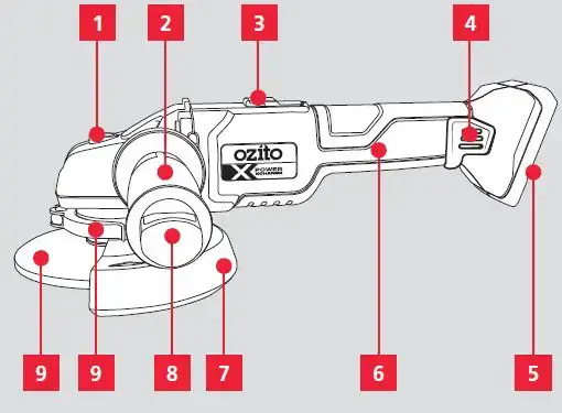
KNOW YOUR PRODUCT
BRUSHLESS 125MM ANGLE GRINDER
- Spindle Lock
- Side Handle
- Lock On Slide Switch
- Dust Guard / Ventilation Mesh
- Battery Seatin
- Sure Grip Handle
- Grinding Guard
- Pin Wrench
- Guard Locking Lever
- Grinding Disc

BATTERY & CHARGER
This tool is compatible with all batteries & chargers from the Ozito PXC range.
For optimal performance, we recommend the use of a 3.0Ah battery or higher to operate this PXC tool.
ONLINE MANUAL
Scan this QR Code with your mobile device to take you to the online manual.
ASSEMBLY
WARNING! ENSURE THE TOOL IS SWITCHED OFF AND THE BATTERY IS REMOVED BEFORE PERFORMING ANY OF THE FOLLOWING
Fitting The Side Handle
- To fit, screw the side handle clockwise into 1 of 2 handle positions.

- To remove, screw the handle anti-clockwise.
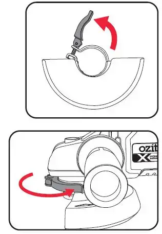
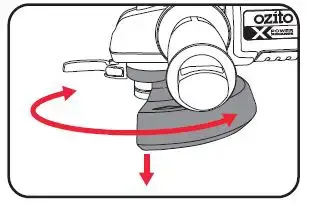
Fitting The Safety Guard
- Loosen the safety guard locking lever to allow it to spin.
- Align the notches, rotate the guard into the desired position and secure in place with the locking lever.
WARNING! DO NOT OPERATE THE ANGLE GRINDER WITHOUT THE SAFETY GUARD FITTED AS POSSIBLE INJURIES COULD OCCUR.
FITTING THE DISC
WARNING!
- ENSURE THE TOOL IS SWITCHED
OFF AND THE BATTERY IS REMOVED BEFORE PERFORMING ANY OF THE FOLLOWING TASKS. - ALWAYS WEAR GLOVES WHEN CHANGING THE DISC OR GUARD. THE DISC, GUARD AND WORKPIECE WILL BECOME HOT DURING USE.
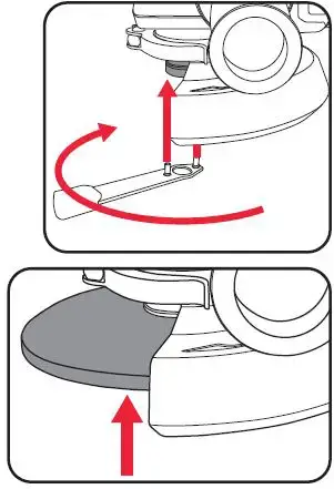
- Pull the pin wrench out from the side handle.
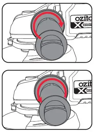
- Depress and hold the spindle lock to prevent the spindle rotating.
- Align the pins of the pin wrench to the flange holes and loosen by rotating it anti-clockwise.
- Remove the flange and replace the grinding disc on the spindle.
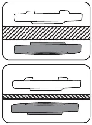
- When assembling the outer flange,ensure you select the correct orientation to suit the type of disc being fitted
Grinding disc: Place outer flange with the raised lip upwards.
Cutting disc: Place outer flange with the raised lip downwards.
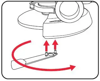
WARNING! WHEN USING THE ANGLE GRINDER WITH A CUTTING DISC, A CUTTING GUARD (NOT SUPPLIED) MUST BE FITTED PRIOR TO OPERATION. FAILURE TO DO SO MAY RESULT IN SERIOUS INJURY. - Screw the flange back onto the spindle and tighten using the pin wrench while holding the spindle lock down.
CHANGING THE GUARD
WARNING! ENSURE THE TOOL IS SWITCHED OFF AND THE BATTERY IS REMOVED BEFORE PERFORMING ANY OF THE FOLLOWING TASKS.
A safety guard should be used at all times whilst operating the angle grinder, but there are times when you should swap the guard, such as when switching from a grinding disc to a cutting disc.
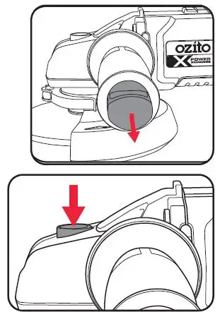
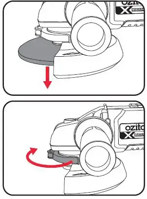
- To remove a guard, you must first remove the disc if one is installed.
- Loosen the safety guard locking lever to allow it to spin.
- Remove the guard by aligning the notches and pulling away from the tool.
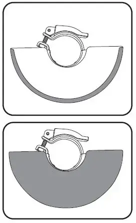
- Choose the correct guard for the job.
Semi open guards are designed for grinding whilst the fully enclosed guards are designed for cutting disks.
Use ONLY the semi-open grinding guard with a grind disc
Use ONLY the fully enclosed cutting guard with a cutting disc - Fit the correct guard to match the correct disc, rotate to the desired position and secure in place with the locking lever.
FITTING THE BATTERY
Installing The Battery Pack
- Slide the battery into the tool base until it clicks into place.
Removing The Battery Pack
- Hold down the battery release button and then slide the battery out.
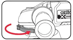
OPERATION
CONTROLS
Switching The Tool On & Off
- To turn on, hold the angle grinder firmly with both handles, press down on the back end of the switch and slide it forward.
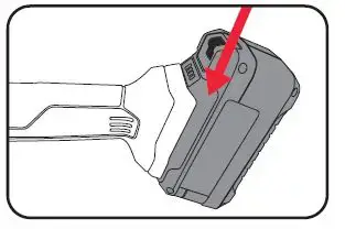
- To use the lock on function, press down on the back end of the switch, slide it fully forward and then press down on the front end of the switch to lock it in position.
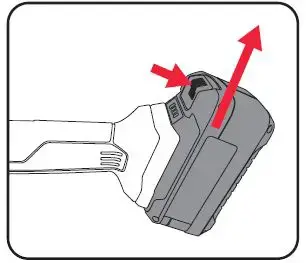
GRINDING
WARNING! ALWAYS HOLD THE SIDE HANDLE AND SURE-GRIP THE HANDLE WITH BOTH HANDS FOR ALL GRINDING AND CUTTING APPLICATIONS.
- Ensure the workpiece is securely held down.
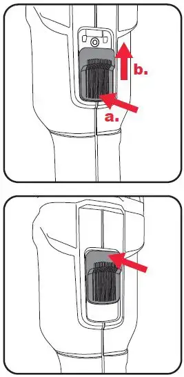
- Hold the angle grinder firmly with both handles and switch on.
- Begin grinding your workpiece. The optimum grinding angle is 10-150 to the workpiece.
Note: Do not apply excessive pressure. Allow the tool to do the work, this will prevent deep gouging.
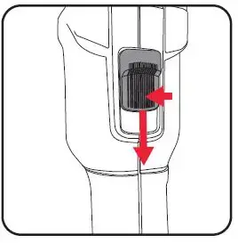
WARNING! WHEN USING THE ANGLE GRINDER WITH A CUTTING DISC, A CUTTING GUARD (NOT SUPPLIED) MUST BE FITTED PRIOR TO OPERATION. FAILURE TO DO SO MAY RESULT IN SERIOUS INJURY.
- Ensure the workpiece is securely held down.
- Hold the angle grinder firmly with both handles and switch on.
- The optimum angle is 90° to the workpiece. Do not apply excessive pressure. Allow the tool to do the work.
Note: Do not apply excessive pressure. Allow the tool to do the work
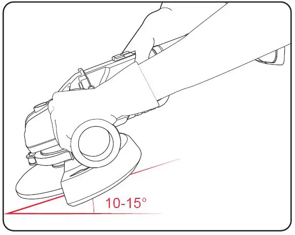
WARNING! AFTER EVERY USE, CLEAN THE VENTILATION MESH ON THE HOUSING TO PREVENT OVERHEATING THE MOTOR. THE VENTILATION MESH MUST BE USED IN ALL APPLICATIONS.
WARNING! AFTER ALL DUSTY APPLICATIONS, USE COMPRESSED AIR TO CLEAN THE SWITCH OF ANY DUST.
TROUBLESHOOTING
LED lights do not illuminate on the charger
Check the charging adaptor is securely plugged into the wall out let. Check the battery is firmly connected to the charging cradle.
Check that the charging jack is securely connected to the charging cradle.
The battery has a short run time
Ensure the battery is properly charged. It will take 4-5 charging cycles before the battery reaches optimum charge and run time. On the initial charge, the battery requires 5 hours of charging. Subsequent charging only requires 3-5 hours.
Spindle locking button will not depress
The spindle will need to be rotated until the lock can engage. Simply rotate the spindle while applying a small amount of pressure on the spindle lock.
Angle grinder does not turn on after a period of inactivity
The tool switches to ‘Standby Mode’ after 10 minutes of inactivity. To switch it back on, slide the power switch forward twice or press the battery indicator.
Standby mode protects the battery whilst not in use.
WARNING! BEFORE CLEANING OR CARRYING OUT ANY MAINTENANCE PROCEDURE, ENSURE THAT THE BATTERIES HAVE BEEN REMOVED.
Cleaning
- Keep the ventilation slots of the tool clean at all times to ensure efficient operation.
- After each use, blow air through the tool housing to ensure it is free from all dust, dirt, etc. The build-up of dust or dirt particles may cause the tool to overheat and shorten the life of the tool
- If the housing of the tool requires cleaning, do not use solvents. Use of cloth only is recommended.
- Never allow any liquid to get inside the tool, never immerse any part of the tool into a liquid.
Cleaning The Dust Guard & Ventilation Mesh
- Gently flex one side of the dust guard away from the handle.
- Unhook the dust guard from the tool.
- Use compressed air to clean the ventilation mesh on the tool and dust guard. If necessary, use a soft, dry cloth to wipe the dust guard clean.
- Press the pins on the inside of the dust guard against the tool handle and then re-attach the dust guard.
Storage
When not in use, the tool should be stored in a dry, frost-free location, keep out of children’s reach.
Note: Ozito Industries will not be responsible for any damage or injuries caused by the repair of the tool by an unauthorized person or by mishandling.
DESCRIPTION OF SYMBOLS
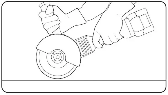
CARING FOR THE ENVIRONMENT
Power tools that are no longer usable should not be disposed of with household waste but in an environmentally friendly way. Please recycle where facilities exist. Check with your local council authority for recycling advice.
Recycling packaging reduces the need for landfills and raw materials. The reuse of recycled material decreases pollution in the environment. Please recycle packaging where facilities exist.
Check with your local council authority for recycling advice.
SPARE PARTS
Spare parts can be ordered from the Special Orders
Desk at your local Bunnings Warehouse.
For further information, or any parts not listed here,
visit www.ozito.com.au or contact Ozito Customer
Service:
Australia 1800 069 486
New Zealand 0508 069 486
E-mail: [email protected]
ELECTRICAL SAFETY
WARNING! When using mains-powered tools, basic safety precautions, including the following, should always be followed to reduce risk of fire, electric shock, personal injury and material damage. Read the whole manual carefully and make sure you know how to switch the tool off in an emergency, before operating the tool. Save these instructions and other documents supplied with this tool for future reference.
The charger has been designed for 230V and 240V only. Always check that the power supply corresponds to the voltage on the rating plate.
Note: The supply of 230V and 240V on Ozito tools are interchangeable for Australia and New Zealand.
This tools charger is double insulated; therefore no earth wire is required.
Note: Double insulation does not take the place of normal safety precautions when operating this tool. The insulation system is for added protection against injury resulting from a possible electrical insulation failure within the tool.
If the supply cord is damaged, it must be replaced by an electrician or a power tool repairer in order to avoid a hazard.
The power supply for this product’s charger should be protected by a residual current device (rated at 30mA or less). A residual current device reduces the risk of electric shock.
GENERAL POWER TOOL SAFETY WARNINGS
WARNING! Read all safety warnings and all instructions. Failure to follow the warnings and instructions may result in electric shock, fire and/or serious injury.
Save all warnings and instructions for future reference. The term “power tool” in the warnings refers to your mains-operated (corded) power tool or battery-operated (cordless) power tool.
- Work area safety
- Keep work area clean and well lit. Cluttered or dark areas invite accidents.
- Do not operate power tools in explosive atmospheres, such as in the presence of flammable liquids, gases or dust. Power tools create sparks which may ignite the dust or fumes.
- Keep children and bystanders away while operating a power tool. Distractions can cause you to lose control.
- Electrical safety
- Power tool plugs must match the outlet. Never modify the plug in any way. Do not use any adapter plugswith earthed (grounded) power tools. Unmodified plugs and matching outlets will reduce risk of electric shock.
- Avoid body contact with earthed or grounded surfaces, such as pipes, radiators, ranges and refrigerators. There is an increased risk of electric shock if your body is earthed or grounded.
- Do not expose power tools to rain or wet conditions. Water entering a power tool will increase the risk of electric shock.
- Do not abuse the cord. Never use the cord for carrying, pulling or unplugging the power tool. Keep cord away from heat, oil, sharp edges or moving parts. Damaged or entangled cords increase the risk of electric shock.
- When operating a power tool outdoors, use an extension cord suitable for outdoor use. Use of a cord suitable for outdoor use reduces the risk of electric shock.
- If operating a power tool in a damp location is unavoidable, use a residual current device (RCD) protected supply. Use of an RCD reduces the risk of electric shock.
- Personal safety
- Stay alert, watch what you are doing and use common sense when operating a power tool. Do not use a power tool while you are tired or under the influence of drugs, alcohol or medication. A moment of inattention while operating power tools may result in serious personal injury.
- Use personal protective equipment. Always wear eye protection. Protective equipment such as dust mask, non-skid safety shoes, hard hat, or hearing protection used for appropriate conditions will reduce personal injuries.
- Prevent unintentional starting. Ensure the switch is in the off-position before connecting to power source and/or battery pack, picking up or carrying the tool. Carrying power tools with your finger on the switch
or energising power tools that have the switch on invites accidents. - Remove any adjusting key or wrench before turning the power tool on. A wrench or a key left attached to a rotating part of the power tool may result in personal injury.
- Do not overreach. Keep proper footing and balance at all times. This enables better control of the power tool in unexpected situations.
- Dress properly. Do not wear loose clothing or jewellery. Keep your hair, clothing and gloves away from moving parts. Loose clothes, jewellery or long hair can be caught in moving parts.
- If devices are provided for the connection of dust extraction and collection facilities, ensure these are connected and properly used. Use of dust collection can reduce dust-related hazards.
- Do not let familiarity gained from frequent use of tools allow you to become complacent and ignore tool safety principles. A careless action can cause severe injury within a fraction of a second.
- Power tool use and care
- Do not force the power tool. Use the correct power tool for your application. The correct power tool will do the job better and safer at the rate for which it was designed.
- Do not use the power tool if the switch does not turn it on and off. Any power tool that cannot be controlled with the switch is dangerous and must be repaired.
- Disconnect the plug from the power source and/or the battery pack from the power tool before making any adjustments, changing accessories, or storing power tools. Such preventive safety measures reduce the risk of starting the power tool accidentally.
- Store idle power tools out of the reach of children and do not allow persons unfamiliar with the power tool or these instructions to operate the power tool. Power tools are dangerous in the hands of untrained users.
- Maintain power tools. Check for misalignment or binding of moving parts, breakage of parts and anyother condition that may affect the power tool’s operation. If damaged, have the power tool repaired before use. Many accidents are caused by poorly maintained power tools.
- Keep cutting tools sharp and clean. Properly maintained cutting tools with sharp cutting edges are less likely to bind and are easier to control.
- Use the power tool, accessories and tool bits etc. in accordance with these instructions, taking into account the working conditions and the work to be performed. Use of the power tool for operations different from those intended could result in a hazardous situation.
- Keep handles and grasping surfaces dry, clean and free from oil and grease. Slippery handles and grasping surfaces do not allow for safe handling and control of the tool in unexpected situations.
- Battery tool use and care
- Recharge only with the charger specified by the manufacturer. A charger that is suitable for one type of battery pack may create a risk of fire when used with another battery pack.
- Use power tools only with specifically designated battery packs. Use of any other battery packs may create a risk of injury and fire.
- When battery pack is not in use, keep it away from other metal objects, like paper clips, coins, keys, nails, screws or other small metal objects, that can make a connection from one terminal to another.
Shorting the battery terminals together may cause burns or a fire. - Under abusive conditions, liquid may be ejected from the battery; avoid contact. If contact accidentally occurs, flush with water. If liquid contacts eyes, additionally seek medical help. Liquid ejected from the battery may cause irritation or burns.
- Do not use a battery pack or tool that is damaged or modified. Damaged or modified batteries may exhibit unpredictable behaviour resulting in fire, explosion or risk of injury.
- Do not expose a battery pack or tool to fire or excessive temperature. Exposure to fire or temperature above 130°C may cause explosion.
- Follow all charging instructions and do not charge the battery pack or tool outside the temperature range specified in the instructions. Charging improperly or at temperatures outside the specified range may damage the battery and increase the risk of fire.
- Service
- Have your power tool serviced by a qualified repair person using only identical replacement parts. This will ensure that the safety of the power tool is maintained.
- Never service damaged battery packs. Service of battery packs should only be performed by the manufacturer or authorized service provider.
ANGLE GRINDER SAFETY WARNINGS
WARNING! This appliance is not intended for use by persons (including children) with reduced physical, sensory or mental capabilities, or lack of experience and knowledge, unless they have been given supervision or instruction concerning use of the appliance by a person responsible for their safety.
- This power tool is intended to function as a grinder, sanding or cut-off tool. Read all safety warnings, instructions, illustrations and specifications provided with this power tool. Failure to follow all instructions listed below may result in electric shock, for and/or serious injury.
- Operations such as wire brushing, or polishing are not recommended to be performed with this power tool.
- Operations for which the power tool was not designed may create a hazard and cause personal injury.
- Do not use accessories which are not specifically designed and recommended by the tool manufacturer. Just because the accessory can be attached to your power tool, it does not assure safe operation.
- The rated speed of the accessory must be at least equal to the maximum speed marked on the power tool.Accessories running faster than their rated speed can break and fly apar
- The outside diameter and the thickness of your accessory must be within the capacity rating of your power tool. Incorrectly sized accessories cannot be adequately guarded or controlled
- The arbour size of wheels, flanges, backing pads or any other accessory must properly fit the spindle of the power tool. Accessories with arbour holes that do not match the mounting hardware of the power tool will run out of balance, vibrate excessively and may cause loss of control
- Do not use a damaged accessory. Before each use inspect the accessory such as abrasive wheels for chips and cracks, backing pad for cracks, tear or excess wear, wire brush for loose or cracked wires. If power tool or accessory is dropped, inspect for damage or install an undamaged accessory. After inspecting and installing an accessory, position yourself and bystanders away from the plane of the rotating accessory and run the power tool at maximum no-load speed for one minute. Damaged accessories will normally break apart during this test time
- Wear personal protective equipment. Depending on application, use face shield, safety goggles or safety glasses. As appropriate, wear dust mask, hearing protectors, gloves and workshop apron capable of stopping small abrasive or work piece fragments. The eye protection must be capable of stopping flying debris generated by various operations . The dust mask or respirator must be capable of filtrating particles generated by your operation. Prolonged exposure to high intensity noise may cause hearing loss
- Keep bystanders a safe distance away from work area. Anyone entering the work area must wear personal protective equipment. Fragments away and cause injury beyond immediate area of operation
- Hold power tool by insulated gripping surfaces only, when performing an operation where the cutting accessory may contact hidden wiring or its own cord. Cutting accessory contacting a “live” wire may make exposed metal parts of the power tool “live” and shock the operator
- Never lay the power tool down until the accessory has come to a complete stop. The spinning accessory may grab the surface and pull the power tool out of your control
- Do not run the power tool while carrying it at your side. Accidental contact with the spinning accessory could snag your clothing, pulling the accessory into your body.
- Regularly clean the power tool’s air vents. The motor’s fan will draw the dust inside the housing and excessive accumulation of powdered metal may cause electrical hazards.
- Do not operate the power tool near flammable materials. Sparks could ignite these materials
- Do not use accessories that require liquid coolants. Using water or other liquid coolants may result in electrocution or shock.
- Kickback is a sudden reaction to a pinched or snagged rotating wheel, backing pad, brush or any other accessory.
Pinching or snagging causes rapid stalling of the rotating accessory which in turn causes the uncontrolled power tool to be forced in the direction opposite of the accessory’s rotation at the point of the binding. For example, if an abrasive wheel is snagged or pinched by the work piece, the edge of the wheel that is entering into the pinch point can dig into the surface of the material causing the wheel to climb out or kick out. The wheel may either jump toward or away from the operator, depending on direction of the wheel’s movement at the point of pinching. Abrasive wheels may also break under these conditions. Kickback is the result of power tool misuse and/or incorrect operating procedures or conditions and can be avoided by taking proper precautions as given below. - Maintain a firm grip on the power tool and position your body and arm to allow you to resist kickback forces.
Always use auxiliary handle, if provided, for maximum control over kickback or torque reaction during start-up.
The operator can control torque reactions or kickback forces, if proper precautions are taken. - Never place your hand near the rotating accessory. Accessory may kickback over your hand.
- Do not position your body in the area where power tool will move if kickback occurs. Kickback will propel the tool in direction opposite to the wheel’s movement at the point of snagging.
- Use special care when working corners, sharp edges etc. Avoid bouncing and snagging the accessory. Corners, sharp edges or bouncing have a tendency to snag the rotating accessory and cause loss of control or kickback.
- Do not attach a saw chain woodcarving blade or toothed saw blade. Such blades create frequent kickback and loss of control.
- Use only wheel types that are recommended for your power tool and the specific guard designed for the selected wheel. Wheels for which the power tool was not designed cannot be adequately guarded and are unsafe.
- The guard must be securely attached to the power tool and positioned for maximum safety, so the least amount of wheel is exposed towards the operator. The guard helps to protect operator from broken wheel fragments and accidental contact with wheel.
- Wheels must be used only for recommended applications. For example: do not grind with the side of cut-off wheel. Abrasive cut-off wheels are intended for peripheral grinding, side forces applied to these wheels may cause them to shatter.
- Always use undamaged wheel flanges that are of correct size and shape for your selected wheel. Proper wheel flanges support the wheel thus reducing the possibility of wheel breakage. Flanges for cut-off wheels may be different from grinding wheel flanges.
- Do not use worn down wheels from larger power tools. Wheel intended for larger power tool is not suitable for the higher speed of a smaller tool and may burst.
- Additional safety instructions for abrasive cutting-off operations:
- Do not “jam” the cut-off wheel or apply excessive pressure. Do not attempt to make an excessive depth of cut.
Overstressing the wheel increases the loading and susceptibility to twisting or binding of the wheel in the cut and the possibility of kickback or wheel breakage. - Do not position your body in line with and behind the rotating wheel. When the wheel, at the point of operation, is moving away from your body, the possible kickback may propel the spinning wheel and the power tool directly at you.
- When wheel is binding or when interrupting a cut for any reason, switch off the power tool and hold the power tool motionless until the wheel comes to a complete stop. Never attempt to remove the cut-off wheel from the cut while the wheel is in motion otherwise kickback may occur. Investigate and take corrective action to eliminate the cause of wheel binding.
- Do not restart the cutting operation in the work piece. Let the wheel reach full speed and carefully reenter the cut. The wheel may bind, walk up or kickback if the power tool is restarted in the workpiece.
- Support panels or any oversized work piece to minimize the risk of wheel pinching and kickback. Large workpieces tend to sag under their own weight. Supports must be placed under the workpiece near the line of cut and near the edge of the work piece on both sides of the wheel.
- Use extra caution when making a “pocket cut” into existing walls or other blind areas. The protruding wheel may cut gas or water pipes,electrical wiring or objects that can cause kickback.
- Do not use excessively oversized sanding disc paper. Follow manufacturers recommendations, when selecting sanding paper. Larger sanding paper extending beyond the sanding pad presents a laceration hazard and may cause snagging, tearing of the disc or kickback.
- When using abrasive cutting wheels, a cutting guard MUST be fitted to your angle grinder. These cutting guards are available as a spare part and can be ordered through the special orders desk.