![]() 10A PWM
10A PWM
Solar Charge Controller
Version 1.0
![]()
![]() Important Safety Instructions
Important Safety Instructions![]()
Please save these instructions.
This manual contains important safety, installation, and operating instructions for the charge controller. The following symbols are used throughout the manual:
![]() Indicates a potentially dangerous condition. Use extreme caution when performing this task.
Indicates a potentially dangerous condition. Use extreme caution when performing this task.
![]() Indicates a critical procedure for safe and proper operation of the controller
Indicates a critical procedure for safe and proper operation of the controller
![]() Indicates a procedure or function that is important to the safe and proper operation of the controller.
Indicates a procedure or function that is important to the safe and proper operation of the controller.
General Safety Information
- Read all of the instructions and cautions in the manual before beginning the installation.
- There are no serviceable parts for this controller. Do NOT disassemble or attempt to repair the controller.
- Make sure all connections going into and from the controller are tight. There may be sparks when making connections, therefore, make sure there are no flammable materials or gases near the installation.
Charge Controller Safety
- NEVER connect the solar panel array to the controller without a battery. The battery must be connected first. This may cause a dangerous occurrence where the controller would experience a high open-circuit voltage at the terminals.
- Ensure input voltage does not exceed 50 VDC to prevent permanent damage. Use the Open Circuit (Voc) to make sure the voltage does not exceed this value when connecting panels together in series.
- The charge controller should be installed indoors in a well-ventilated, cool, and dry environment.
- Do NOT allow water to enter the controller.
Battery Safety
- Do NOT let the positive (+) and negative (-) terminals of the battery touch each other.
- Use only sealed lead-acid, flooded, gel or lithium batteries which must be deep cycle.
- Explosive battery gases may be present while charging. Be certain there is enough ventilation to release the gases.
- Be careful when working with large lead-acid batteries. Wear eye protection and have fresh water available in case there is contact with the battery acid.
- Over-charging and excessive gas precipitation may damage the battery plates and activate material shedding on them. Too high of an equalizing charge or too long of one may cause damage. Please carefully review the specific requirements of the battery used in the system.
- Equalization is carried out only for non-sealed / vented / flooded/ wet cell lead-acid batteries.
- Do NOT equalize VRLA type AGM / GEL / LITHIUM batteries UNLESS permitted by battery manufacturer.
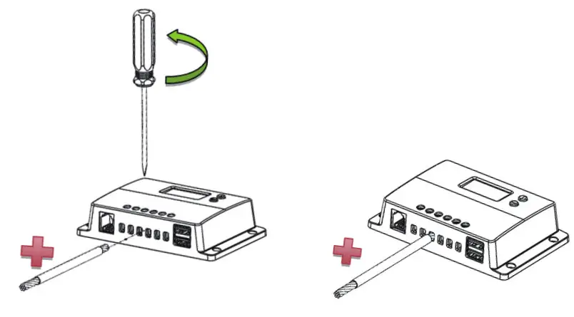
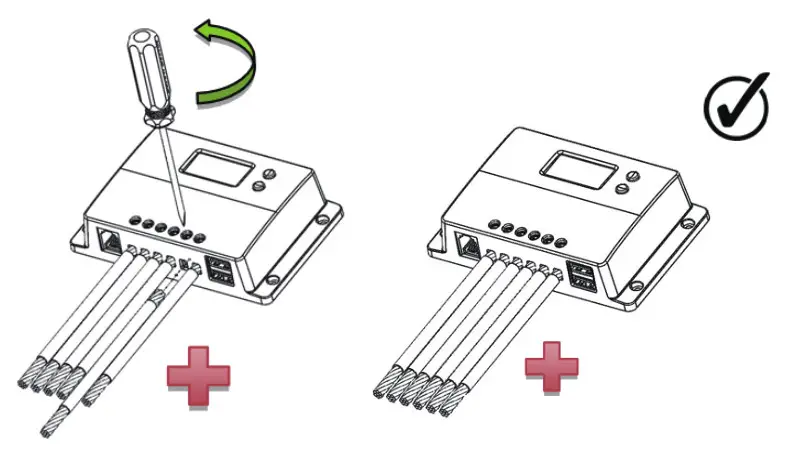
![]() Connect battery terminals to the charge controller BEFORE connecting the solar panel (s) to the charge controller. NEVER connect
Connect battery terminals to the charge controller BEFORE connecting the solar panel (s) to the charge controller. NEVER connect
solar panels to the charge controller until the battery is connected.
General Information
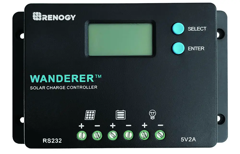
The Wanderer is an advanced charge controller for off-grid solar applications. Integrating highly efficient PWM charging, this controller increases battery life and improves system performance. It can be used for 12V/24V battery banks. The controller is embedded with self-diagnostics and electronic protection functions that prevent damages from installation mistakes or system faults.
Key Features
- Automatically detects 12V or 24V DC system voltages, 10A Charging Capacity
- Deep Cycle Sealed, Gel and Flooded battery options
- 4 Stage PWM charging: Bulk, Boost. Float, and Equalization
- Temperature compensation and correcting the charging and discharging parameters automatically, improving battery lifetime
- Protection against: overcharging, over current, short-circuit,reverse current and reverse polarity
- Backlit LCD screen for displaying system operation, diverse load control and error codes
- Integrated 5V 2A USB ports for extra charging
- Integrated communication port for remote monitoring
- Charges over-discharged lithium-ion batteries
- Negative ground charge controller
PWM Technology
The Wanderer utilizes Pulse Width Modulation (PWM) technology for battery charging. Battery charging is a current-based process so controlling the current will control the battery voltage. For the most accurate retum of capacity, and for the prevention of excessive gassing pressure, the battery is
required to be controlled by specified voltage regulation set points for Absorption, Float, and Equalization charging stages. The charge controller uses automatic duty cycle conversion, creating pulses of current to charge the battery.
The duty cycle is proportional to the difference between the sensed battery voltage and the specified voltage regulation set point. Once the battery reached the specified voltage range, pulse currant charging mode allows the battery to react and allows for an acceptable rate of charge for the battery level.
Four Charging Stages
The Wanderer has a 4-stage battery charging algorithm for rapid, efficient, and safe battery charging. They include Bulk Charge, Boost Charge, Float Charge, and Equalization.
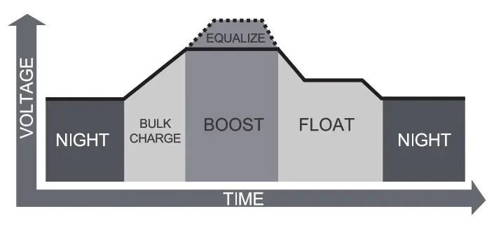 Bulk Charge: This algorithm is used for day-to-day charging. It uses 100% of available solar power to recharge the battery and is equivalent to constant current.
Boost Charge: When the battery has charged to the Boost voltage set-point, it undergoes an absorption stage which is equivalent to constant voltage regulation to prevent heating and excessive gassing in the battery. The Boost time is 120 minutes.
Float Charge: After Boost Charge, the controller will reduce the battery voltage to a float voltage set point. Once the battery is fully charged, there will be no more chemical reactions and all the charge current would turn into heat or gas.Because of this, the charge controller will reduce the voltage charge to smaller quantity, while lightly charging the battery. The purpose for this is to offset the power consumption while maintaining a full battery storage capacity.
In the event that a load drawn from the battery exceeds the charge current, the controller will no longer be able to maintain the battery to a Float set point and the controller will end the float charge stage and refer back to bulk charging.
Equalization: Is carried out every 28 days of the month. It is intentional overcharging of the battery for a controlled period. Certain types of batteries benefit from periodic equalizing charge, which can stir the electrolyte, balance battery voltage and complete chemical reactions. Equalizing charge increases the battery voltage, higher than the standard complement voltage, which gasifies the battery electrolyte.
![]()
Once equalization is active in the battery charging, it will not exit this stage unless there is adequate charging current from the solar panel. There should be NO load on the batteries when in the equalization charging stage.
Over-charging and excessive gas precipitation may damage the battery plates and activate material shedding on them. Too high of equalizing charge or for too long may cause damage. Please carefully review the specific requirements of the battery used in the system.
Lithium Battery Activation
The Wanderer PWM charge controller has a reactivation feature to awaken a sleeping lithium battery. The protection circuit of Li-ion battery will typically tum the battery off and make it unusable if over-discharged. This can happen when storing a Li-ion pack in a discharged state for any length of time as self-discharge would gradually deplete the remaining charge. Without the wake-up feature to activate and charge batteries, these batteries would become unserviceable and the packs would be discarded. The Wanderer will apply a small
Identification of Parts
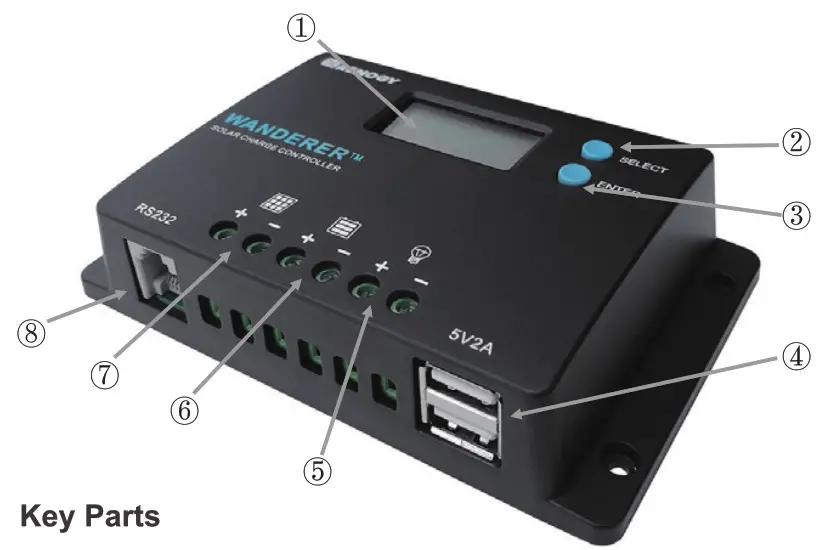
Key Parts
- LCD Screen
- Select Button
- Enter Button
- USB Ports
- Load Terminals
- Battery Teminals
- PV Terminals
- RS232 Communication port
Installation
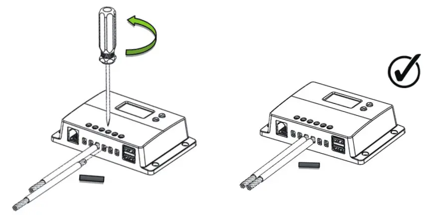
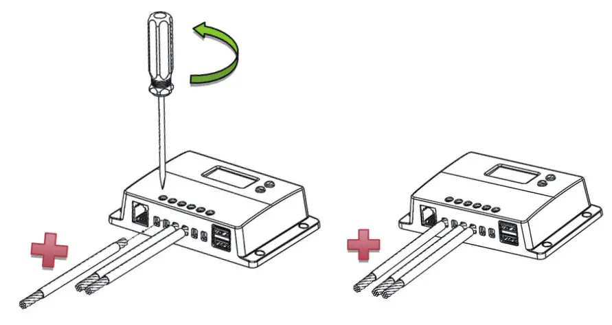
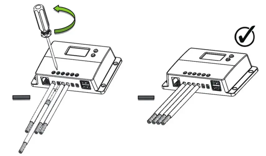
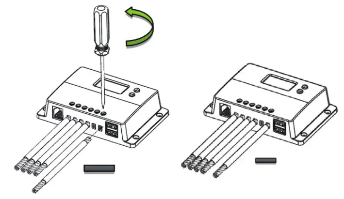
![]()
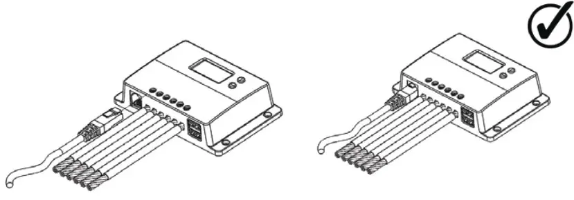
Connect battery terminal wires to the charge controller FIRST, then connect the solar panel(s) to the change controller. NEVER connect solar panel to charge controller before the battery.
![]()
Do not over-torque or over-tighten the screw terminals. This could potentially break the piece that holds the wire to the charge controller.
Refer to the technical specifications for max wire sizes on the controller and for the maximum amperage going through wires.
Wiring
Battery
 Solar Panel
 Load
Load
 Bluetooth Module Communication (optional)
Mounting Recommendations
![]()
Never install the controller in a sealed enclosure with flooded batteries. Gas can accumulate and there is a risk of explosion.
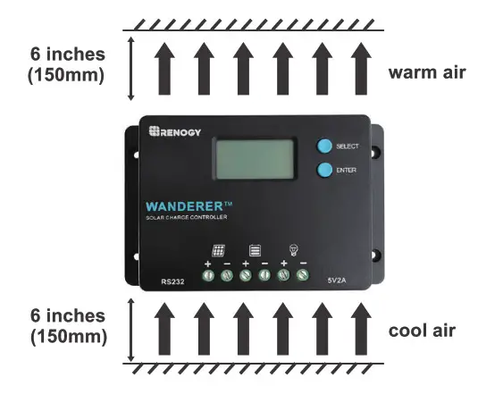
- Choose Mounting Location—place the controller on a vertical surface protected from direct sunlight, high temperatures, and water. Make sure there is good ventilation.
- Check for Clearance—verify that there is sufficient room to fun wires, as well as clearance above and below the controller for ventilation. The clearance should be at least 6 inches (150mm).
- Mark Holes
- Drill Holes
- Secure the charge controller.
Operation
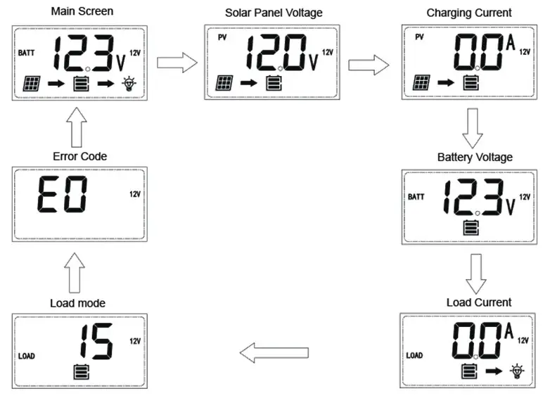
After connecting the battery to the charge controller, the controller will turn on automatically. Assuming normal operation, the charge controller will cycle through different displays. The user can adjust some parameters based on the display screen. The user can manually cycle through the display screens by using the “SELECT” and “ENTER” buttons.
- SELECT Cycles forwards through the different display screens.
- ENTER Cycles backward through the different select screens &Tum the load ON/OFF in the Manual Mode
Main Display
 LCD Indicators
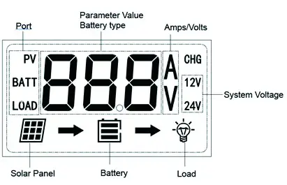
| Icon or Value | State | Description |
| Steady on | Solar Panels Charging Battery | |
| 3 Bars Flashing | Battery Voltage (16.1V+) | |
| 3 Bars | Battery Voltage (12.9V- 16.0V) | |
| 2 Bars | Battery Voltage (12.5-12.8V) | |
| 1 Bar | Battery Voltage (11.6-12.4V) | |
| No Bars | Battery Voltage (11.5V and below) | |
| No Bars Flashing | Battery Voltage (10.9V and below) | |
| Steady on | Load is On |
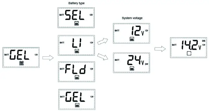
Programming Battery Type
To enter the bettery programming settings hover over the Battery Voltage screen and press down the Enter button. When the bettery type starts to flash press the Select button to cycle through the battery types and press Enter Finalize selection. When selecting the Lithium setting the user can charge battery voltage from 12V to 24V and select the charging voltage.
 Programming Load Terminal
To enter the load programming settings hover over the load Mode screen and hold the Enter button to cycle through the load types and press Enter to finalize sececiton.
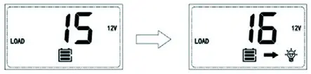
| Setting | Mode | Descroption |
| 0 | Automatic (On/Off) | The load will turn on at night when the solar panel is no longer producing any power after a short time delay. The load will turn off when the panel starts producing power. |
| 1-14 | Time control | When the panel is no longer producing power, the load will be ON for 1-14 hours or until the panel starts producing power. |
| 15 | Manual | In this mode, the user can turn the Load On/Off by pressing the Enter button at any time. |
| 16 | Test | Used to troubleshoot load teminal (No Time Delay). When voltage is detected load will be off and when no voltage is detected load will be on |
| 17 | 24 Hr | The load will be on for 24 hours a day. |
Wanderer Protections
| Protection | Behavior |
| PV Array Short Circuit | When PV short circuit occurs, the controller will stop charging. Clear it to resume normal operation |
| PV Overcurrent | The controller will limit the battery charging current to the maximum battery current rating. Therefore, an oversized solar array will not operate at peak power. |
| Load Overload | If the current exceeds the maximum load current rating 1.05 times, the controller will disconnect the load. Overloading must be cleared up by reducing the load and restarting the controller. |
| Load short circuit | Fully protected against the load wiring short-circuit. Onece the load short (more than quadruple rate current), the load short protection will start automatically. After 5 automatic load reconnect attempts, the faults must be ceared by restarting the controller. |
| PV Reverse Polarity | The controller will not operate if the PV wires are switched. Wire them correctly to resume normal controller operation. |
| Battery Reverse Polarity | The controller will not operate if the batery wires are switched. Wire them correctly to resume normal controller operation. |
Error Codes
| Error Number | Description |
| E0 | No error detected |
| E01 | Battery over-discharged |
| E02 | Battery over-voltage |
| E04 | Load short circuit |
| E05 | Load overloaded |
| E06 | Controller over-temperature |
| E08 | PV input over-current |
| E10 | PV over-voltage |
| E13 | PV reverse polarity |
| E14 | Battery reverse polarity |
Maintenance
Risk of Electric Shock! Make sure that all power is turned off before touching the terminals on the charge controller.
For best controller performance, it is recommended that these tasks be performed from time to time.
- Check that controller is mounted in a clean, dry, and ventilated area.
- Check wiring going into the charge controller and make sure there is no wire damage or wear.
- Tighten all terminals and inspect any loose, broken, or bumt up connections.
- Check to make sure none of the terminals have any corrosion, insulation damage, high temperature, or any burmt/discoloration marks.
Fusing
Fusing is a recommendation in PV systems to provide a safety measure for connections going from panel to controller and controller to battery. Remember to always use the recommended wire gauge size based on the PV system and the controller.
| NEC Maximum Current for different Copper Wire Sizes | |||||||||
| AWG | 16 | 14 | 12 | 10 | 8 | 6 | 4 | 2 | 0 |
| Max. Current | 10A | 15A | 20A | 30A | 55A | 75A | 95A | 130A | 170A |
Fuse from Controller to Battery
Controller to Battery Fuse = Current Rating of Charge Controller Ex. Wanderer 10 = 10A fuse from Controller to Battery
Fuse from Solar Panel(s) to Controller
Ex. 200W; 2 X 100 W panels
Parallel
Total Amperage = Isc1 + Isc2 = (5.75A + 5.75A) * 1.56
Fuse = minimum of 11.5 * 1.56 = 17.94= 18A fuse
Technical Specifications
| Description | Parameter |
| Nominal Voltage | 12V/24V Auto Recognition |
| Rated Charge Current | 10A |
| Max. PV Input Voltage | 50 VDC |
| USB Output | 5V, 2A max |
| Self-consumption | ≤10mA |
| Temperature Compensation Coefficient | -3m V/C/2V |
| Operating Temperature | -25 ºC to +45 ºC Ι -31 ºF to 113 ºF |
| Storage Temperature | -35 ºC to +80 ºC I -31 ºF to 176 ºF |
| Enclosure | IP20 |
| Terminals | Up to #12 AWG |
| Weight | 0.27 lbs. |
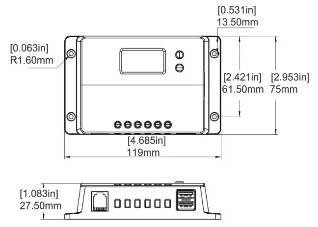
| Dimensions | 4.68 x 2.95 x 1.08 inches |
| Communication | RS232 |
| Battery Type | Sealed (AGM), Gel, Flooded and Lithium |
Battery Charging Parameters
All the coefficient is referred to 25 °C
| Battery | GEL | SEALED | FLOODED | LI(LFP) |
| High Voltage Disconnect | 16V | 16V | 16V | 16V |
| Over Voltage Reconnect | 15.0 V | 15.0 V | 15.0 V | 15.0 V |
| Equalization Voltage | —– | 14.6 | 14.6 | —– |
| Boost Voltage | 14.2 V | 14.2 V | 14.2 V | 14.2 V (User: 12.6-16V) |
| Float Voltage | 13.8 V | 13.8 V | 13.8 V | —- |
| Boost Return Voltage | 13.2 V | 13.2 V | 13.2 V | 13.2 V |
| Low Voltage Reconnect | 12.6 V | 12.6 V | 12.6 V | 12.6 V |
| Discharging Limit Voltage | 10.8 V | 10.8 V | 10.8 V | 10.8 V |
| Equalization Duration | —– | 2 hours | 2 hours | —– |
| Boost Duration | 2 hours | 2 hours | 2 hours | —– |
Dimensions
![]()
2775 E. Philadelphia St., Ontario, CA 91761
1-800-330-8678
Renogy reserves the right to change the
contents of this manual without notice.
RENOGY Monocrystalline Solar Panel

Key Features
With a sleek design and a durable frame, the Renogy 100 Watt 12 Volt Monocrystalline Panel provides you with the highest efficiency per area and is the perfect item for off-grid applications.
- High module conversion efficiency
- Top-ranked PTC rating
- Quick and inexpensive mounting
- 100% EL testing on all Renogy modules
- No hot spots guaranteed
The Renogy 100 Watt Monocrystalline Panel can be used in various off-grid applications that include 12 and 24 volts arrays, water pumping systems, signaling systems, and other off-grid applications.

25 Years Power Output Warranty
5 Years Material and Workmanship Warranty
Maximum Power at STC* – 100 W
Optimum Operating Voltage (Vmp) – 18.9 V
Optimum Operating Current (Imp) – 5.29 A
Open Circuit Voltage (Voc) – 22.5 V
Short Circuit Voltage (Isc) – 5.75 A
Module Efficiency – 15.47%
Maximum System Voltage – 600 VDC UL
Maximum Series Fuse Rating – 15 A
Solar Cell Type – Monocrystalline (4.92 x 4.92 in)
Number of Cells – 36 (4 x 9)
Dimensions – 47.0 x 21.3 x 1.4in (1195 x 541 x 35mm)
Weight – 16.5 lbs (7.5 kg)
Front Glass – Tempered Glass 0.13 in (3.2 mm)
Frame – Anodized Aluminium Alloy
Connectors – MC4 Connectors
Fire Rating – Class C
Operating Module Temperature -40°F to 176°F
Nominal Operating Cell Temperature (NOCT) – 47±2ºC
Temperature Coefficient of Pmax -0.44%/ºC
Temperature Coefficient of Voc -0.30%/ºC
Temperature Coefficient of Isc -0.04%/ºC
Rated Current – 30A
Maximum Voltage – 1000VDC
Maximum AWG Size Range – 10 AWG
Temperature Range – -40ºF to 194ºF
IP Rating – IP 67
IP Rating – IP 65
Diode Type – HY 10SQ050
Number of Diodes – 2 Diode(s)
Output Cables – 14 AWG (2.10 ft long)
![]()
*All specifications and data described in this data sheet are tested under Standard Test Conditions (STC – Irradiance: 1000W/m2, Temperature: 25 ºC, Air Mass: 1.5) and may deviate marginally from actual values. Renogy and any of its affiliates have reserved the right to make any modifications to the information on this data sheet without notice. It is our goal to supply our customers with the most recent information regarding our products. These data sheets can be found in the downloads section of our website, www.renogy.com
Renogy | www.renogy.com | [email protected] | T: 800-330-8678 2775 E. Philadelphia St., Ontario, CA 91761
]]>
General Information
The Renogy BT-1 is a great addition to any compatible Renogy solar charge controllers. Powered by its RJ12 communication port, the BT-1 provides wireless monitoring of system data and allows users to change parameters through the Renogy BT/Renogy DCHome smart phone App.
Key Features
- Wirelessly monitor and control compatible solar charge controllers via Bluetooth
- Connects to our user-friendly smart phone App, Renogy BT/Renogy DCHome, to keep track of your system
- Embedded exclusive Bluetooth chip with high efficiency and low energy consumption
- Bluetooth 4.2 and BLE technology provides fast and uninterrupted communication
- Powered directly through RJ12 communication port
- Signal range up to 82ft
- Two LED lights indicate the power and Bluetooth connection condition
Identification of Parts

Operation
* Connection
Connect the BT-1 Bluetooth module to any Renogy solar charge controller with an RJ12 port and RS232 communication protocol.
* Communication status indicator
Green Power Indictor:
Status: Note
Solid (Green): Power On
Off Power: Off
Blue Communication Indicator:
Status: Note
Flashing (Blue): Communicating
Off: Stand by
* Compatible Models
Compatible Models : All Renogy Controllers with RJ12 port
Communication Protocol : RS232
Port Type : RJ12
Technical Specifications
Description: Parameter
Model: BT-1
Input Voltage: 12V
Standby Power Consumption: 0.04W
Operating Power Consumption: 0.05W
Communication Range: ≤82ft
Serial Baud Rate: Fixed Baud Rate 9600bps
Communication Protocol: RS232
Port Type: RJ12
Cable Length: 5.00m (16.4ft)
Dimensions: 67.3 X 35 X 14mm / 2.65 X 1.38 X 0.55in
Installation Dimensions: 67.3 φ3.5mm(2.66 φ 0.14in)
Operation Temperature: -20℃~85℃(-4°F to 185°F)
Protection Grade: IP54
Weight: 130g(4.58oz)
To Download App
- The Android version of the Renogy BT APP is available to download on Renogy.com and the Google Play Store. In the Google Play Store, simply search “Renogy BT”or “Renogy DCHome” in App store to download.
To Download App - For IOS version, simply search “Renogy BT” or “Renogy DCHome”in App store to download.
- How to Connect via Bluetooth Please ensure your device’s Bluetooth setting is turned on.
Select:
Configuration > Search Devices > Device
* The admin password in App is 135790123
The green indicator on the BT-1 will turn on once it has successfully connected to the power.
The blue indicator on the BT-1 will blink once it has successfully connected and during communication.
Warning
Please read this guide carefully to avoid incorrect connections that can cause the battery monitor to malfunction and/or create a fire hazard. Disconnect the negative pole of the battery before installation.
- The Renogy Battery Monitor can’t be exposed in the sun for a long time or in the environment with large amounts of ultraviolet radiation when using or storing, in winter (< -10℃) and summer (>60℃) otherwise the life span of the LCD will be shortened.
Battery Safety
- Do NOT let the positive (+) and negative (-) terminals of the battery touch each other.
- Explosive battery gases may be present while charging. Be certain there is enough ventilation to release the gases.
- Be careful when working with large lead acid batteries. Wear eye protection and have fresh water available in case there is contact with the battery acid.
- It is the user’s responsibility to operate the equipment in a safe manner. Do not charge batteries in an enclosed environment unless allowed by the manufacturer of the battery.
- Never connect a load to a battery without using fuses or circuit breakers.
- Please follow the battery manufacturer’s safety instructions.
General Information
The Renogy Battery Monitor is a high precision device (also known as coulometer), which can test the voltage, current, and capacity of a battery to help users know the state of charge at any time. The Renogy Battery Monitor has a memory function which allows users to set a low voltage capacity alarm. It is suitable for mobile and portable equipment, e-bike, motorcycles, electric wheelchairs, and so on.
- The Renogy Battery Monitor is suitable for lithium batteries, lead acid batteries and nickel-metal hydride batteries that have voltage from 10V to 120V.
Identification of Parts
- LCD Interface

- Shunt/Sampler Holder

- 500A Shunt/Sampler
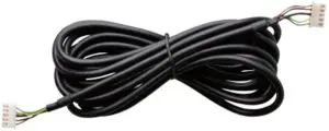
- 20ft (6m) Shielded Wire
- 3ft (1m) 20 AWG B+ Wire

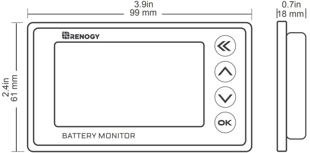
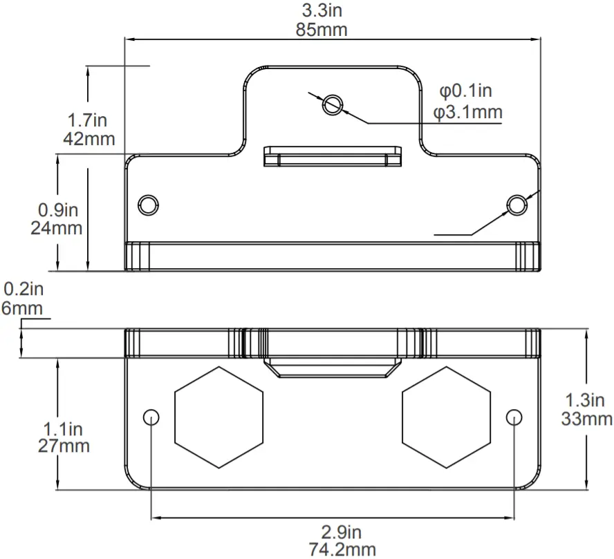
Dimension
Installation
Connection/Setup
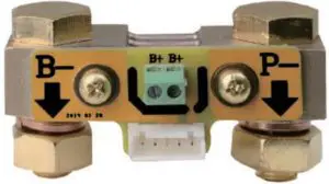
First, connect the Shunt in series to the negative circuit of your battery. B- of shunt connects to B- of the battery. P- of shunt connects to P- of output and C- of charge.
Then take a wire of 0.3-0.75 mm². One end of the wire connects to positive of battery, another end connects to B+ of Shunt (either one is ok).
Finally connect the Shunt to the Renogy Battery Monitor by the shielded wire and the screen of the Renogy Battery Monitor display should turn on.
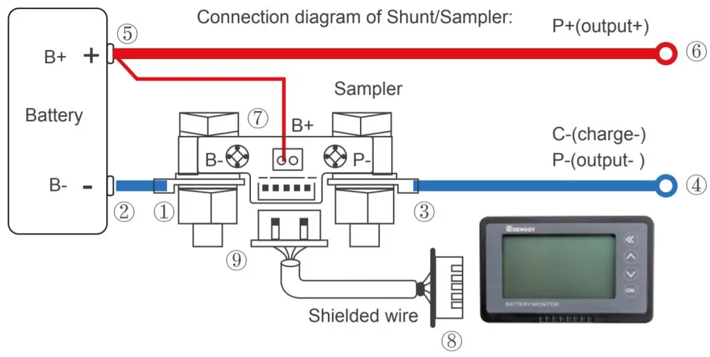
Attention: Please connect as shown. The shunt must be series connected to the negative circuit, DO NOT connect to the positive circuit.
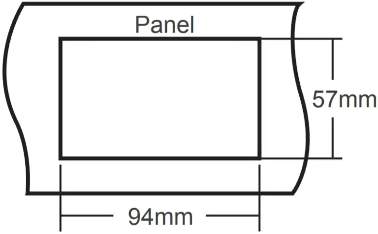
Mounting
The Renogy Battery Monitor is fixed by tabs, so it is easy to install. First, open a rectangular orifice on your equipment panel according to the size. Then put The Renogy Battery Monitor into the rectangular orifice, and make sure the tabs are locked.
Operation
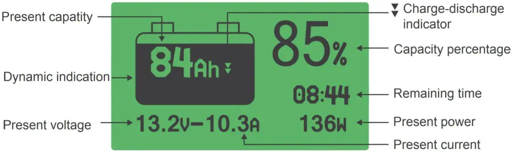
Interface description
Use steps
- Connect and check the current: Power on after completing the connection as shown, the screen should display capacity percentage. If the screen has no response, please check the connection. Then charge or discharge the battery and check whether the display current is equal to the actual current. If the deviation is large, please check the connection.
- Capacity calibration: On first use, the percentage and capacity are not the actual value, you need to calibrate the capacity to either 100% or 0%.
First set the usable AH capacity of the battery as the preset AH capacity.
For Lithium and Sealed Lead Acid batteries to calibrate to 100% charge the battery fully and hold the “up” key for 3s to set the capacity to 100%
For Lithium batteries to calibrate to 0% discharge the battery completely and hold the “down” button key for 3s to set the capacity to zero.
This will only have to be done on initial installation of the Renogy Battery Monitor or if the Battery Bank is replaced. - Check and reset the actual capacity: If you find the displayed capacity doesn’t match the actual capacity during use, please check and reset the actual capacity.
For Lithium batteries discharge the battery to 0% and hold the “down” key for 3s to set the capacity to 0, then set the preset capacity as large as possible.
Now charge the battery fully and the displayed AH capacity should be the actual usable capacity. Then set the displayed AH capacity as the preset AH capacity.
For Sealed Lead Acid batteries it is recommended to set the AH lower than the usable rating after conducting a capacity test or consulting the battery manufacturer.
User settings
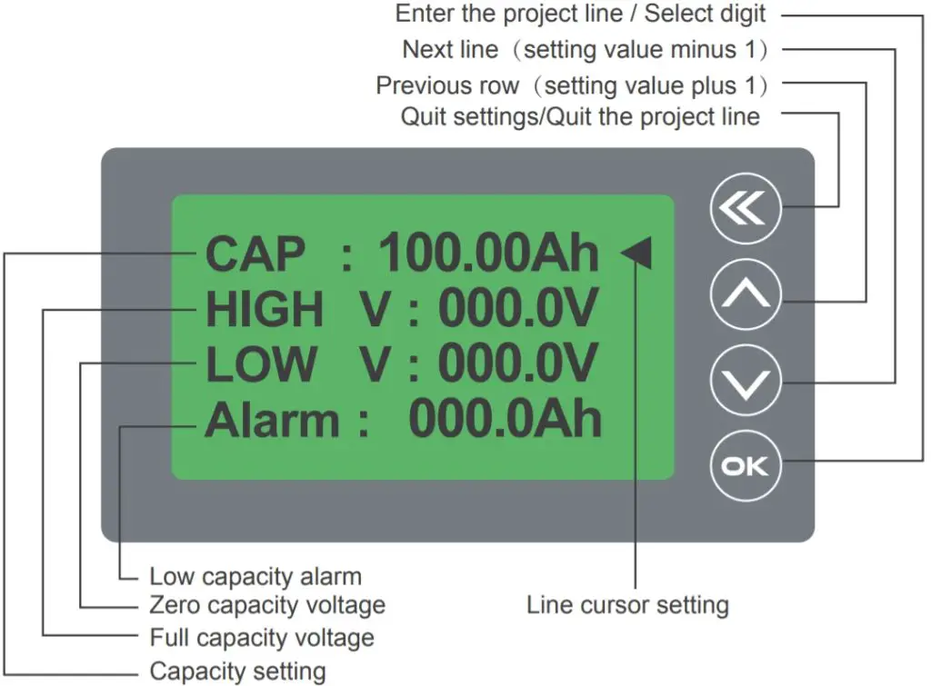
Preset capacity and voltage setting:
- Press the
 key for 3s to enter setting menu;
 - Click
 or
or  key to select the setting items:
- CAP—Preset capacity: An initial capacity has been set at the factory, please set it according to the real capacity of your battery.
- HIGH V-Full capacity voltage: When the voltage is higher than the set value, the capacity will be automatically set to 100%.
- LOW V-Zero capacity voltage: When the voltage is lower than the set value, the capacity will be automatically set to 0%. If the discharge continues, the voltage value will flash, and the alarm will beep once every 10s.
- ALARM-Alarm setting: When the battery capacity is below the set capacity, the percentage and battery symbol will flash and the alarm will beep once every 10s.
- Attention: If you need to set the HIGH V and LOW V values, please confirm the full charge voltage and all discharge voltage specifications of your battery.
- Select CAP and click the key to enter the preset capacity setting; The set value will flicker, click the key can select other values, click the or key to select the correct values after this click the
 key to quit preset capacity setting.
 - We can set other items with the same method as preset capacity. When all the items are set and all the values are correct, click the key to save the set and quit the setting menu.
Set capacity to zero or full:
On first use or change of the battery bank, the memory capacity should be set zero or full: In the main interface, hold the key for 3s to set the capacity zero, the percentage will be 0%; hold the key for 3s to set the capacity full, the percentage will be 100%.
Sleep mode wake up operation
- When the battery current is low, the Renogy Battery Monitor will go into a low power sleep mode, press any key to see the display if needed. When the battery current rises over normal value or the battery starts charging or discharging the Renogy Battery Monitor will wake up.
- The Renogy Battery Monitor can stay connected to the battery bank since it has a very low self-consumption.
Manual turn off backlight function
While charging the battery, the LCD screen’s backlight will also be slowly flashing. In order to turn off the backlight function, Long press front Keyboard can turn off the backlight, Long press again Keyboard can Wake up the backlight.
Troubleshooting
- When connecting the load, if the backlight is blinking, the B- and P- of the shunt are wired inversely.
- When the battery current is low the Renogy Battery Monitor will enter a low power (sleep mode) and the backlight will turn off, press any button and the backlight will turn on for 10s.
- When the current changes frequently the data acquisition may produce an error, and it may affect the accuracy.
- When charging or discharging. The Renogy Battery Monitor will be working and the capacity displayed will be real-time numbers.
Technical Specifications
| Description | Parameter |
| Working Voltage | 10.0 – 120.0 V |
| Working dissipation | 10.0 – 15.0 mA |
| Standby dissipation | 1.0 – 2.0 mA |
| Voltage accuracy | ±1.0 % |
| Current accuracy | ±1.0 % |
| Capacity accuracy | ±1.0 % |
| Backlight on current(>50A) | 100 mA |
| Preset capacity value | 0.1 – 9999.0 Ah |
| Temperature range | -10-60°C(14-140°F) |
| Weight (LCD Interface) | 2.6 oz / 75 g |
| Size (LCD Interface) | 3.9*2.4*0.7 inch (9.9*6.1*1.8 cm) |
| Shielded Wire | 20ft (6m) |
| B+ Wire | 3ft (1m) |
Support
Address: S 2775 E Philadelphia St, Ontario, CA 91761, USA
Tel: 909-287-7111
Website: www.renogy.com
Support: [email protected]