 & Screens User Manual
Models: Zircon Z200S Automatic Inline Filter
TO BE KEPT BY THE USER
Rotorflush Filters Ltd, Langmoor Manor, Charmouth, Dorset, DT6 6BU,
www.rotorflush.com
Tel 0044 (0) 1297 560229 Fax 0044 (00 1297 560110
Email: [email protected]
Company registration: 07472511 VAT No.: 675804603
1. MANUFACTURER AND PRODUCT IDENTIFICATION DATA
1.1. Manufacturer Data
Rotorflush Filters Limited
The Workshop
Langmoor Manor
Charmouth
Bridport
Dorset
DT6 6BU
United Kingdom
Telephone: +44 (0) 1297 560229
Fax: +44 (0) 1297 560110
Email: [email protected]
1.2. Product Data
Description:
Rotorflush Zircon Z200S Automatic Inline Filter with Automatic controller Filter body 304 or 316 stainless steel, 316 stainless steel woven filter mesh 0.37 kW 230v AC single phase motor, Actuated purge valve (230 AC),
1.3. Model references:
Z200S Automatic Inline Filter
2. TECHNICAL ASSISTANCE
If a malfunction of the Filter is not covered in the TROUBLESHOOTING table (Section 12) contact Rotorflush Filters Ltd at the above address.
3. INTRODUCTION
This publication contains all necessary information and instructions for the use and maintenance of your Rotorflush In line Filter.
Follow the advice given to ensure correct operation and optimum performance of the Filter. For any other information, please contact Rotorflush Filters Ltd.
THESE INSTRUCTIONS AND ILLUSTRATIONS ARE SUBJECT TO COPYRIGHT AND
MUST NOT BE COPIED IN WHOLE OR IN PART
4. GENERAL SAFETY WARNINGS
FAILURE TO OBSERVE THESE WARNINGS AND/OR ANY TAMPERING WITH THE FILTER EXEMPTS ROTORFLUSH FILTERS LTD FROM ALL RESPONSIBILITY IN THE EVENT OF PERSONAL INJURY OR DAMAGE TO EQUIPMENT OR PROPERTY AND/OR TO THE FILTER.
Read this manual carefully and check to ensure that the Filter has been properly installed and connected in accordance with relevant safety standards before starting the Filter.
It is strongly advised that gloves, face protection and steel toe capped boots or shoes are worn when installing or servicing the Rotorflush self-cleaning filter unit for analysers.
The relevant safety precautions must be taken with respect to the fluid that the Filter is being installed into. (See Para 7.2) Factors that should be taken account of are:
- corrosive or poisonous liquids,
- poisonous or explosive gases
- bio –hazards for example bacteria, fungal spores and viruses.
Care should be taken when handling the filter so that there is no possibility of injury from it falling and causing injury to persons. Ensure that there is no possibility of injury from moving the filter owing to its weight.
When commissioning the filter system keep well away from all pipe work and the filter vessel so that if there are any leaks there is no possibility of coming into contact with the fluid being filtered.
There are no RESIDUAL RISKS with Rotorflush Filters
No particular technical skills are required to use Rotorflush Filters although electrical installation should be carried out by a qualified electrician.
4.1. Preventive Measures to be taken by the User
 The user must specifically comply with all the accident prevention regulations in force in the respective countries in which the Filter is being used; the indications given in Section 7 must be scrupulously followed.
During operation make sure that nobody is in the water. The user must not carry out under his/her own initiative any operations or tasks not contemplated in this manual.
4.2. Significant Protection and Precautions
Rotorflush Filters are designed so that all moving parts are covered by protective casings. Rotorflush Filter Ltd declines all responsibility in the event of injury or damage caused as a result of tampering with these device
4.3. Environmental Considerations
The Filter system should not be used in environments where:
- The maximum ambient temperature is above 40C
- The minimum ambient temperature is below 2C (unless anti frost protection is in place)
- Corrosive atmospheres
- Explosive and/or fire danger zones
- Where it is liable to flood
- If the filter system is sited in an enclosure, make sure that there is adequate ventilation for motor cooling
- Where there is excessive vibration
- The filter unit should be protected from rain and moisture
4.4. Liquids to be Filtered
Free flowing, specific gravity </= 1.
Should not be used with:
- Flammable liquids
- Toxic liquids
- Corrosive liquids
5. DESCRIPTION
5.1. General Description
The Rotorflush Z200S Inline self-cleaning filter has been designed to operate at temperatures up to 60 degrees centigrade and a maximum operating pressure of 8 bars.
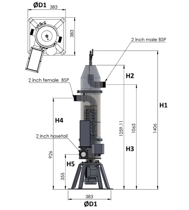
Maximum flow rate through the filter is 18m3/hr. The standard input and outlet size is 2-inch male BSP. Other sizes can be specified ahead of manufacture.
It is fitted with a 100-micron aperture sintered stainless steel screen. The Z200S requires a 5-amp 230v 50Hz electrical supply to drive the unit’s single phase .37 kW motor. Note that the motor only operates the filter system and doers not drive the flow through the filter.
The filter system is controlled by a microprocessor controller in a separate IP65 enclosure to be wall mounted. The enclosure also incorporates a Nastec Pilot load monitor that the feed pump is connected to. The feed pump is controlled by the filter system.
The filter continuously cleans itself and solids backwashed from the filter are forced to the bottom of the vessel where they accumulate.
5.2. Controller and Control Panel
The controller continuously monitors the differential pressure (DP) across the internal self-cleaning filter unit.
The Actuated Valve will open if the differential pressure rises above 40mb. This purges the tank of the filter removing accumulated solids too large to pass through the filter. If the DP rises to 80mb then the system will shut down and the fault light will light up.
The Actuated valve will open once every 60 minutes regardless of differential pressure to ensure that the filter stays clear and runs smoothly.
The control panel screen continuously displays the Differential Pressure reading and the total number of purges since the filter system was last powered up. If there is a fault condition then the display will show “Clean Filter”.
5.3. Dimensions and Characteristics


5.4. Size and Capacity

5.5. Self-cleaning Filter Construction and Materials

6. INTENDED AND UNINTENDED USE
WARNING
Failure to respect the prescribed limits constitutes a situation of use that is technically improper and may endanger the safety of persons and thus EXEMPTS ROTORFLUSH FILTERS LTD FROM ANY RESPONSIBILITY IN THE EVENT OF ACCIDENTS TO PERSONS OR DAMAGE TO EQUIPMENT OR PROPERTY AND/OR TO THE FILTER, THEREBY RENDERING THE GUARANTEE INVALID.
6.1. Intended Conditions of Use
Rotorflush Filters are suitable for filtering water with low levels of suspended solids; Oily/fatty/sticky solids will reduce filter performance.
6.2. Unintended Conditions of Use
Rotorflush self-cleaning filters MUST NOT BE USED for filtering water containing acids and corrosive liquids in general, or in water with temperatures over 60°C, or for filtering inflammable liquids or dangerous liquids in general.
7. HANDLING AND TRANSPORT
7.1. Unpacking and handling
Move the pallet / box containing the filter to the site where it is to be installed
before unpacking.
Check that there are no breakages or dents in the packing; if there are, point this out immediately to the person who delivers the unit.
Carefully remove any packing material around the outside of the filter. While it is still resting on the pallet, check that there has been no damage to the filter during transport, paying particular attention to the filter mesh.
If there is any damage contact Rotorflush Filters Ltd for advice
If no damage is observed the filter can now be lifted off the base of the pallet. This must be done by attaching suitable chains or lifting gear and slowly lifting the filter with a suitable lifting device.
8. INSTALLATION
BEFORE CARRYING OUT ANY INSTALLATION OPERATIONS:
Ensure that all relevant safety procedures are observed. Particular care should be taken when moving the filter. The filter is heavy and only persons experienced and suitably qualified must attempt installation.
8.1. Features and Operation

8.2. Positioning the Filter
The filter system is designed to stand on a hard level surface. The filter can be connected using flexible or solid pipe when standing.
The Z200S MUST be installed vertically with the motor at the bottom and air release valve at the top.
The filter system should be protected from the weather and enough space should be allowed around and above it to access the system for maintenance.
It is very important that the detritus purged from the from the filter is collected appropriately.
8.3. Pipe Connections and setup
Connect the supply of water to be filtered to the 2-inch intake as shown in Fig 3 labelled ‘Dirty water intake’. This is a 2” BSP male threaded connection and connects to the output of your feed pump.
Connect a pipe to the filtered water output connection as shown in Fig 3 labelled ‘Filtered water out’. It is recommended that a valve be fitted on the filtered water output to enable the output to be varied. The valve can be partially closed to reduce the flow rate through the filter if the solids level in the dirty water is too high for the filter to manage at full flow.
The waste outlet should be connected to a pipe taking the waste to drain.
8.4. Electrical Connection
A qualified electrician must connect the unit to the electrical supply. The unit must be protected by a residual current device.
It is very important that the unit is earthed.
Connect the mains cable from the control box to a 230v 50hz supply to the left-hand terminals as shown. An isolator should be provided to enable it to be switched off the system.
A 5amp fuse must be provided to protect the system.
The pump feeding the filter system must have a separate supply connected to the Nastec control panel. See separate instructions below for Nastec Control panel.
8.5. Commissioning
Fill the pipe from the pump intake to the filter with water and prime your main pump.
Check that it is safe to start the pump.
Switch the filter on and then press the green button on the Nastec control panel to start the feed pump. Check in the sight glass that the vessel is filling with water.
Each time the Filter system is switched on it will go through a cycle where it turns the filter system and feed pump on for 10 secs and off for 5 secs, three times and then continues to run. This is to ensure that the cleaning impeller purges air from the system.
Note the Differential Pressure on the screen. It would normally be reading from 0-25mbs depending on the flow rate and level of solids in the water.
If the system goes into fault partially close the valve on the outlet and press the reset button on the control panel. If it continues to run then the valve can be opened again.
9. MAINTENANCE AND REPAIRS
BEFORE CARRYING OUT ANY MAINTENANCE OPERATIONS:
Turn off main pump and make sure that all relevant safety procedures are observed.
Particular care should be taken when uninstalling the filter. The filter is heavy and only persons experienced and suitably qualified must attempt to lift it.
9.1. Changing the Filter Element
The Filter system is supplied with two filter elements. Over time detritus can build up in the pores of the filter mesh that the cleaning system is unable to remove. The filter element can be removed and the spare filter element fitted.

With reference to Fig 4 above follow these steps:
- Disconnect the dirty water feed pipe.
- Undo the quick release coupling and lift off the top cone and remove gasket.
- Undo Filter quick release coupling, pull up the filter element, being careful to remove gasket.
- Re-install spare filter element, lining up quick release coupling and reinstalling gasket.
- Reinstall top cone with gasket and quick release coupling.
- Tighten quick release coupling, this may need use of mole grips or similar to tighten.
9.2. Cleaning the Filter Element
A pressure washer is the best way to clean the filter screen.
The mesh is strong and high-pressure jets should not damage it. Use the lance of the pressure
washer on the outside of the mesh.
It is important that the screen is thoroughly cleaned so that any detritus trapped in the small
pores of the mesh is removed.
9.3. Trouble Shooting

10. WIRING DIAGRAM
[insert wiring diagrams HERE]
11. WIRING SCHEDULE
[insert wiring diagrams HERE]
12. WASTE DISPOSAL
See 6.5 above for materials of construction. Remove rubber ‘O’ rings and motor. Dispose of/recycle safely.
The remainder of the filter is 304/316 Stainless Steel and ABS which can be recycled.
13. WARRANTY
The warranty period is 12 months from delivery.
13.1. Supply of spare parts.
Spare parts will be delivered without charge, within the warranty period, to mainland UK addresses only.
If the customer exports the filter outside the United Kingdom there will be a charge for delivery of the spare parts.
13.2. Return of Filter to Rotorflush Filters Ltd.
If within the warranty period the customer returns the Filter(s), to Rotorflush Filters Ltd then Rotorflush will undertake repairs without charge.
Rotorflush will deliver the repaired filter without charge within the warranty period to mainland UK addresses only.
If the customer exports the filter outside the United Kingdom, there will be charge to return the filter to the customer.
14. NOTES
15. NASTEC CONTROL PANEL INSTRUCTIONS
rotorflush-zircon-z200s-automatic-inline-filter-instruction-manual-v20