
![]()
NE 4422
ASSEMBLY INSTRUCTIONS
IMPORTANT!
Please make sure all lumber, hardware and accessory parts are accounted for. If you are missing anything, please to the store where purchased. Please call our Customer Service Department at the number below.
To register your product visit
Other benefits include information on product warranties, assembly plan updates, joining our mailing list for new products and promotions, receiving our newsletter, and providing feedback on products.
Swing·N·Slide · 1212 Barberry Drive · Janesville, Wisconsin 53545
1-800-888-1232
Observing the following statements and warnings reduces the likelihood of serious or fatal injury
Installation Safety Have You:
- Consulted the assembly instructions supplied with your particular model?
- Noted this accessory is to be used only on Swing·N·Slide approved designs? (Do not alter its design or add/remove components.)
- Made sure all hardware is tightened securely? (Supplied bolt covers must also be fastened securely.)
- Using a hacksaw, cut off all protruding threaded ends of bolts and other fasteners and remove any sharp edges with a metal file as needed, and coated fastener ends with lead free paint?
- Placed the equipment on level ground, not less than six feet (1.8 meters) from any structure or obstruction such as a fence, garage, house, overhanging branches, laundry lines, or electrical wires?
- Made sure home playground equipment is not installed over concrete, asphalt, packed earth or any other hard surface? (A fall onto a hard surface can result in serious injury to the equipment user.)
- Verified that suspended climbing ropes, chain,or cable are securely anchored at both ends and cannot be looped back unpon itself?
- Consulted in assembly instructions of your particular model for minimum use zones?
- Used a water sealant on your play set to protect the wood and prevent cracking and warping?
- Followed all anchoring and shock absorbing surfacing requirements on the back of this sheet as they apply?
- Made sure not to allow children to use equipment until it is properly installed?
- Made sure to adjust all swings so there is a minimum 8” clearance between the swing and the ground surface?
Operating Safety Have You:
- Determined that on-site adult supervision is provided for children of all ages?
- Warned children the following before allowing them to use the equipment?
- Not to walk close to, in front of, behind or between moving items.
- Not to twist swing or any other accessory chains or ropes or loop them over the top support bar since this will reduce the strength of chain or rope.
- Not to swing empty seats or other accessories.
- Not to slide down swing chains.
- Be sure to sit in the center of the swing seat and other accessories with full weight on the seat.
- Not to attach items to the playground equipment that are not specifically designed for use with the equipment such as but not limited to, jump ropes, clotheslines, pet leashes, cables and chain. They may cause a strangulation hazard.
- Not to climb or walk on the top of swing beams, railings or roof.
- Not to use equipment in a manner other than intended.
- Not to get off equipment while it is in motion.
- Not to climb on the equipment when it is wet.
- Be sure to go down slides feet first.
- Determined that only one child per planned occupant seat should be allowed on this set at one time.
- Determined children must be dressed appropriately for play. Avoid hooded jackets, bicycle or other sports helmets, clothing with draw strings and loose fitting clothes which could become entangled or snagged on equipment.
- Determined that suspended climbing ropes, chain, or cable are securely anchored at both ends and cannot be looped back upon itself.
- Made certain the slide is placed so that is is not in direct sunlight.
Safety Maintenance – Follow these preventive maintenance instructions at the intervals required:
- To prevent the deterioration of materials, remove plastic swing seats and other plastic accessories when outdoors temp dips down to or below 32° F and take indoors. Reinstall these plastic elements at the beginning of each play season.
- At the beginning of each play season check metal parts for rust. If found, sand and repaint using a non lead-based paint meeting the requirements of 16 CFR 1303 or SOR/2005-109.
- At the beginning of each play season and once a month during each play season, check all moving parts for wear, rust or other deterioration. Replace as needed. If any of these conditions exist, call 1-800-888-1232 to order replacement accessories.
- At the beginning of each play season and once a month during each play season lubricate metallic moving parts.
- At the beginning of each play season and twice a month during each play season, check all protective coverings on bolts, pipes, edges, and corners. Replace if they are loose, cracked, or missing.
- At the beginning of each play season and twice a month during each play season, rake and check depth of loose fill protective surfacing material to prevent compaction and maintain appropriate depth. Replace as necessary.
- At the beginning of each play season and twice a month during each play season tighten all hardware.
- At the beginning of each play season and twice a month during each play season, check all wood members for deterioration and splinters. Sand down splinters and replace deteriorating wood members.
Disposal Instructions
When the equipment is taken out of service, it must be disassembled and disposed of in such a way that no unreasonable hazards will exist at the time the set is discarded.
Important! Additional Safety Instructions for all Swing-N-Slide Playground Equipment.
Save this instruction sheet in the event the manufacturer needs to be contacted.
2
This product is intended for single family home/residential use only and not intended for use in any public setting. Placement in any public setting constitutes a misuse of this product.
IMPORTANT!
ADDITIONAL REQUIRED SAFETY INSTALLATION INSTRUCTIONS
According to ASTM requirements, all kits must be anchored to the ground and, if the unit has a climbing rope, the rope end must be anchored to the ground. If soil conditions permit stakes to be pulled out easily, cementing into ground is necessary.
- To anchor the unit to the ground, Follow the instructions included in this plan for applying Anchor-It devices to your unit, or use 2″ x 4″ x 18″ (45mm x 95mm x 457mm) pressure-treated stakes. Pound stakes into ground at least 12″ (305mm) at all inside corners of the posts (including A-frame legs and climbing unit posts). Attach with four (4) 16D (3-1/2″) galvanized nails per stake into each tower and/or A-frame upright.
- If the unit has a climbing rope, securely anchor the rope at both ends.
- Once the unit is completely assembled and before children are allowed to play on it, proper shock-absorbing surfacing material must be installed. This may be accomplished by using loose-fill materials at a sufficient depth. The Consumer Product Safety Commission “Handbook for Public Playground Safety” lists the following materials and required depths that are sufficient for home/residential application. Supplemental information may be found in ASTM F1292. For fall height protection up to 9 ft. (2.742m) [recommended for Swing·N·Slide kits]:
LOOSE FILL MATERIAL REQUIRED (UNCOMPRESSED) DEPTH1in. (mm)
Wood Mulch 9″ (229mm)
Double Shredded Bark Mulch 9″ (229mm)
Uniform Wood Chips 12″ (305mm)
These depths were derived from the CPSC Handbook. Swing·N·Slide has not done independent tests to determine these required depths.
When properly installed, shock absorbing material will completely cover the horizontal baseboards on climbing units. This protective surfacing must extend a minimum of 6 ft. (1.828m) in all directions from the perimeter of the equipment or from the outermost edges of any component. For example, a slide extending beyond the platform must have protective surfacing at least 6 ft. (1.828mm) out from both sides as well as the end. For swings, the protective surface must extend at least 14 ft. (6m) out from both the back and front of the swing when the swing is in its rest position.
For further information on playground safety,
Swing-N-Slide® takes great pride in the quality and durability of our products. Our Manufacturer’s Limited Warranty provides confidence and demonstrates our commitment to providing quality residential playground products.
MANUFACTURER’S LIFETIME LIMITED WARRANTY
Swing-N-Slide® warrants its thermoformed slides and climbing mountains to be free from defects in workmanship and materials, under normal use and conditions, for the lifetime of the product.
MANUFACTURER’S 5 YEAR LIMITED WARRANTY
Swing-N-Slide® warrants its Custom Ready-to-Build Play Set kits and accessories to be free from defects in workmanship and materials, under normal use and conditions, for a period of 5 years.
MANUFACTURER’S 5 YEAR LIMITED WARRANTY
Swing-N-Slide® warrants its No-Cut and Wood Complete Ready-to-Assemble Play Set kits against wood rot and termite damage, and to be free from defects in workmanship and materials, under normal use and conditions, for a period of 5 years for structural wood components.
Cosmetic defects that do not affect the structural integrity of the product, or natural defects of wood such as warping, splitting, checking, twisting, shrinkage, swelling or any other physical properties of wood that do not present a safety hazard, are not covered by this warranty.
MANUFACTURER’S ONE YEAR WARRANTY
Swing-N-Slide® warrants its canopy roofs and/or tarps, and Timber GLOVE lumber wrap to be free from defects in workmanship and materials, under normal use and conditions, for a period of one year.
Swing-N-Slide® will repair, or at its discretion, replace any part within the stated warranty period which is defective in workmanship or materials. This decision is subject to verification of the defect upon delivery of the defective part to Swing-N-Slide® at 1212 Barberry Drive, Janesville, Wisconsin, 53545. Any part(s) returned to Swing-N-Slide® must have prior approved Return Authorization Number and proof of purchase, including the date of purchase. This
warranty is valid only if the product is used for the purpose for which it was designed and installed at a residential, single family dwelling. This warranty is void if the product is put to commercial or institutional use. This warranty does not cover (a) products which have been damaged by acts of Nature, negligence, misuse, or accident, or which have been modified or repaired by unauthorized persons; (b) the cost of labor; or the cost of shipping the product, any part, or any replacement product or part.
Swing-N-Slide® DISCLAIMS ALL OTHER REPRESENTATIONS AND WARRANTIES OF ANY KIND, EXPRESS, IMPLIED, STATUTORY OR OTHERWISE, INCLUDING THE IMPLIED WARRANTIES OF MERCHANTIBILITY AND FITNESS FOR A PARTICULAR PURPOSE. Swing-N-Slide® WILL NOT BE LIABLE FOR ANY INCIDENTAL OR CONSEQUENTIAL DAMAGES. This warranty is non-transferable and does not extend to the owners of the product subsequent to the original purchaser. Some states do not allow limitations on implied warranties or exclusion of incidental or consequential damages, so these restrictions may not be applicable to you. This warranty gives you specific legal rights. You may also have other rights, which vary from state to state.
This warranty also does not apply to:
- Structures not erected, maintained or inspected in conformance with Swing-N-Slide® installation plans
- Structures that have had parts added or substituted not in conformance with Swing-N-Slide® installation plans
- Parts that have been modified, altered or misused
- Parts that have not been used as designed or intended
- Damage due to acts of Nature, vandalism, abnormal use or abuse as determined by Swing-N-Slide®
3
TOOLS REQUIRED


ELECTRIC DRILL 1/2″ SOCKET & WRENCH


HAMMER WRENCH
SCREWDRIVER TAPE MEASURE

CIRCULAR SAW CARPENTER’S SQUARE
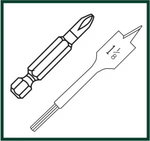
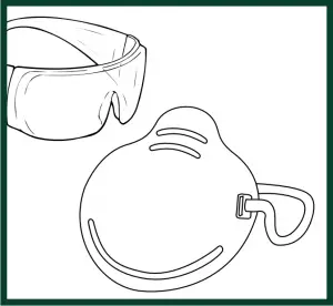
PHILLIPS BIT 1-1/8″ SPADE BIT SAFETY GLASSES & DUST MASK
KIT COMPONENTS
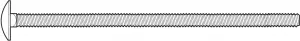

(4) 5-1/2″ carriage bolts (4) 5/16″ flat washers
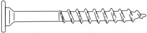

(16) 2″ Lag Screw (6) T-nuts
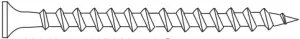

(139) 2-1/2″ Wood Screw (4) loc nuts
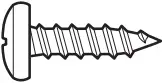

(2) 1/2″ panhead screws (1) 3/8″ Drill Bit (6″ Min.)
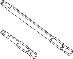
(1) T20 Torx® Bit, (1) T30 Torx® Bit (6) beam clamps (slotted)
NOTE: Unless indicated otherwise, all hardware is shown actual size.
8
KIT COMPONENTS
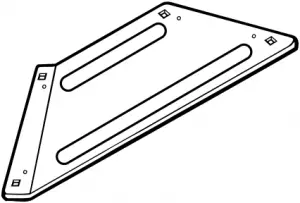
(2) Left EZ Frame Braces (6) Swing Hangers
(2) Right EZ Frame Braces

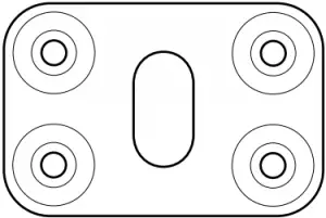
(4) beam covers (4) EZ Frame Brackets


(2) Sling Seats (4) Quick Link

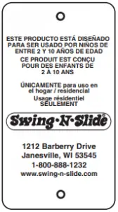
(4) 58’’ Coated Chain (1) Name Plate
(2) Swing Seat
weight limit: 115 lbs.

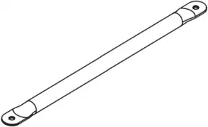
(1) Plan (1) Trapeze Bar

(2) Rings (4) Quick Link
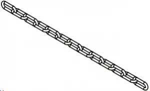
(2) 33″ Uncoated Chain
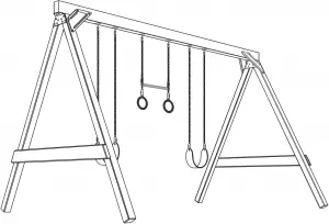
(1) Ring/Trapeze Combo Swing
weight limit: 115 lbs
9

PROJECTS 135, 143. 162
No. of Children: Up to 5
Min. Use Zone: 24′ x 28′
Set Dim. 8’W x 12’L x 8’H
Est. Building Time: 4-6 hr.

PROJECT 156
No. of Children: Up to 6
Min. Use Zone: 28′ x 28′
Set Dim. 8’W x 16’L x 8’H
Est. Building Time: 4-6 hr.
Materials Required
PROJECTS 135, 143, 162
(1) 2″ x 4″ x 8′
(2) 2″ x 6″ x 8′
(4) 4″ x 4″ x 8′
(1) 4″ x 6″ x 12′ or
(2) 2″ x 6″ x 12′
PROJECT 156
(1) 4″ x 6″ x 16′ or
(2) 2″ x 6″ x 16′

(1) 2″ x 4″ x 8′

(4) 4″ x 4″ x 8′

(2) 2″ x 6″ x 8′ Use EZ Frame Bracket as angle guide
(1) 4″ x 6″ x 12′ or (2) 2″ x 6″ x 12′ – Project 135, 143, 162

(1) 4″ x 6″ x 16′ or (2) 2″ x 6″ x 16′ – Project 156
10
ASSEMBLY INSTRUCTIONS
Fig. 1 NOTE: Lay the lumber on a flat surface before beginning laminated beam assembly.
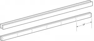
- If 4″ x 6″ lumber is not available, you may laminate two 2″ x 6″ pieces of lumber together to create the beam.
- To make a laminated beam, use two 2″ x 6″ x 12′ pieces of lumber.
- Lay the lumber on a flat surface and align all of the edges. NOTE: Make sure each piece of lumber is the same length.
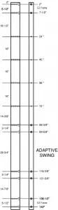
- Starting at the ends of the board, measure and place a mark on the boards at 24″ intervals (Fig. 1).
- Assemble the beam by screwing each end together using three 2-1/2″ screws. NOTE: Stagger the screws as shown in Fig. 1 to insure a sturdy bond. Repeat every 24″ along the entire length of the beam. When beam is complete, measure, drill holes and attach nylon bushing swing hangers according to the instructions.
11
ASSEMBLY INSTRUCTIONS
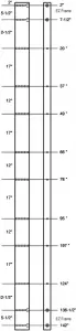
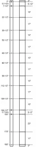
PROJECTS 135, 143 PROJECT 162 PROJECT 156
12′ Beam 12′ Beam 16′ Beam
12
T-nut/Tuerca en

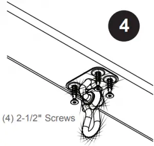
2-1/2″ Screw
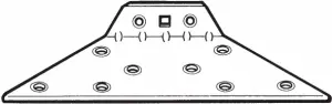
- Measure and mark all holes centered on the 4″ surface of the beam as indicated in (Fig. 2). Using a 3/8″ drill bit, drill holes through the beam at a 90° angle to the lumber. Turn the beam over and counterbore each hole for EZ Frame Bracket with a 1-1/8″ spade bit approximately 5/8″ deep at locations shown in fig. 2.
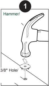
- Tap T-nut into 3/8″‘ hole as shown in (1). approximately 5/8″ deep
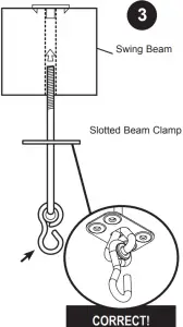
- Place a slotted beam clamp over the swing hanger as shown in (2).
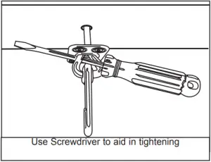
- Insert the swing hanger into the beam and thread it into the T-nut until it is flush or near flush with the top of the T-nut. A screwdriver may be used to twist the hanger, as shown in (3).
- Orient swing hanger as shown in (4). Use (4) 2-1/2″ screws to secure beam clamp.
- Check hanger to ensure it does not spin.
- Repeat for all swing hangers. NOTE: Enough swing hangers and clamps are provided for included accessories. One accessory area will be open. NOTE: Adaptive Swing not included, please visit swing-n-slide.com to find a retailer near you.
13
ASSEMBLY INSTRUCTIONS
Fig. 4

Fig. 5
14
KIT COMPONENTS
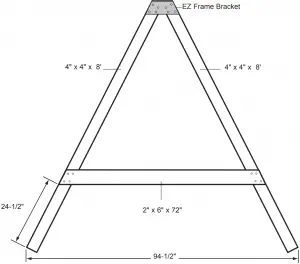
- Measure the 4″ x 4″ x 8′ legs to insure they are the same length. Adjust if necessary. Lay two 4″ x 4″ x 8′ legs on a level surface with ends together to form a “V”. Place EZ frame bracket on leg ends and position so the legs and bracket edges line up (Fig. 4).
- Measure the base of the A-Frame from the outermost points. The legs should be approximately 94-1/2″ apart (Fig. 5).
- Secure the EZ Frame Bracket to the 4″ x 4″ using eight 2-1/2″ screws per bracket. Be careful to maintain the alignment of the bracket to the edges of the 4″ x 4″s.
- Place the 2″ x 6″ x 72″ cross member on the A-Frame assembly. The bottom edge of the cross member should be approximately 24-1/2″ from the bottom of the outside edge of the 4″ x 4″ (Fig. 5). Cross member edges should be flush with the frame legs. Attach the 2″ x 6″ x 72″ cross member to the frame assembly using four 2-1/2″ screws at each joint (8 per board).
- Turn the A-Frame over and add an EZ Frame Bracket to the other side. Repeat these steps to complete a second frame (two frames are required).
15
ASSEMBLY INSTRUCTIONS
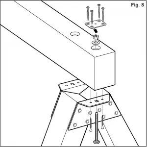
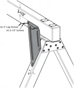
Fig. 7 Fig. 8
(4) 2″ Lag Screws
AND
(4) 2-1/2″ wood screws per Brace
(2) Brace per side of unit
Fig. 9
16
KIT COMPONENTS
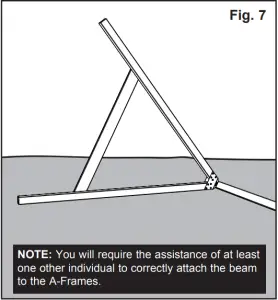
- Place the beam on the ground and align A-frame brackets with the corresponding holes of the beam (Fig. 7). Insert a 5-1/2″ carriage bolt through the hole of the bracket and through the beam. NOTE: It may be necessary to force the carriage bolt through the beam with the aid of a hammer. Secure using a washer and loc nut. Secure brackets using one 2-1/2″ screw on each side of the carriage bolt (Fig. 8). Center the beam covers over the counterbored holes and attach using four 2-1/2″ screws as shown. Repeat step 1 to attach second frame to the beam.
- Working with one brace at a time, position brace to frame 2-1/2″ from the top of the beam and 1″ from the side of the leg. Make sure the A-frame is 90° to the beam. Attach the brace to the frame and beam using four 2-1/2″ screws. (Fig 9.)
- Secure Brace in place with (4) 2″ Lag Screws. Repeat for remaining (3) Braces.
17
ASSEMBLY INSTRUCTIONS
x2 Per Swing
Fig. 10 Fig. 11
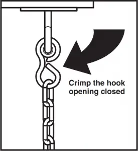
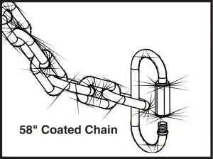
Fig. 12
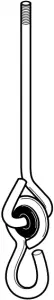
- Hang the chains from the nylon bushing swing hangers. Crimp the hook opening closed with pliers to secure the chains to the swing hangers (Fig. 10). Make sure all connections are tightly crimped and secure before using Sling Swings.
- Take one length of chain and place the last link of chain through the Quick Link as shown (Fig. 11).
- Place the Quick Link through the Grommet of the Sling Swing as shown (Fig. 12).
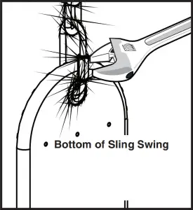
- Tighten the threaded sleeve of the Quick Link with a suitably sized wrench so that the seat is securely attached and the Quick Link cannot be easily loosened (Fig. 12). Repeat for second chain, Quick Link, and Sling Swing Grommet.

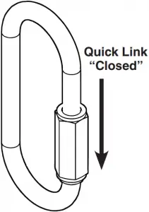
NOTE: For correct installation, the thread must be at the bottom.
18
ASSEMBLY INSTRUCTIONS
x2 Per Swing
Fig. 10 Fig. 13


Fig. 14 Fig. 15 Fig. 16


- Attach Quick Link to chain oriented as shown (Fig. 13).
- Attach Quick Link to gym ring as shown (Fig. 14). Attach second set of Quick Links (3) links up. Attach Trapeze Bar as shown (Fig. 15).
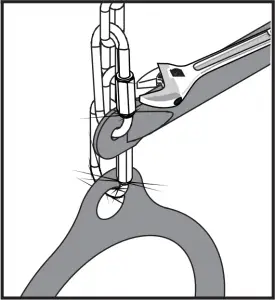
- Tighten all Quick Links closed with wrench (Fig. 16).
- When hanging accessories next to other components, a minimum clearance of at least 8″ from adjacent swinging elements or any play equipment support structure is required.
- Hang the chains from the Swing Hangers. Crimp the hook opening closed with pliers to secure the chains to the swing hangers (Fig.10). Make sure all connections are closed tightly and secure before using.
19
KIT COMPONENTS
Fig. 17
Note: Once installed, there must be a minimum 8″ clearance between the bottom of the swings and the surfacing.
Staking
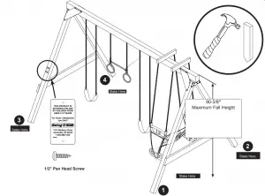
- Position four 18″ stakes as indicated in Fig. 17. NOTE: Place the stakes next to the outside of the A-frame legs and the backside of the ladder corner post. Pound the stakes into the ground, leaving 5-1/2″ of the stake above ground. Secure the stakes to the posts using four 2-1/2″ screws per stake.
- Secure your product ID tag onto easy to read location of vertical upright using (2) 1/2″ Pan Head screws as shown in Fig. 17.
20
Questions???…
![]()
© Swing-N-Slide 2015 Printed In China LA 7493