SWISHER 60″ Fast Finish Trail Mower Owner’s Manual

LIMITED WARRANTY
The manufacturer’s warranty to the original consumer purchaser is: This product is free from defects in materials and workmanship for the period’s shown below beginning from the date of purchase by the original consumer purchaser. We will repair or replace, at our discretion, parts found to be defective due to materials or workmanship. This warranty is subject to the
following limitations and exclusions:
As required by CFR § 1060.120, the fuel system related components, which have been certified to this equipment by SAI are to be free of defects in material and workmanship for a period of two (2) years from the date of purchase by the original consumer purchaser.
- Engine Warranty
All engines utilized on our products have a separate warranty extended to them by the individual engine manufacturer. Any engine service warranty is the responsibility of the engine manufacturer and in no way is Swisher or its agents responsible for the engine warranty. The Kawasaki Engine Service Hotline is 1-877-364-6404 or email [email protected] - Commercial Use
This product has a 1yr Limited Commercial – 2 Year Limited Consumer on All Non-Engine Parts from the date of purchase.
- Limitations
This warranty applies only to products, which have been properly assembled, adjusted, and operated in accordance with the instructions contained within this manual. This warranty does not apply to any product of Swisher that has been subject to alteration, misuse, abuse, improper assembly or installation, shipping damage, or to normal wear of the product. - Exclusions
Excluded from this warranty are normal wear, normal adjustments, and normal maintenance.
In the event you have a claim under this warranty, you must return the product to an authorized service dealer. All transportation charges, damage, or loss incurred during transportation of parts submitted for replacement or repair under this warranty shall be borne by the purchaser. Should you have any questions concerning this warranty, please contact us toll-free at 1-800-222-8183. The model number, serial number, date of purchase, and the name of the authorized Swisher dealer from whom you purchased the mower will be needed
before any warranty claim can be processed.
THIS WARRANTY DOES NOT APPLY TO ANY INCIDENTAL OR CONSEQUENTIAL DAMAGES AND ANY IMPLIED WARRANTIES ARE LIMITED TO THE SAME TIME PERIODS STATED HEREIN FOR ALL EXPRESSED WARRANTIES. Some states do not allow the limitation of consequential damages or limitations on how long an implied warranty
may last, so the above limitations or exclusions may not apply to you. This warranty gives you specific legal rights and you may have other rights, which vary from state-to-state. This is a limited warranty as defined by the Magnuson-Moss Act of 1975.
SAFETY PRECAUTIONS
 This Safety Alert Symbol indicates important messages in this manual. When you see this symbol, carefully read the message that follows and be alert to the possibility of personal injury.
Read this manual completely. This machine can amputate hands, feet, and throw objects. Failure to observe the following safety instructions could result in serious injury or death.
- Read the manual. Learn to operate this machine safely.
- Always disconnect the spark plug wire and place the wire where it cannot contact the spark plug, to prevent accidental starting the engine when setting up, transporting, adjusting or making repairs.
- Keep all shields and guards in place.
- Understand the speed, steering and stability of this machine. Know the positions and operations of all controls before you operate this machine. Check all of the controls in a safe area before starting to work with this machine.
- Allow only responsible adults who are familiar with these instructions to operate this machine. Never allow children to operate this machine.
- Clear the area of objects such as rocks, toys, wire, etc. that can be picked up and thrown by the blade.
- Be sure the area is clear of other people before mowing. Be aware of the mower discharge direction and do not point at anyone. Stop the machine if anyone enters the mowing area. Children are often attracted to the machine and the mowing activity. Never assume that children will remain where you last saw them. Keep children under the watchful care of another responsible adult.
- No riders!
- Do not put hands or feet near or under rotating parts. Keep clear of the discharge opening at all times.
- Do not mow in reverse. Always look down and behind before and while backing.
- Turn off the blades when not mowing. Before leaving the machine, turn off the blades and stop the engine
- Watch for traffic when operating near or crossing roadways.
- Do not operate the mower if it has been dropped or damaged in any manner or if the mower vibrates excessively. Excessive vibration is an indication of damage. Repair mower as necessary.
- Dress properly. Do not operate the mower when barefoot or wearing open sandals. Wear only solid shoes with good traction when mowing.
- Do not operate the machine while under the influence of alcohol or drugs.
- Do not operate on slopes greater than 15 degrees. Never tamper with safety devices. Check their proper operation regularly.
- Stop and inspect the equipment if you strike an object. Repair, if necessary, before restarting.
- Never make adjustments or repairs with the engine running.
SAFETY DECALS
Replace decals immediately if damaged. Order by part number from Swisher.
- OD45- Warning Decal AVOID SERIOUS INJURY OR DEATH

- Read and follow owner’s manual.
- Keep hands and feet away from discharge area and blades.
- Avoid sudden turns, sudden changes in direction, sudden changes in speed.
- Go up and down slopes, not across.
- If machine stops going uphill, stop blade and back slowly down.
- Look down and behind before and while moving backwards.
- Do not operate when children or others are around.
- Never carry children or others as passengers.
- Keep safety devices, such as guards and deflectors, in place and operating.
- Remove objects that could be thrown by the blade.
- Know safe operating instructions before starting engine.
- OD55- Triangle Danger Decal

- Keep Hands and Feet away.
- OD11- No step Decal

Caution Unstable Surface No step - OD43- Flying Debris Decal
- WARNING

- FLYING DEBRIS EYE INJURY AND/OR CUTS POSSIBLE.
- KEEP PEOPLE CLEAR OF AREA WHEN MOWING.
- USE CHUTE GUARD/COVER OR COMPLETE GRASS CATCHER WHEN MOWING.
- DEBRIS MAY CAUSE INJURY
- OD33- Speed Decal

- Caution Do not exceed 5 MPH.
- OD29- Danger Decal

- Danger Spinning Blades
- Keep clear
- Contact can injure
REQUIRED ASSEMBLY
FRONT WHEEL CASTER ASSEMBL
- Remove single nut and washers from caster shaft.
- Place one washer (NB195) on the shaft of the caster/wheel subassembly.
- Slide same shaft through the bearing/frame with wheel towards the ground.
- Place the other washer (NB195) on the shaft; it should be resting on the top bearing.
- Add thin washer (17×195).
- Thread nyloc jam nut onto shaft.
- Tighten nut snuggly, making sure shaft threads enter the nyloc of the nut. Over-tightening of this nut will bind caster.
- Repeat process for other front side.
- Push on plastic dust covers over nut and thin washer until it snaps into place.
REAR WHEEL ASSEMBLY
- Remove cotter pin from axle and remove thin washer (NB149) from axle. Leave two NB178 washers on axle.
- If necessary (to take up space) slide extra washer (NB178) over axle, then wheel (with valve stem out).
- Slide on washer (NB149) and replace cotter pin in end of axle.
- Bend cotter pin so it will not fall out.
- Repeat process for other wheel.
OFFSET & CENTER TOW HITCH BAR ASSEMBLY
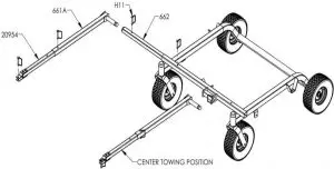
- Lay out parts according to the diagram.
- Insert part 661A into part 662 and pin with the hitch pin (H11).
- Insert part 20954 into part 661A. Choose from the 3 holes to set the desired hitch length.
Pin with a hitch pin (H11). - Part 662 slides into the front tube of the frame. Again, choose from the 3 holes to arrange desired offset. Pin with a hitch pin (H11).
- Eliminate step 2 for hitching from the center bracket. Only one method can be used at a time
A U1 battery is required (not included). Position battery hold down bracket as shown. Tighten nuts so battery will not shift position.
Battery Mounting Detail
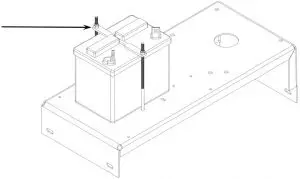
A U1 battery is required (not included). Position battery hold down bracket as shown. Tighten nuts so battery will not shift position.
*Battery cover not shown
OPERATING YOUR TRAIL MOWER
 The operation of any mower can produce foreign objects to be thrown into the eyes, resulting in severe eye damage. Always wear certified safety glasses or wide vision safety goggles over spectacles before starting any cutting machine and while operating such a machine.
 The operation of any cutter produces sound waves that are damaging to the human ear. Ear protection is recommended.
Tragic accidents can occur if the operator is not alert to the presence of children. Children are often attracted to the machine and the mowing activity. Never assume that children will remain where you last saw them.
INTENDED USE
This Trail Mower is designed to produce a quality finish cut on lawns, golf courses, etc. It is not designed to clear brush or cut saplings. Your Trail Mower should be towed behind an ATV, a golf cart, lawn tractor, or similar approved vehicle. It is not meant for speeds exceeding 5 mph
ATTACHING TRAIL MOWER TO TOW VEHICLE
- Place mower behind vehicle and back vehicle up to desired attaching position.
- When offsetting Trail Mower do so to side opposite the discharge of the tow vehicle.
- Attach tow hitch (661) to the swivel hitch with hitch pin (H11). Make certain hitch pin goes completely through each piece and is clipped to prevent accidental separation.
- Attach red safety tether (6736) to both the towing vehicle and to the Trail Mower toggle switch (685SP), located on the left battery side cover (17614). Its purpose is to manually stop mower engine or to stop mower engine in case the two machines become separated. (See Motor Base Detail page 14).
- It is extremely important the safety tether is secured properly to both the toggle switch and the towing vehicle.
STARTING THE ENGINE
See engine manufacturer’s instructions for the type and amount of oil and fuel used. Trail Mowers with electric start engines will need a battery (sold separately). Swisher recommends using a standard “U 1 R” lawn & garden battery.
IMPORTANT: This engine is not equipped with a spark arrester muffler. It is a violation of California Public Resource Code Section 4442 to use or operate the engine on any forest-covered, brush-covered, or grass-covered land. Other states or federal areas may have similar laws.
- Engine must be level to accurately check and fill oil. Do not overfill.
- Make sure the tow vehicle parking brake is set, mower is level, and blades are disengaged.
- Check spark plug wire, oil, and fuel.
- Check all electrical connections (See Schematics).
- Make sure toggle switch is turned “ON” and the red tether is properly attached.
- Set engine idle to “CHOKE” position.
- With feet clear of mower deck, turn key switch to the “START” position and release when engine begins to run.
- Set engine idle at desired RPM.
BREAKING IN YOUR MOWER
- Set vehicle parking brake or chock wheels to prevent accidental rolling.
- Start engine properly.
- Slowly, engage blade control.
- In a safe environment, i.e. no children, allow blades to rotate and engine to idle for 5 minutes. This breaks in the belts and the engine.
- Stop mower properly.
SHUT OFF MOWER ENGINE AND REMOVE SPARK PLUG WIRE FROM SPARK PLUG BEFORE MAKING ANY ADJUSTMENTS TO THE MOWER.
MOWER HEIGHT ADJUSTMENT
- Adjust while mower is not running.
- The cutting range is approximately 1” to 5.5”. The height should be measured from the ground to the blade tip without the engine running.
- Rotate height adjust crank handles (H7N) in a clockwise direction to lift the mower deck. A counter-clockwise direction is used to lower the mower deck.
- Make sure the height adjustment is the same at side crank handles. For best results, see “SUGGESTED PRACTICE” section. Graduated scales are for reference only, not the actual cutter height.
- Place crank handle in a retracted position to maintain height adjustment.
STARTING TO MOW
- Adjust the cutting height.
- Double check vehicle to mower attachment.
- Start mower engine properly.
- Slowly, activate the blade engage lever (21929) by rotating it forward and left until the lever locks into place.
- Carefully mount tow vehicle and start mowing slowly.
STOPPING THE MOWING SESSION
- Pull safety tether to shut toggle switch “OFF”. If the engine fails to stop or if the safety tether has become inoperable, then use Alternative Stopping Method.
ALTERNATIVE STOPPING METHOD
- Bring vehicle to complete stop, shut off engine, and set parking brake.
- Disengage blade engage lever (21929).
- Manually shut toggle and key switches to their “OFF” positions.
- Always remember to remove keys to avoid irresponsible usage.
TRANSPORTING MOWER
- Stop mower properly.
- Place mower deck in its highest position.
- If transporting without the use of a tow vehicle, then remove spark plug wire and place where it cannot contact the spark plug.
SUGGESTED MOWING PRACTICES
- Operate mower engine at full throttle to assure the best cutting performance and maximum material discharge.
- Allow wet grass to dry. Clumps of wet grass will collect under the mowing deck.
- Mowing should be started with tow vehicle in low gear and increased only as safe mowing conditions permit. This speed should not exceed 5 mph.
- The average lawn should be cut to approximately 2.5” during the cool season and to over 3” during the hot months.
- For a healthier lawn and better aesthetics, your lawn should be mowed often and after moderate growth.
- When cutting high or dense grass areas go slowly. Some areas may need to be mowed twice. The second cut should be at 90 degrees to the first, if possible.
- Mowing thick or high grass. Raise rear height crank handles to .5”-.75” above the other two handles.
- Creating a manicured lawn. Lower rear height crank handle to .25”-.5” below front of deck. This allows grass blades to be cut twice. It also continually cuts clippings to produce a mulching effect.
GENERAL TROUBLE SHOOTING
- The mower is not cutting level.
- Level deck, making sure the side crank-handles are equal.
- Check air pressure of all tires; make sure they are equal, and to manufactures specifications.
o Examine blades for damage, while mower engine is not running.
- The engine will not start.
- Disengage blades, turn toggle switch to “ON” position, check battery and all other electrical connections, and inspect spark plug and wire.
- Check for fuel in the engine.
- Engine runs poorly.
- See engine manual.
- Check throttle adjuster.
- Replace fuel, clean fuel filter and fuel line.
IF PROBLEMS PERSIST HAVE A QUALIFIED MECHANIC SERVICE THE MOWER. NEVER ATTEMPT TO MAKE AN ADJUSTMENT THAT YOU ARE NOT SURE IS CORRECT. DOING SO CAN CAUSE OTHER PROBLEMS.
MOWER MAINTENANCE
GENERAL RECOMMENDATIONS
The warranty on this Trail Mower does not cover items that have been subjected to operator abuse or negligence.
To receive full value from the warranty, operator must maintain unit as instructed in this manual.
Some adjustments will need to be made periodically to maintain your unit properly.
All adjustments in this manual should be checked at least once each season.
Periodically inspect and clean excessive debris inside the battery cover (17340) and belt covers (18391). Disconnect spark plug wire before cleaning.
BEFORE EACH USE
- Check engine oil level on a level surface. Check twice to insure an accurate reading.
- Check condition of air filter; clean and replace as necessary.
- Check blade operation; keep blades in good condition.
- Check for loose fasteners and tighten them as needed.
AFTER EACH USE
- Keep blades sharp.
- Remove fresh grass clippings with garden hose.
- Grass clippings hardened to the underside should be scraped out with a putty knife.
- Keep fluids at proper levels.
- Cover unit to prevent rain or other debris buildup. Definitely cover the engine.
BEFORE AND/OR AFTER EACH SEASON
- Replace the spark plug.
- Clean or replace the air filter.
- A new spark plug and clean air filter assure proper air-fuel mixture and help your engine run better and last longer.
- Check blades and belts for wear. Replace as necessary.
STORAGE RECOMMENDATIONS
Do not store engine indoors or other poorly ventilated area. Keep engine away from gas appliances where fumes could contact open flame, pilot lights, or sparks
If engine is to be stored for 30 or more days, prepare unit as follows:
- Drain fuel outside into an approved container.
- Start engine properly and run until unit is out of fuel.
- Let engine cool.
- Remove remaining gasoline from carburetor and fuel tank to prevent gum deposits from forming within the engine. Gum deposits can cause malfunction in the engine.
- Store mower with blades disengaged to prevent belts from being permanently stretched.
BLADE CARE AND SERVICE
For best results cutter blades must be kept sharp. The blades can be sharpened with a few strokes of a file or grinding wheel. Do not attempt to sharpen blades while they are on the mower. Disconnect spark plug wire before
servicing unit.
Important: Replace blades that have been damaged or deeply nicked.
Important: Check blade and spindle hardware on a regular basis to make sure nuts are tight.
 Only a qualified mechanic should be used for any adjustments, disassembly or other kind of repairs.
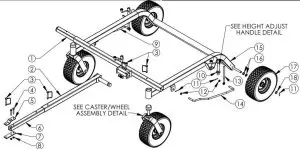
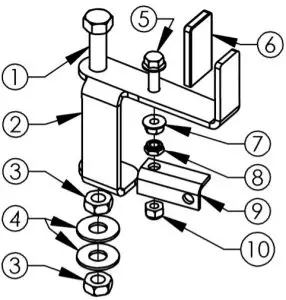
Frame Assembly
| ITEM # | QTY. | PART NO. | DESCRIPTION | ITEM # | QTY. | PART NO. | DESCRIPTION |
| 1 | 1 | 662* | Weldment – Tongue Offset Extension | 10 | 3 | 10579 | Bushing -Stepped Height Adjust |
| 2 | 1 | 661A* | Weldment – Solid Stock Hitch | 11 | 6 | NB126 | Pin – 1/8″ X 1″ Cotter |
| 3 | 4 | H11 | Pin – Safety Hitch | 12 | 4 | T2PB | Bushing – Plastic |
| 4 | 2 | NB622 | Bolt – Serr Flange, 5/16-18X2 1/4 | 13 | 3 | 10038 | Bolt – Eye |
| 5 | 1 | 21152* | Plate – Clevis, Top | 14 | 1 | 3665 | Bar – Left Sway |
| 6 | 1 | 20953* | Tube – Tow Hitch | 15 | 1 | 17600* | Weldment – T60 Frame |
| 7 | 1 | 21153* | Plate – Clevis, Bottom | 16 | 4 | NB178 | Washer – 5/8 ID X 1 OD 10 GA |
| 8 | 2 | NB170 | Nut – Serr Flange 5/16-18 | 17 | 2 | F4157WK | Wheel/Tire |
| 9 | 1 | 3664 | Bar – Right Sway | 18 | 2 | NB149 | Washer – 5/8 ID X 1 OD 14 GA |
ITEMS 4-8 ARE PART OF ASSEMBLY 20954
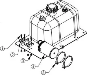
Gas Tank Assembly Detail
| Parts Not Shown | |
| Part # | Description |
| 11782 | Line – Fuel, Bulk, 1/4″ Low Perm |
| 18232 | Line – Fuel, Bulk, 3/16″ Low Perm |
| 18223 | Clamp – Fuel |
| AS021 | Tie, Black 5 1/2″ |
| Item # | Qty | Description | Part # |
| 1 | 4 | Nut – Nyloc 3/8-16 ZY | NB182 |
| 2 | 1 | Mount – For EPA/CARB Gas Tank | 18331* |
| 3 | 2 | Ubolt – SQ , 3/8-16X2.437 X 3 Lg GR 5 ZY | 12447 |
| 4 | 1 | Cap, Fuel – 2.50 Gallon, Carb Sealed | 18221 |
| 5 | 1 | Bracket – Fuel Tank | 18225 |
| 6 | 2 | Bolt – Serr Flange 1/4-20 X 1 3/4 GR5 ZY | 18236 |
| 7 | 1 | Fuel Tank – 2.5 Gallon, Carb | 18214 |
| 8 | 2 | Washer – SAE Flat 1/4 ZY | NB274 |
| 9 | 2 | Nut – Nylock 1/4-20 | NB180 |
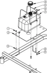
ONLY INCLUDED ON “CA” MODELS (CALIFORNIA COMPLIANT)
| Item # | Qty | Description | Part # |
| 1 | 4 | Screw – 10-24 X 3/4 Phil Truss Head ZP | 024203 |
| 2 | 2 | Bracket – Carbon Canister, ZT | 17127 |
| 3 | 4 | Nut – 10-24 Nylon Lock | 024900 |
| 4 | 1 | Carbon Canister – 2.50 Gallon, 3/16 Line | 18224 |
| 5 | 2 | Cable Tie – Carbon Canister | 18219 |
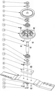
CENTER BLADE DRIVER DETAIL
| Item # | Qty. | Description | Part # |
| 1 | 4 | Nut – Serr Flange, 1/4-20 | NB524 |
| 2 | 2 | Bearing – Blade | B98 |
| 3 | 1 | Pulley – Blade, 5″ A | 20651 |
| 4 | 2 | Washer – Belleville .773ID X 1.50OD | AS155 |
| 5 | 3 | Washer – 3/4 ID X 1 1/4 OD | NB179 |
| 6 | 1 | Spacer – 3/4ID X 1 1/2 | 6065PM |
| 7 | 1 | Blade – G6 Gator, 20.5″ | 20186 |
| 8 | 1 | Nut – Jam 3/4-16 | NB175 |
| 9 | 1 | Plate – Blade Mount | 9008 |
| 10 | 2 | Nut – Lock, Two Way 3/8-24 | NB216 |
| 11 | 2 | Bolt – 3/8-24 X 1 1/4 | NB166 |
| 12 | 1 | Washer – Belleville .413IDX .945OD | NB607 |
| 13 | 1 | Bolt – HHC 3/8-24 X 1 | NB238N |
| 14 | 1 | Washer – Flat 3/4 ID X 1 3/4 OD | B98W |
| 15 | 1 | Housing – Cast Iron Blade Driver | 19924 |
| 16 | 4 | Bolt – Serr Flange, 1/4-20 X 1 | 13182 |
| 17 | 1 | Shaft – Blade, 6.563 | 20656 |
| 18 | 1 | Pulley – Blade, 5.5″ A/B | 21893 |
| Recommended Torque Specifications | |
| Part No. | Torque (ft-lbs) |
| NB175 | 90 |
| NB238N | 35 |
| NB524 | 20 |
| NB216 | 35 |
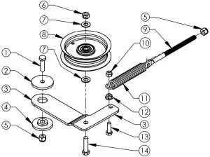
OUTER BLADE DRIVER DETAIL
| Item # | Qty. | Description | Part# |
| 1 | 4 | Nut – Serr Flange, 1/4-20 | NB524 |
| 2 | 2 | Bearing – Blade | B98 |
| 3 | 1 | Pulley – Blade, 5″ A | 20651 |
| 4 | 1 | Nut – Jam 3/4-16 | NB175 |
| 5 | 1 | Washer – Belleville .773ID X 1.50OD | AS155 |
| 6 | 3 | Washer – 3/4 ID X 1 1/4 OD | NB179 |
| 7 | 1 | Blade – G6 Gator, 20.5″ | 20186 |
| 8 | 1 | Plate – Blade Mount | 9008 |
| 9 | 2 | Nut – Lock, Two Way 3/8-24 | NB216 |
| 10 | 2 | Bolt – 3/8-24 X 1 1/4 | NB166 |
| 11 | 1 | Washer – Belleville .413IDX .945OD | NB607 |
| 12 | 1 | Bolt – HHC 3/8-24 X 1 | NB238N |
| 13 | 1 | Washer – Flat 3/4 ID X 1 3/4 OD | B98W |
| 14 | 1 | Housing – Cast Iron Blade Driver | 19924 |
| 15 | 1 | Shaft – Blade 5″ | 9077 |
| 16 | 4 | Bolt – Serr Flange, 1/4-20 X 1 | 13182 |
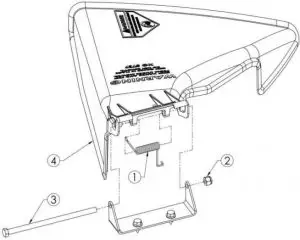
MOWER DECK DETAIL
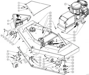
| ITEM # | QTY | PART NO | DESCRIPTION |
| 1 | 2 | 18391 | Cover – Belt, Black Composite |
| 2 | 8 | 18531 | Washer – Bent .25″ ID X 18GA |
| 3 | 8 | NB703 | Screw – MSC, 10-24 X 1 1/4 |
| 4 | 8 | 18532 | Nut – Clip, 10-24 |
| 5 | 1 | — | See Grass Chute & Spring Detail |
| 6 | 11 | NB596 | Bolt – Serr Flange 5/16-18 X 3/4 |
| 7 | 1 | 092104* | Bracket – Deflector |
| 8 | 2 | NB577 | Bolt -1/2-13 X 3 1/2 |
| 9 | 3 | 3511 | Wheel – Gauge |
| 10 | 4 | NB121 | Nut – Jam Lock 1/2-13 2-Way |
| 11 | 1 | 15780* | Bracket – Wheel Right |
| 12 | 19 | NB170 | Nut – Serr Flange 5/16-18 Z |
| 13 | 1 | 18383* | Bracket – Middle Roller |
| 14 | 1 | NB688 | Nut – Nyloc Jam, 1/2-13 ZY |
| 15 | 1 | NB132 | Bolt -1/2-13 X 4 HCC |
| 16 | 1 | NB281 | Nut – Nyloc 1/2-13 ZY |
| 17 | 1 | — | See Engage Lever Detail |
| 18 | 2 | T2PB | Bushing – Plastic |
| 19 | 1 | 18384* | Bracket – Deck Hanger |
| 20 | 1 | NB509 | Bolt – 1/2-13 X 2 HCC |
| 21 | 1 | 15779* | Bracket – Left Wheel |
| 22 | 11 | 26X249 | Screw – .312-18X.75 |
| 23 | 1 | NB707 | Bolt – Carriage 3/8-16X4 |
| 24 | 2 | AS001 | Roller – Anti-Scalp 3/8 ID |
| 25 | 1 | NB207 | Nut – Nyloc 3/8-16 |
| 26 | 1 | 21096* | Shield – Debris |
| 27 | 1 | 18382* | Weldment – Deck |
| 28 | 2 | NB106 | Bolt – 5/16-18 X 2 3/4 HCC |
| 29 | 2 | NB181 | Nut – Nyloc 5/16-18 |
| 30 | 1 | — | See Center Blade Driver Detail |
| 31 | 1 | — | See Motor Base Detail |
| 32 | 1 | — | See Safety Switch Bracket Detail |
| 33 | 1 | — | See Idler Detail |
| 34 | 2 | — | See Outer Blade Driver Detail |
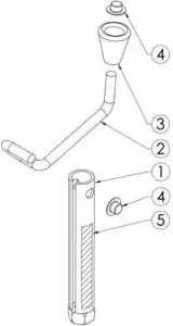
GRASS CHUTE & SPRING DETAIL
| ITEM # | QTY. | PART NO. | DESCRIPTION |
| 1 | 1 | 166X34 | Spring – Torsion |
| 2 | 1 | NB182 | Nut – Nyloc 3/8-16 zy |
| 3 | 1 | NB784 | Bolt – HCC 3/8-16 x 7 |
| 4 | 1 | 092100 | Chute – Discharge |
CASTER / WHEEL ASSEMBLY DETAIL
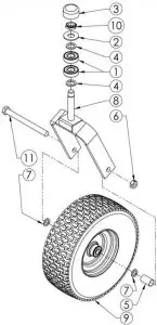
| ITEM # | QTY. | PART NO. | DESCRIPTION |
| 1 | 2 | B98 | Bearing |
| 2 | 1 | 17X195 | Washer – Flat |
| 3 | 1 | 094618 | Cap |
| 4 | 2 | NB195 | Washer – 13/16 ID X 1 1/4 OD X 1/8 |
| 5 | 1 | 663L | Spacer |
| 6 | 1 | NB595 | Nut – Locking Jam, 2 Way 5/8-11 |
| 7 | 2 | NB178 | Washer – 5/8 ID X 1 OD 10 GA |
| 8 | 1 | 665* | Weldment – Caster |
| 9 | 1 | F4157WK | Tire/Wheel – 5/8 Bearing 13x5x6 NHS, Blk |
| 10 | 1 | NB122 | Nut – Nyloc Jam 3/4-16 |
| 11 | 1 | NB624 | Bolt – 5/8″-16 X 7″ HCC ZY Grade 5 |
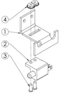
MOTOR BASE DETAIL
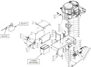
| PARTS NOT SHOWN | |
| 20899 | Harness – Wiring |
| BCSR | Cable – Battery (10″ Red) |
| BCLB | Cable – Batt ery (19 1/2″or 20″ Black) |
| KSK | Keys – For Key Switch (set of t wo) |
| BCBT | Boot – Rubber, Small, Battery Cable |
| ITEM # | QTY. | PART NO. | DESCRIPTION |
| 1 | 10 | 024206 | Screw – 12 X 1/2 Hex Self Tap |
| 2 | 1 | 17840* | Cover – Battery Top |
| 3 | 1 | 17616* | Cover – Battery Right |
| 4 | 2 | 26X263 | Screw – TCS 1/4-20 X 5/8 |
| 5 | 1 | 4226K | Knob – T, For Throttle Cable |
| 6 | 1 | 20916 | Cable – Throttle |
| 7 | 1 | 17614* | Cover – Battery Top Front |
| 8 | 1 | 9087 | Nut – Key Switch |
| 9 | 1 | 9088 | Washer – Lock, Key Switch |
| 10 | 1 | 685SP | Switch – Toggle, Single Pole |
| 11 | 6 | NB161 | Screw – HX Tek 1/4 X 3/4 ZP |
| 12 | 1 | 3623 | Switch – Key |
| 13 | 2 | NB180 | Nut – Nylock 1/4-20 |
| 14 | 1 | 17794* | Bracket – Battery Hold Down |
| 15 | 1 | 17615* | Cover – Battery Left |
| 16 | 2 | 17760 | Bolt-L |
| 17 | 3 | NB524 | Nut – Serr Flange, 1/4-20 Grade 5 |
| 18 | 1 | 14869 | Guide – Belt; T60 |
| 19 | 3 | NB275 | Washer – SAE Flat 5/16 |
| 20 | 3 | NB250 | Bolt – 1/4-20 X 3/4 GR5 |
| 21 | 1 | 16000 | Valve – Oil Drain |
| 22 | 1 | 18810 | Adapter – Oil Drain, Kawasaki |
| 23 | 1 | N/A | Engine (Reference Model Shown) |
| 24 | 1 | 1002004 | Solenoid – 3 Pole |
| 25 | 2 | NB114 | Bolt – TCS 1/4-20 X 1/2 |
| 26 | 1 | 20935 | Guide – Belt, FC |
| 27 | 4 | NB711 | Washer – Split Lock, 3/8 ZY, Medium |
| ITEM # | QTY. | PART NO. | DESCRIPTION |
| 28 | 4 | NB618 | Bolt – 3/8-16 X 1 1/4 GR5 ZY |
| 29 | 1 | NB210Z | Nut – 5/16-18 HNC |
| 30 | 2 | NB181 | Nut – Nyloc 5/16-18 |
| 31 | 1 | NB280 | Nut – 2 Way Lock 3/8-16 Wax Gr A |
| 32 | 1 | 6009* | Idler – Engage Weldment |
| 33 | 1 | B527 | Pulley – Idler, OD3.25″ ID3/8″ |
| 34 | 1 | NB272 | Washer – SAE Flat 3/8 |
| 35 | 1 | NB107 | Bolt – 3/8-16 X 1 1/2 HCC GR5 |
| 36 | 1 | 10636YZ | Bolt – Spade, 5/16-18 X12 |
| 37 | 1 | 20919 | Muffler – Kawasaki |
| 38 | 1 | 689L | Spacer – Long, Engine Pulley, 1.5″ |
| 39 | 1 | 9031 | Key Stock – 1/4 X 1 Undr Size |
| 40 | 1 | 688 | Pulley – Engine, 5.5″ |
| 41 | 1 | 689S | Spacer – Short, Engine Pulley, .687 |
| 42 | 1 | TR150W | Washer – .531IDX1 1/2ODX.062(Ht Trtd) |
| 43 | 2 | 699 | Washer – Belleville 7/16 X 1 1/4 |
| 44 | 1 | NB452N | Bolt – 7/16-20 X 1 HCF GR5 Nylock |
| 45 | 1 | NB182 | Nut – Nyloc 3/8-16 |
| 46 | 1 | 20904* | Motor Base – Weldment |
| 47 | 1 | — | See Saftey Switch Detail |
| 48 | 1 | NB172 | Nut – Kep 10-24 ZY |
| 49 | 1 | 21894 | Eyebolt – 10-24 X 1 3/8, w/ Nut |
| 50 | 1 | BRS6 | Spring |
| 51 | 1 | NB596 | Bolt – Serr Flange, 5/16-18 X 3/4 |
| 52 | 1 | 4422 | Spring – Idler Tension, Bent Leg |
| 53 | 1 | NB220 | Bolt – Shoulder 3/8-16X3/4 1/2X1-9/16 |
| 54 | 1 | 6736 | Tether – Safety, Coiled |
| Engage Lever Detail | Height Adjust Handle Detail | Safety Switch & Bracket Detail | |||||||||
| ITEM # | QTY. | PART # | DESCRIPTION | ITEM # | QTY. | PART # | DESCRIPTION | ITEM # | QTY. | PART # | DESCRIPTION |
| 1 | 1 | NB155 | Bolt – 1/2-13 X 5 HCC GR5 ZP | 1 | 1 | H7N1TK** | Tube – Height Adjust | 1 | 1 | 18390* | Mount – Switch Safety |
| 2 | 1 | 21929* | Lever – Engage | 2 | 1 | ES214** | Rod – Crank, For H7N | 2 | 1 | 3695 | Switch – Normally Closed |
| 3 | 2 | NB121 | Nut – 2 Way Lock 1/2-13 ZY | 3 | 1 | H7K** | Knob – Height Adjustment | 3 | 2 | NB197 | Screw – Phillips Truss 8-32 X 1/2 |
| 4 | 2 | NB555 | Washer – 1/2 | 4 | 2 | NB117** | Nut – Push, 5/16 | 4 | 2 | NB201 | Nut – Kep 8-32 |
| 5 | 1 | NB253 | Bolt – Serr Flng,5/16-18 X1 1/4 | 5 | 1 | OD41** | Decal – Ruler |
|
|||
| 6 | 1 | 2077 | Pivot – Handle Grip | **Parts Included in Service Part # H7N | |||||||
| 7 | 1 | NB170 | Nut – Serr Flng 5/16-18 | ||||||||
| 8 | 1 | 11158 | Nut – Jam, 2-Wy Lck, 5/16-18 | ||||||||
| 9 | 1 | 4578* | Pivot – Engage | ||||||||
| 10 | 1 | NB181 | Nut – Nyloc 5/16-18 | ||||||||
20946 Idler Detail
| ITEM # | QTY. | PART # | DESCRIPTION |
| 1 | 1 | NB618 | Bolt – 3/8-16 X 1 1/4 GR5 |
| 2 | 1 | 6040Z | Washer – Idler |
| 3 | 1 | 6054* | Idler – Bottom |
| 4 | 1 | 6037 | Bushing – Idler |
| 5 | 2 | NB182 | Nut – Nyloc 3/8-16 |
| 6 | 1 | NB280 | Nut – 2 Way Lock 3/8-16 Gr A |
| 7 | 1 | NB272 | Washer – SAE Flat 3/8 |
| 8 | 1 | 20183 | Pulley – Idler, 1″ X 4″ X 3/8″ ID |
| 9 | 1 | 21288 | Bolt – Spade, 3/8-16 X 6.5 |
| 10 | 1 | NB181 | Nut – Nyloc 5/16-18 |
| 11 | 1 | 21425 | Spring – Extension |
| 12 | 1 | NB170 | Nut – Serr Flange 5/16-18 |
| 13 | 1 | NB501 | Bolt – 5/16-18 X 1 GR5 |
| 14 | 1 | NB107 | Bolt – 3/8-16 X 1 1/2 GR5 |
Belt Configuration
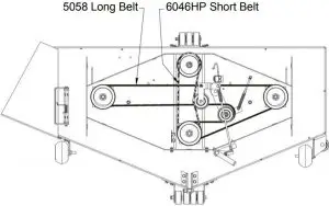
When ordering replacement part When ordering replacement part code: GT =Gray TK=Black
HOW TO ORDERREPAIR PARTS: 60” FAST FINISH TRAIL MOWER COMMERCIAL PRO
Each mower has its own model number. Each engine has its own model number. The model number for the mower will be found at the left rear of the unit on the belt cover skirt.
The model number for the engine will be found on the top of the blower fan housing.
All mower parts listed herein may be ordered directly from
Swisher or your nearest Swisher dealer.
All engine parts may be ordered from the nearest dealer of the engine supplied with your mower.
Color cannot be guaranteed on service parts.
WHEN ORDERING PARTS, PLEASE HAVE THE FOLLOWING INFORMATION AVAILABLE:
* PRODUCT – FC60 FAST FINISH TRAIL MOWER
* SERIAL NUMBER – _______________
* MODEL NUMBER – _______________
* ENGINE MODEL NUMBER – _______________
TYPE – _______________
* PART NUMBER
* PART DESCRIPTION
TELEPHONE – 1-800-222-8183
FAX – 1-660-747-8650
SWISHER ACQUISITION INC.
1602 CORPORATE DRIVE
WARRENSBURG, MO 64093
swisherinc.com
OWNER’S MANUAL
MODEL NO.
STARTING SERIAL #:
L115260001
20020
IMPORTANT
Read and follow all safety precautions and Instructiobefore operating this equipment.
 Model 20020 shown
ROAD BUSTER
GRAVEL GRADER
1602 CORPORATE DRIVE, WARRENSBURG, MISSOURI 64093
PHONE 800-222-8183 FAX 660-747-8650 EMAIL [email protected]
Manufacturing quality lawn care equipment since 1945
LIMITED WARRANTY
The manufacturer’s warranty to the original consumer purchaser is: This product is free from defects in materials and workmanship for the period’s shown below beginning from the date of purchase by the original consumer purchaser. We will repair or replace, at our discretion, parts found to be defective due to materials or workmanship. This warranty is subject to the following limitations and exclusions:
| Materials and Workmanship | 3 Years |
| Commercial Use | The warranty period for this product when used for commercial or rental is limited to 1 year from the date of original purchase. |
| Limitation | This warranty applies only to products that have been properly assembled, adjusted, and operated in accordance with the instructions contained within this manual. This warranty does not apply to any product of Swisher that has been subject to alteration, misuse, abuse, improper assembly or installation, shipping damage or to normal wear of the product. |
| Exclusions | Excluded from this warranty are normal wear items, normal or routine adjustments, and normal or routine maintenance. |
In the event you have a claim under this warranty, you must return the product to an authorized service dealer. All transportation charges, damage, or loss incurred during transportation of parts submitted for replacement or repair under this warranty shall be borne by the purchaser. Should you have any questions concerning this warranty, please contact us toll-free at 1-800-222-8183. The model number, serial number, date of purchase, and the name of the authorized Swisher dealer from whom you purchased the splitter will be needed before any warranty claim can be processed.
HIS WARRANTY DOES NOT APPLY TO ANY INCIDENTAL OR CONSEQUENTIAL DAMAGES AND ANY IMPLIED WARRANTIES ARE LIMITED TO THE SAME TIME PERIODS STATED HEREIN FOR ALL EXPRESSED WARRANTIES. Some states do not allow the limitation of consequential damages or limitations on how long an implied warranty may last, so the above limitations or exclusions may not apply to you. This warranty gives you specific legal rights and you may have other rights, which vary from state to state. This is a limited warranty as defined by the Magnuson-Moss Act of 1975.
SAFETY PRECAUTIONS
 This Safety Alert Symbol indicates important messages in this manual. When you see this symbol, carefully read the message that follows and be alert to the possibility of personal injury.
Read this manual completely. This machine can amputate hands, feet, and throw objects. Failure to observe the following safety instructions could result in serious injury or death.
- Read and understand the manual. Learn to operate this equipment in a safe manner. Familiarize yourself with all of the controls in a safe environment before starting to work with this machine.
- DO NOT under any circumstances alter this Grader. This equipment was designed and engineered in accordance with operating instructions. Altering this equipment, or using this equipment in such a way as to circumvent its design capabilities and capacities, could result in serious injury or fatality and
WILL VOID THE WARRANTY. - Allow ONLY responsible adults who have read this manual to operate this machine. NEVER allow children to operate this machine.
- NEVER operate or allow someone to operate this equipment while under the influence of alcohol, drugs or medication. Being coherent is essential for safety.
- NEVER use grader for any other purpose than grading non-public roadways/driveways. Any other use can result in injury. Your grader is a precision piece of power equipment, not a toy. Therefore, exercise extreme caution at all times.
- ALWAYS wear protective gear such as safety goggles, steel-toed shoes, and a helmet if on an ATV/UTV.
- BEFORE towing, be certain that the grader is securely attached to the towing vehicle and that the support leg is secured in the towing positions.
- NEVER allow persons to ride on the grader. DO NOT carry any cargo on your grader other than weight that is secured on the mainframe weight tray provided.
- ALWAYS watch for the traffic of any kind when near or around roadways.
- ALWAYS shut the towing vehicle off and apply the emergency brake if applicable, before getting off to the service grader.
- ALWAYS use grader only when sufficient lighting/daylight is present.
- NEVER operate the grader on slopes greater than 15°.
- NEVER attempt to work on the electric motor or electrical devices yourself. Contact customer service
and they will find a qualified service center. - ALWAYS check working parts on grader before each use for worn or broken parts that would need
replaced. - ONLY use manufacturer-recommended replacement parts.
TOWING SAFETY
- Be sure the support jack stand is in the travel position and the coupling is secure. This must also be retracted so as not to interfere while towing. Retract the jackstand by removing the pin, pivoting up, and replacing the pin.
- Never exceed 15 MPH while towing your grader. Be extra cautious when traveling over rough terrain.
- Always be careful while backing your grader. You could jackknife your grader if not careful.
- See tire and wheel specifications for PSI while towing.
- Be aware of the extra length of grader while turning, parking, crossing intersections, and in all driving situations.

OPERATION INSTRUCTIONS
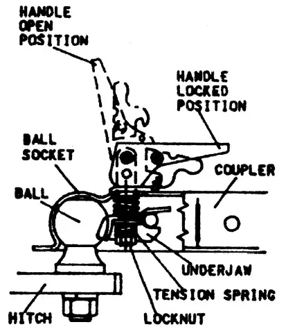
POSI-LOCK COUPLER
ADJUST COUPLER LOCKING PRESSURE ON BALL BEFORE USE. PLACE HANDLE IN LOCKED POSITION WITH BALL IN COUPLER. TIGHTEN LOCKNUT AGAINST TENSION SPRING SO THAT COUPLER IS NOT LOOSE ON BALL. CORRECT ADJUSTMENT WILL ALLOW THE HANDLE TO BE RELEASED WITH MODERATE PRESSURE APPLIED TO THE HANDLE.
TO OPEN, PULL UP ON THE COUPLER HANDLE AND ROTATE FORWARD. PLACE COUPLER ON BALL WHEN BALL IS COMPLETELY NESTED IN BALL SOCKET, ROTATE COUPLER HANDLE BACKWARD UNTIL HANDLE IS IN LOCKED POSITION.
AFTER TOWING, CHECK THE COUPLER FOR TIGHTNESS ON THE BALL. ALWAYS CHECK TIGHTNESS BEFORE TOWING. BE SURE THE COUPLER HANDLE IS IN A LOCKED POSITION.
WARNING:
NEVER EXCEED WEIGHT CAPACITY. ALWAYS USE THE CORRECT BALL SIZE, MAKING SURE THE BALL S COMPLETELY INSERTED INTO THE COUPLER. LOCK COUPLER HANDLE SECURELY BEFORE TOWING. ALWAYS CHECK FOR DAMAGES AND REPLACE IF DAMAGED. AVOID SHARP TURNS AND STEEP VERTICAL ANGLES WHEN TOWING.
MAINTENANCE & STORAGE
When storing the grader always lowers the grader to which the scarifiers contact the ground and the actuator is relieved of carrying any load. It is not recommended to ever leave the grader stored with the actuator holding the weight of the unit.
It is recommended to use the jack stand provided to raise and lower the unit when connecting and disconnecting from vehicles. DO NOT try and lift the weight of the grader by yourself when uncoupling, it may cause injury.
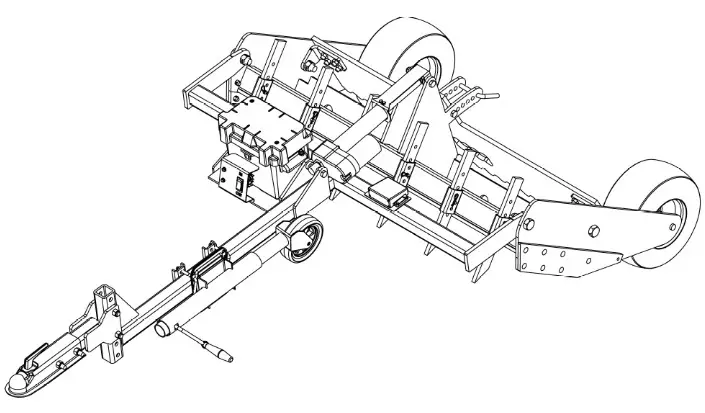
INTENDED USE / RECOMMENDED VEHICLES
The grader is intended to refinish non-public driveways or roadways consisting of primary gravel and or rock. Be aware of your surroundings and what is beneath the ground you intend to use the grader on. ALWAYS avoid large rocks, embedded obstacles, and buried utilities such as gas, electric, or phone lines.
A minimum of a 500 cc ATV/UTV or a 20 HP /500 lb. garden tractor is required to pull the grader and a Four-wheel or all-wheel drive is always recommended when available on the vehicle to gain maximum traction to ensure the best performance.
Understand that the amount of ground engagement with the scarifiers depends strongly on the type of vehicle you are using and the media makeup that you are refinishing. The looser the media and the more traction from the vehicle allow more ground engagement and the lighter the vehicle and more hard-packed the media allows less engagement.
It is recommended to start with minimum engagement (1/4”-1/2”) when beginning to refinish an area, and as the ground loosens increase the depth of engagement on scarifiers.
The grader design allows the operator to add weight to the unit if necessary to break up the ground when pulled with an adequate vehicle. The weight area is located in the mainframe section on the unit on either side of the actuator mount. Any additional weight should not exceed 100 lbs and should always be secured within the weight area by any means possible.
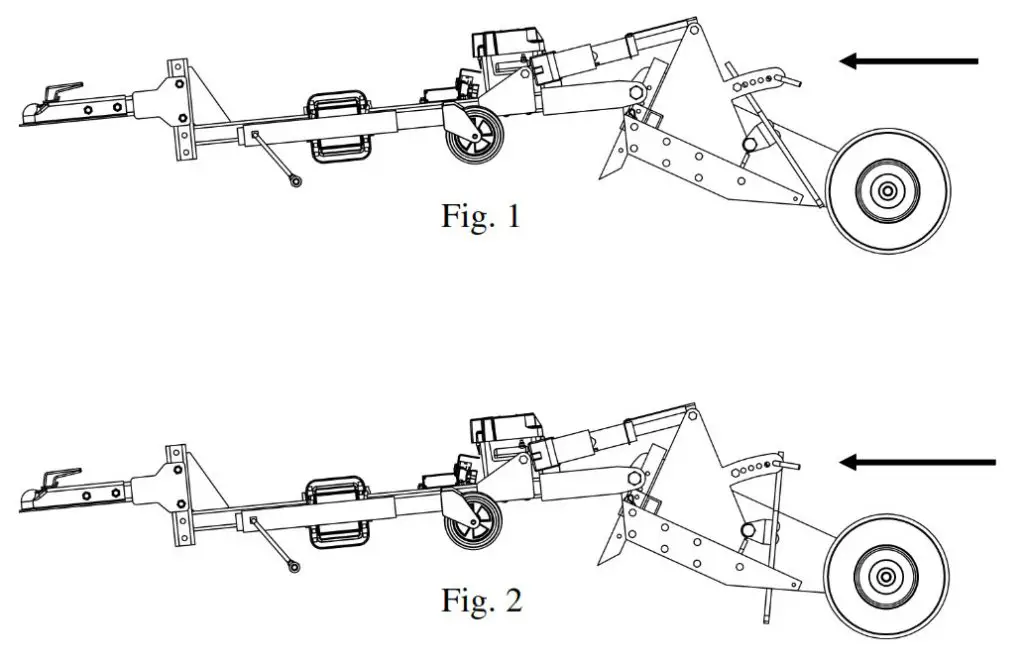
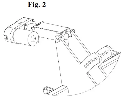
 The rear blade on the grader can be used in several positions depending on the work you are doing. In fig. 1 the blade is free-floating and only restrained by the pin in the last pin position. This allows the blade to swing freely and the weight of the blade helps level and smooth loose media. In fig 2 the blade is pinned in the upright position and the grader can act as a scrapping blade when scarifiers are raised up away from media.
TRANSMITTER AND RECEIVER
The grader comes equipped with a remote control to raise and lower the unit by an electric actuator. The remote has two buttons, one to extend and one to retract the actuator. Follow the directions below to activate the remote once the battery is installed.
- Once the receiver is plugged into a power source, with the remote in hand hold down the button on the receiver box until a GREEN LED light comes on solid.
- Once the GREEN LED is solid hold down one of the buttons on the remote for approximately one second and verify the GREEN LED light flashes momentarily when the button is pressed.
- Repeat this process but with the opposite button on the remote
- Once both signals have been sent to the receiver the LED light on the receiver should turn solid RED. This means your transmitter and receiver are now paired.
- Press the IN and OUT buttons as needed.
To turn off the wireless system press the button on the receiver box once and ensure there is no longer a LED light on.

LED Indicator Light
Steady RED – The system is active and ready to use.
Flashing RED during use – The battery or power source is low.
RED light is off – The wireless remote control is turned off, or not active.
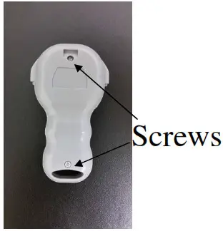
Replacing batteries
If the indicator light on the handheld remote flashes during use, the batteries are low and should be replaced.
- Remove the two screws from the handheld remote located on the back of the remote.
- Separate the top and bottom sections of the remote using a flat head screwdriver or similar device.
- Remove the old batteries and dispose of them in accordance with local environmental regulations.
- Insert (2) new A23 style alkaline batteries as shown with the positive terminals facing the switches. Do not mix old and new batteries.
- Join the top and bottom sections making sure they snap together and the rubber seal remains intact.
- Secure with the two screws.
ASSEMBLY
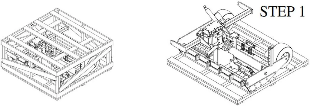
This grader has been mostly assembled at the factory. Refer to uncrating and assembly instructions below to complete the final assembly steps. Refer to the drawings and part lists should it become necessary to disassemble the unit for repair or replacement of parts.
Inspect all components for damage. If you believe you have a damaged part please contact customer service immediately at 1-800-222-8183.
TOOLS REQUIRED: (2) ¾” WRENCH OR SOCKET, (2) 1 ¼” WRENCHES/SOCKETS OR LARGE CRESCENT WRENCHES HAMMER, CROWBAR/PRYBAR, WIRE CUTTERS, GLOVES, AND PROTECTIVE EYEWEAR RECOMMENDED
WARNING: Exercise extreme caution, as parts are very heavy. Sufficient persons or mechanical handling equipment should be used.
Step 1: Carefully remove the top, sides, and ends of the crate with a hammer and pry bar.
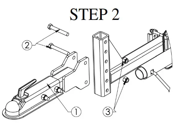
 Step 2: Remove the ball coupler assembly #1 from within the frame assembly and install it onto the tongue assembly with the NB577 (bolts) #2 and NB281 (nuts) #3 provided.
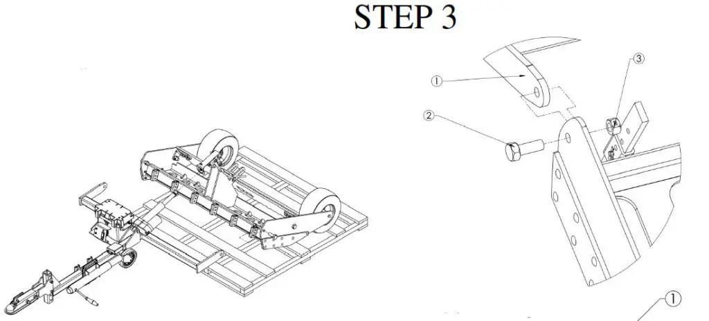
Step 3: Remove main tongue assembly from crate and bolt, both frames end #1 to the inside of mainframe rail sides using (2) 11431 bolts #2 and (2) 13997 nuts #3 provided. Tighten hardware snug but do not lock completely, allow frame assemblies to hinge.
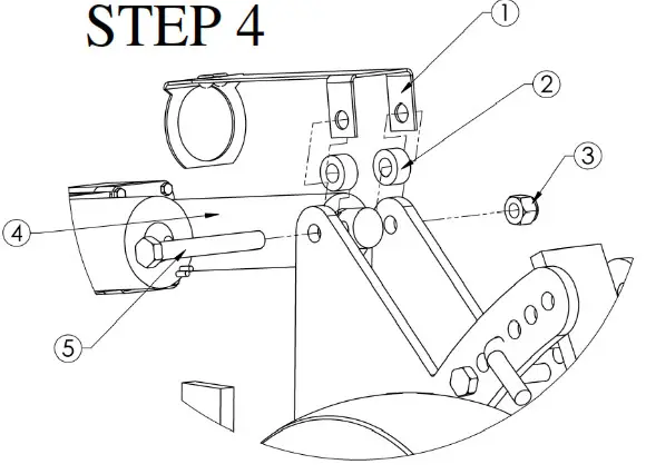
Step 4: Once the two mainframe assemblies are fastened, install the 20008TK height indicator bracket #1 over actuator #4 and slide towards the front of nit. While holding the actuator up run NB132 bolt #5 through fram20008TK #1, 19942TK #2, actuator, then through the second spacer and the opposite side of the bracket. Capture the bolt with the NB281 nu#3 provided.
SHOWN BELOW IN FIG. 2 IS THE PROPER ASSEMBLY OF THE HEIGHT INDICATOR AND ACTUATOR.
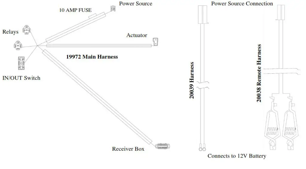
Supplying Power to the Grader
The grader is supplied with two power leads. The remote power lead (20038) is designed to be attached to your ATV/UTV or other vehicle’s 12V battery. The onboard power lead (20039) is designed to hook up to a battery installed directly on the grader. Both power leads plug directly into the grader wiring harness but the only one can be used at a time. The 20039 harness requires (2) NB524 nuts and (2) NB690 bolts to fasten to battery posts. These are located in the parts bag.
Caution: Always be sure to install a RED wire of lead to the Positive side of the battery and a BLACK wire of lead to the negative side of the battery. ALWAYS disconnect the negative (black) lead from the battery first and install the negative (black) last when reconnecting to the battery. Caution: Always be sure to secure the remote lead to the tongue of the grader and vehicle so as not to drag on the ground or become tangled in the unit.
*Below is a visual of all harnesses and where the connections attach.
NOTE: Grader does not come supplied with a battery but has the option of installing an onboard battery. The unit is designed to use a 12 V U1 or U1 deep cycle battery.
Any other style of the battery may not mount on the unit correctly or allow the unit to function properly.
Maintaining Battery: It is very important to recharge a battery after each use or if completely drained, and also recommended to install a battery tender (charger) on to the battery when not in use. IT IS NOT recommended to charge a battery at more than a 10 amp rate for extended periods of time.
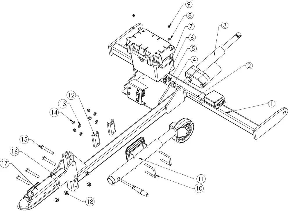
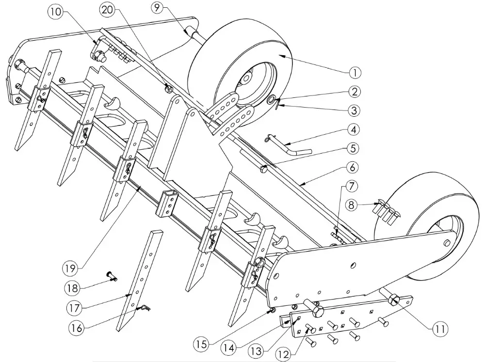
PARTS BREAKDOWN
| ITEM NO. | PART NUMBER | DESCRIPTION | QTY. |
| 1 | 19946TK | Weldment – Main Tongue, Grader; Txt BIk | 1 |
| 2 | NB577 | Bolt – 1/2-13 X3 1/2 GR5 ZY | 1 |
| 3 | 19957 | Actuator – 12VDC, 20:1, ACME 6′,1500# | 1 |
| 4 | 19942TK | Spacer – .5151D X l’OD X .500N, Txt BIk | 2 |
| 5 | NB100 | Bolt – Carriage, 1/4-20 X 6 GR5 | 2 |
| 6 | NB281 | Nut – Nyloc 1/2-13 ZY | 1 |
| 7 | 19974 | Battery – Box, Grader | 1 |
| 8 | NB274 | Washer – SAE Flat 1/4 ZY | 2 |
| 9 | NB180 | Nut – Nyloc 1/4-20 | 2 |
| 10 | 12447 | Ubolt – SQ , 3/8-16X2.437 X 3 Lg GR 5 ZY | 2 |
| 11 | 19179 | Jackstand | 1 |
| 12 | 19477TK | Plate – Support, Kickstand Txt BIk | 2 |
| 13 | NB272 | Washer – SAE Flat 3/8 ZY Carbon Steel | 4 |
| 14 | NB182 | Nut – Nyloc 3/8-16 ZY | 4 |
| 15 | NB577 | Bott- 1/2-13 X3 1/2 GR5 ZY | 4 |
| 16 | 19958TK | Weldment – Hitch, Grader; Txt BIk | 1 |
| 17 | 7365 | Coupler – 2′ Ball | 1 |
| 18 | NB281 | Nut – Nyloc 1/2-13 ZY | 4 |
| 19 | 19962TK | Plate – Hitch, Latch; Txt BIk | 2 |
LATCH PIN OPTION
(Latch pin plates included in parts bag)
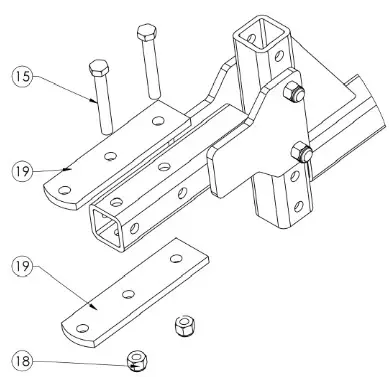
| ITEM NO. | PART NUMBER | DESCRIPTION | QTY. |
| 1 | 19971 | Tire -13 X 650-6 3/4 ID Smooth | 2 |
| 2 | NB195 | Washer -13/16 X 1 1/4 X 1/8 ZY; Mild | 2 |
| 3 | NB126 | Pin – Cotter, 1/8 X 1, Crbn St! Ext Pricing | 2 |
| 4 | 15177 | Bent Pin – W/ Hair Pin 1/20D X 3.5, ZP | 1 |
| 5 | NB132 | Bolt -1/2-13 X 4 HCC GR5 ZY | 1 |
| 6 | 19944TK | Plate – Rake, Grader, Txt BIk | 1 |
| 7 | NB121 | Nut -Jam Lock, 1/2-13 2-Way Gr A | 8 |
| 8 | 20057 | Bolt – Carriage, 1/2-13 X 1 1/2 GR5 ZY | 8 |
| 9 | 19961TK | Spacer – .750 ID X 1 OD X 1.250, Txt BIk | 2 |
| 10 | 19945TK | Bracket – Rake Hinge, Grader; Txt Blk | 2 |
| 11 | 11431 | Bolt – 3/4-10 X 2 GR8 ZY | 4 |
| 12 | 10501 | Bolt – Carriage 3/8-16 X 1 1/4 GR5 ZY | 14 |
| 13 | 19941TK | Plate – Outer Skid, Grader, Txt Bik | 2 |
| 14 | 19940TK | Plate – Inner Skid, Grader, Txt Blk | 2 |
| 15 | NB280 | Nut – 2 Way Lock 3/8-16 ZY & Wax Gr A | 14 |
| 16 | NB127 | Pin – Hair, # 39 (A155H)ZY Std | 6 |
| 17 | 19943TK | Scarifier – 4140 Rc28-32,Txt BIk | 6 |
| 18 | 20051 | Pin – Clevis, Std 3/8 X 1 1/4 ZY | 6 |
| 19 | 19929TK | Weldment – Main Frame, Txt BIk | 1 |
| 20 | NB281 | Nut – Nyloc 1/2-13 ZY | 1 |
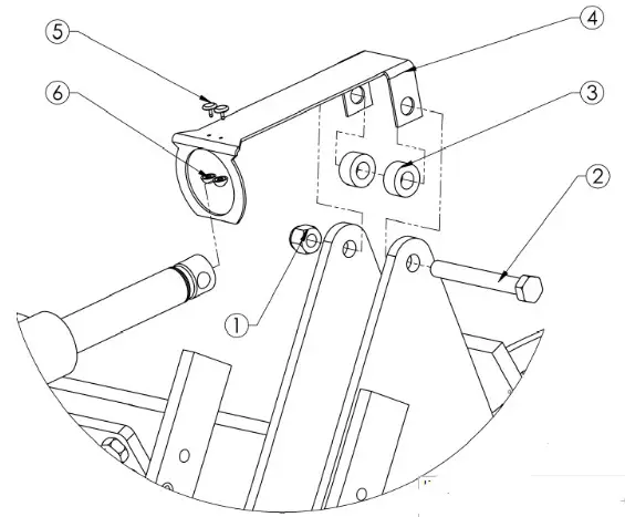
HEIGHT INDICATOR
| ITEM NO. | PART NUMBER | DESCRIPTION | QTY. |
| 1 | NB281 | Nut – Nyloc 1/2-13 ZY | 1 |
| 2 | NB577 | Bolt- 1/2-13 X3 1/2 GR5 ZY | 1 |
| 3 | 19942TK | Spacer – .5151 D X l’OD X .500′, Txt Bik | 2 |
| 4 | 20008TK | Bracket – Height indicator Txt BIk | 1 |
| 5 | 19857 | Button – Plastic, Bottom | 2 |
| 6 | 19858 | Button – Plastic, Top | 2 |
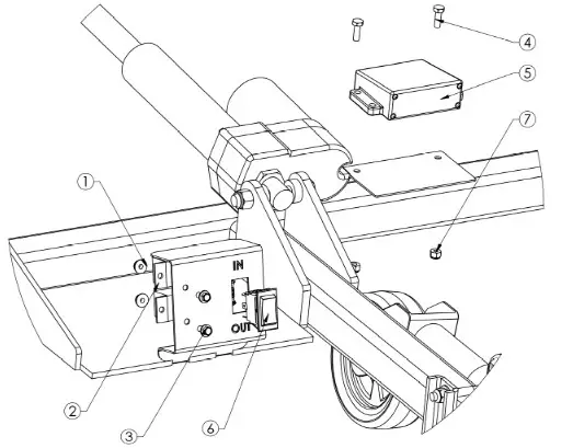
ELECTRICAL CONTROLS
| ITEM NO. | PART NUMBER | DESCRIPTION | QTY. |
| 1 | NB524 | Nut -Serr Flange, 1 /4-20 Grade 5 ZY | 2 |
| 2 | 15749 | Electrical – 12V 30 AMP Relay | 2 |
| 3 | NB690 | Bolt – Serr Flange, 1/4-20 X 3/4 GR5 ZY | 2 |
| 4 | NB250 | Bolt – 1/4-20 X 3/4 GR5 ZY | 2 |
| 5 | 19970 | Remote – Wireless, Grader | 1 |
| 6 | 19978 | Switch – DPDT, 30A, On-Off-On MOM | 1 |
| 7 | NB180 | Nut – Nyloc 1/4-20 | 2 |
SAFETY DECALS
Replace decals immediately if damaged.
 The operation of any grader can produce foreign objects to be thrown into the air, resulting in severe eye damage. Always wear certified safety glasses or wide-vision safety goggles over spectacles before and while operating such a machine.

MAINTENANCE LOG
| Date of Service | Service Performed | Notes |
SPECIFICATIONS
Dimensions
| Length | 95″ |
| Width | 50″ |
| Weight | 380lbs |
| Shipping Dim. | 51.5″ X 51.5″ X 24″ |
| Shipping Weight | 460lbs |
Working Dimensions
| Working Width | 50″ | |
| Max. Teeth Ground Clearance | 10″ | |
| Grading Depth Range | 1-10″ | 2″ max. ground engagement recommended with ATV/UTV |
| Total Scarifier Adjustment | 9″ |
Towing
| Recommended Towing Vehicle | Minimum 500cc ATV/UTV 4X4 Desired |
| Hitch Style | 2″ Ball Coupler and Hitch Pin both Standard |
Material
| Frame | Welded 3/8″ Steel & Tube |
| Scarifiers | Hardened 1/2″ Steel |
| Hardware | Minimum Grade 5 |
Miscellaneous
| Actuator | 1500 # Industrial Remote Controlled Linear |
| Tires/Wheels | 13 X 650-6 3/4 ID Smooth |
| Power Source | 12V U1 Deep cycle battery recommended |

SWISHER HISTORY
Back before electricity came to rural Missouri Max Swisher was producing lawnmowers from his mother’s chicken house. Max never liked to mow the grass. He installed a gearbox on his family’s lawnmower creating a self-propelled unit. By tying one end of a rope to the mower and the other end to a tree in the center of the yard the mower circled the tree, shortening the rope and guiding the mower in concentric circles. Max enjoyed relaxing under a shade tree while his invention did all the work.Max had designed his first self-propelled rotary lawn mower to do his dirty work for him.Neighbors noticed his new invention and began asking him to make more. Today, 60 years later, Swisher is still producing innovative lawn and garden and ATV/UTV equipment designed to give us all more “relaxing in the shade” time.Swisher products have been featured nationally on television programs such as Regis and Kathie Lee and seen in publications like ATV Magazine, Country Journal, Popular Mechanics Magazine and others. In January 2000 Popular Mechanics Magazine named Max’s zero-turning radius riding mower one of the 20 century’s top household inventions.Swisher offers value and function in its products to meet your grounds maintenance needs.CELEBRATING OVER 70 YEARS OF INNOVATION
SINCE 1945GRAVEL GRADER ROAD BUSTERHOW TO ORDER REPAIR PARTS:Each Grader has its own serial number.
All Grader parts listed herein may be ordered directly from Swisher, your nearest Swisher dealer, or from our website.WHEN ORDERING PARTS, PLEASE HAVE THE
FOLLOWING INFORMATION IS AVAILABLE:
* PRODUCT – SWISHER GRADER
* SERIAL NUMBER –
* MODEL NUMBER –
* ENGINE MODEL NUMBER –
* TYPE –
* PART NUMBER
* PART DESCRIPTION![]() www.swisherinc.com
www.swisherinc.com
TELEPHONE – 1-800-222-8183
FAX – 1-660-747-8650
SWISHER
1602 CORPORATE DRIVE
WARRENSBURG, MO 64093