

thermoflow Electric Mini Tankless Water Heater
Congratulations and thank you for choosing our electric tankless water heater. The instruction contain important information about commis-sioning, switching the device on and maintenance. To ensure your safety and that of others we recommend you read through this safety manual carefully. Please refer to the back of the manual for details about the warranty. Keep this manual for future reference.
If you lose the maunal, contact your local distributor or manufacturer. When you call, please tell us the model number and the serial number of your unit written on the rating plate of the water heater.
Use of the manual
This appliance can be used by children aged from 8 years and above and persons with reduced physical, sensory or mental capabilities if they are supervised during use of the appliance and understand the hazards involved.
This is not a toy. Children shall not play with this appliance.
Standards and regulations
The installation (plumbing and electrical work), commissioning and maintenance of this appliance should only be undertaken by person-nel with electrical qualifications and in accordance with the relevant standards and codes and this manual.
Correct and reliable operation of this unit will only be ensured if the original accessories and spare parts are used.
The following should also be observed:
the appliance name plate;
the technical specifications.
Mounting instructions
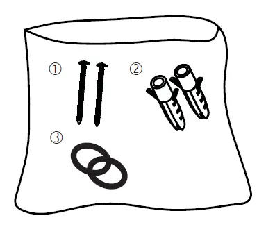
Contents
Water Connection
OPTION A – Act as primary heater, connect the inlet with cold water directly, and connect the outlet with mix tap.
OPTION B – Act as booster heater, connect the inlet with the outlet of storage tank, and connect the outlet with mix tap.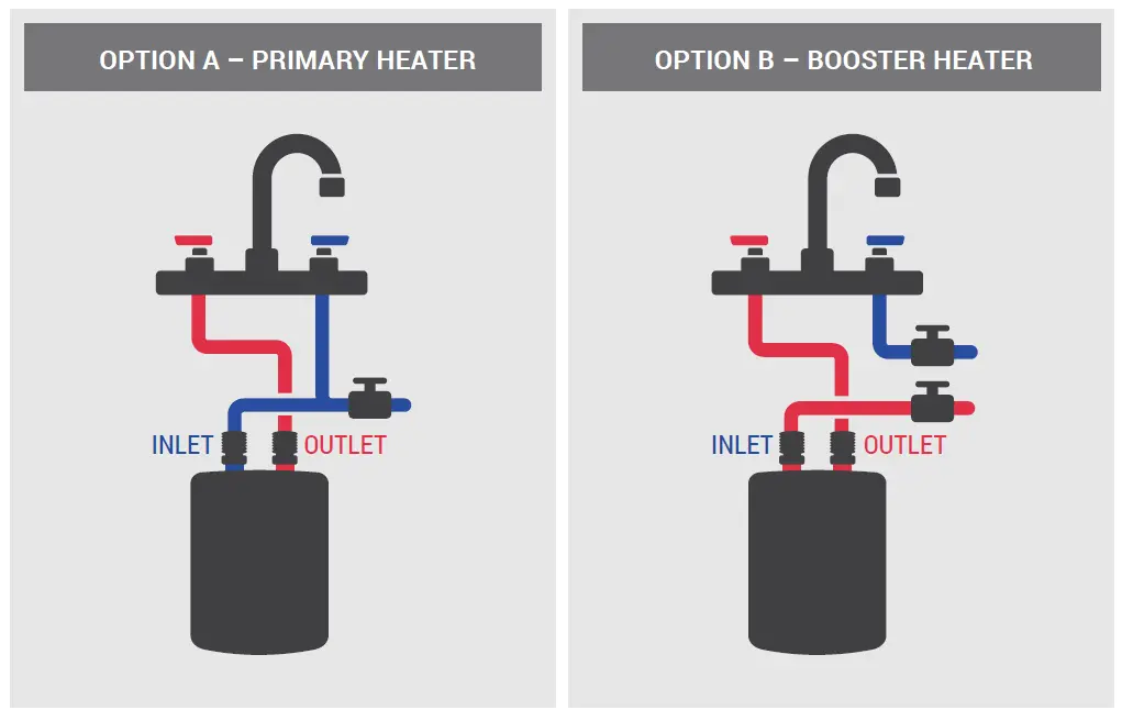
Unpacking
Check if the device has been damaged in any way.
Environment
To prevent damage during transport this unit is shipped in sturdy packing. Please recycle the packaging where possible.
Disposal of the appliance
Old appliances must not be disposed of in your household waste!Please bring old appliances to the appropriate recycling center nearest to you.
Tools
You will require the following tools for installation:
- Phillips-head screwdriver
- Open-ended wrenches
- Teflon tape
- Drill
- Stone or concrete drilling bits
- Pencil
- Adhesive tape
- Wire strippers
Model ThermoflowTM Elex 3.5/4.5/5.5 do not have plug and need to be connected with 220-240V supply directly.
If the electrical installation does not meet these requirements then it will need to be modified. This should be done by a qualitied electrician in accordance with the relevant regulations (IEC, NEC, etc.)
Preparing for installation
The water and electrical supply need to be available at the place where the device is to be supplied. If the electricity cable is buried in the wall then use the supplied spacers. If the electrical cable is fixed to the wall then the device can also be fixed straight to the wall.
Frost
If there is the risk of frost in a room, the device should not be installed in this room. If despite this advice, the device installed in a room where there is a risk of frost, the device should be drained of water before the risk arises.
Connection to the water supply
Blue = cold water entry side from pipe or tank (for filling)
Red = hot water exit side to tap (hot water demand)
The ThermoflowTM Elex 3.5/4.5/5.5 devices are designed for use normal pressure systems.
The water supply pipe and water discharge pipe are marked (red for hot water, blue for cold water).
Connection to the electricity supply
The device must be filled with water (see above). Only then may the appli-ance be connected to the electricity supply.
Connection of the device to the power supply network must take place in accordance with the NEC, IEC and as specified by local laws and regula-tions.
Avoid danger from damaged power supply cables. In the event of a damaged power supply cable, the unit should be unplugged and the cable replaced by a licenced electrician immediately.
Ensure that the addition of this boiler will not overload the fuse protection in your electrical panel.
Internal modifications to the product may cause problems if this work is not carried out by authorized and qualified technical persons. The warranty only applies if the product has not been modified in any way, i.e. subject to it being in unchanged condition.
In order to avoid creating an unsafe situation by inappropriate resetting of the maximum temperature safety device, this unit may not be powered via an external switching device (a time switch for example) or connected to a circuit, which is regularly switched on and off.
Drawing – Thermoflow Elex 3.5/4.5/5.5 TM
Installation as undersink/oversink cable model
- Switch off the power supply, then prepare the 220-240V power cord without plug, make sure the length no less than 12”.
- Mount the bracket on the wall and fix use two screws in the accessory bag.
- Disassemble the cover for the internal power cord connection.
- For the undersink installation, the two outlets are upper direction, the left outlet is the water inlet (cold / blue), right outlet is the water outlet (hot / red); For the oversink installation, the two outlets are lower direction, the left outlet is the water outlet (hot / red), right outlet is the water inlet (cold / blue). Select the installation you need and cross the power cord through the hole on the backboard, then push the water heater toward the bracket until listening “Click”.
- Connect the power cable to the internal terminal block, for the under-sink installation, terminal is GND-L2-L1 respectively from left to right, for the undersink installation, connector is L1-L2-GND respectively from left to right, then fix the power cable.
- Prepare water connections, assemble the cover, then switch on the power supply.
Technical specifications
| ThermoflowTM model | Elex 3.5 | Elex 4.5 | Elex 5.5 |
| Nominal voltage | 220-240V, 60Hz | 220-240V, 60Hz | 220-240V, 60Hz |
| Nominal power rating | 3.5 kW | 4.5 kW | 5.5 kW |
| Nominal current | 15 – 16 A | 19 – 21 A | 23 – 25 A |
| Circuit Breaker | 2-POLE 20A | 2-POLE 25A | 2-POLE 30A |
| Power plug included | Yes | No | No |
| Flow rate (∆t=45°F) | 0.5 GPM | 0.7 GPM | 0.8 GPM |
| Cable size | 14 AWG | 12 AWG | 12 AWG |
| Heating system | Bare elements | Bare elements | Bare elements |
| Min. water resistance at 59°F | ≥3300 Ω•inch | ≥3300 Ω•inch | ≥3300 Ω•inch |
| Switch on flow rate | 0.48 GPM | 0.53 GPM | 0.53 GPM |
| Non-usage consumption | <0.1 Wh/h | <0.1 Wh/h | <0.1 Wh/h |
| Protection class | I | I | I |
| Type of protection | IP 24 | IP 24 | IP 24 |
| Dimensions | 7⅝ x 5⅜ x 2⅝” | 7⅝ x 5⅜ x 2⅝” | 7⅝ x 5⅜ x 2⅝” |
| Unit weight | 1.8 lb | 1.8 lb | 1.8 lb |
| Water connections | 1/2” NPT | 1/2’’ NPT | 1/2” NPT |
| Max. pressure water mains | 90 PSI | 90 PSI | 90 PSI |
| Switch on flow pressure | 7.3 PSI | 7.3 PSI | 7.3 PSI |
Temperature Rise vs. Flow Rate at 240V
Note: Temperature rise = Hot Water Temp. – Cold Water Temp.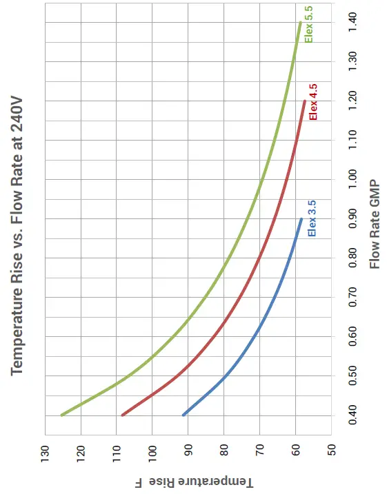
The device must be filled with water before connection to the electrical supply!
Important! Purging Air Out
Before switching “ON” the power at the main circuit breaker panel, make sure that the hot water circuit is free of air pockets or else premature failure of the element will occur.
This unit is equipped with a 2-stage power heating element. Therefore the outlet hot water temperature may vary in connection with inlet water temperature and flow rate. To get the desired temperature, adjust the hot water flow rate or add cold water at your mixer. Make sure the pressure of your water supply system supersedes 7.3 PSI.
This device does not require any maintenance by the user. Repairs should always be carried out by a licensed contrac- tor.
If faulty, never try to repair the device yourself. Please contact the nearest service specialist for help.
Care
The housing of the device can simply be cleaned with a damp cloth. Do not use harsh chemicals or abrasives!
Prolonged shutdown
Do not use heated water as drinking water.
After prolonged shutdown of the device for example after vacation, the device should be fully heated up to the maximum temperature (tap at minimum flow) before reusing. Pipes should be flushed for one minute. Check the filter which is incorporated in the cold water inlet of the device (blue) regularly and keep it free from debris and dirt. This can be accessed by separating the device from the tap. Make sure you have switched off the main power supply and the main water supply.
Trouble shooting
Symptom: No heat, indicator light off
| Cause | Remedy |
| Electric supply is off | Turn on the main circuit breaker. |
| No or low water flow | Ensure that the minimum water pressure (7.3 PSI) to switch on the device is met. Also check that the inlet filter screen is clear from any debris. |
| Water connections are reversed | Cold water inlet = blue; Hot water outlet = red. |
| Element burned out | Call local dealer for maintenance |
Prolonged shutdown
| Cause | Remedy |
| Water flow too high | Reduce the water flow. |
| Incorrect power supply | Make sure that the device is connected to the voltage supply specified on the rating label on the front cover of the device and no other. |
| Element burned out | Call local dealer for maintenance |
Warranty conditions
Warranty
The rights under this manufacturer’s warranty shall apply in addition to the buyer’s statutory rights. This warranty shall in no way restrict the buyer’s statutory rights.
Entitlement
The claiming of rights under this warranty shall be subject to the submis-sion of the respective proof of purchase.
Content
We guarantee as the manufacturer that this product is free of material and manufacturing errors. Material and manufacturing errors arising during the warranty period shall justify the rights under the warranty. This warranty shall not cover errors due to improper installation or incorrect usage, incorrect operating conditions, or improper maintenance or repair work.
Normal wear and tear such as lime scaling shall also be excluded under this warranty. The warranty will not be valid if the problem is caused by extreme values of drinking water (pH value not between 7 and 9.5 and/or Cl above 150 mg/l and/or Fe above 0.2mg/l).
Duration
The warranty shall be valid for 24 months. The warranty period shall commence on the day on which the product is purchased. Warranty services provided shall neither prolong the warranty period nor initiate a new warranty period.
Claims
The defective product should be sent together with the proof of purchase to the place of purchase.
We shall not be liable for transport damage. The product shall be repaired or replaced at the discretion of us. The functioning product shall then be sent to the buyer. We shall acquire ownership of replaced parts or products.
We shall not be obliged to provide other services such as repair on location.
Invalidity of warranty
Attempted repairs carried out by a customer or third party that are not authorized by us shall invalidate the warranty. The same shall apply if parts are installed in the product or connected to the product that are not original parts from us.
Restriction
This warranty shall be restricted to rectification and subsequent delivery. This warranty shall not include compensation, withdrawal from the agreement, reduction in price or any reimbursement for consequential loss due to defects.
The statutory provisions and delivery conditions of the national company or importers must be observed.