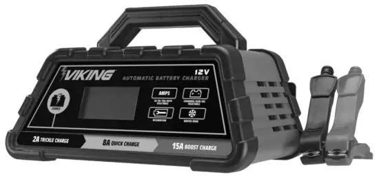
![]() 56796 Microprocessor Controlled Battery Charger
56796 Microprocessor Controlled Battery Charger
Owner’s Manual
Visit our website at: http://www.harborfreight.com
Email our technical support at: [email protected]
Save This Manual Keep this manual for the safety warnings and precautions, assembly, operating, inspection, maintenance, and cleaning procedures. Write the product’s serial number on the back of the manual (or month and year of purchase if the product has no number). Keep this manual and the receipt in a safe and dry place for future reference.
When unpacking, make sure that the product is intact and undamaged. If any parts are missing or broken, please call 1-888-866-5797 as soon as possible.
Copyright© 2022 by Harbor Freight Tools®. All rights reserved.
No portion of this manual or any artwork contained herein may be reproduced in any shape or form without the express written consent of Harbor Freight Tools.
Diagrams within this manual may not be drawn proportionally. Due to continuing improvements, the actual product may differ slightly from the product described herein.
Tools required for assembly and service may not be included.

Read this material before using this product.
Failure to do so can result in serious injury.
SAVE THIS MANUAL.
WARNING SYMBOLS AND DEFINITIONS
| This is the safety alert symbol. It is used to alert you to potential personal injury hazards. Obey all safety messages that follow this symbol to avoid possible injury or death. | |
 |
Indicates a hazardous situation that, if not avoided, will result in death or serious injury. |
|
Indicates a hazardous situation that, if not avoided, could result in death or serious injury. |
 |
Indicates a hazardous situation that, if not avoided, could result in minor or moderate injury. |
 |
Addresses practices not related to personal injury. |
| VAC | Volts Alternating Current |
| A | Amperes |
| CCA | Cold Cranking Amps |
| RC | Reserve Capacity |
| Ah | Ampere-hours |
| WARNING marking concerning Risk of Eye Injury. Wear ANSI-approved splash-resistant safety goggles. |
|
| Read the manual before set-up and/or use. | |
| WARNING marking concerning Risk of Fire. Follow the connection procedure. |
IMPORTANT SAFETY INSTRUCTIONS
- SAVE THESE INSTRUCTIONS –
This manual contains important safety and operating instructions for this battery charger. - Do not expose the charger to rain or snow.
- Use of an attachment not recommended or sold by the battery charger manufacturer may result in a risk of fire, electric shock, or injury to persons.
- To reduce the risk of damage to the electric plug and cord, pull by the plug rather than the cord when disconnecting the charger.
- An extension cord should not be used unless absolutely necessary. The use of an improper extension cord could result in a risk of fire and electric shock.
If an extension cord must be used, make sure:
a. That pins on the plug of the extension cord are the same number, size, and shape as those of the plug on the charger;
b. That extension cord is properly wired and in good electrical condition; and
c. That wire size is large enough for the AC ampere rating of the charger as specified in Table A.Table A: Recommended minimum AWG size for extension cords for battery chargers AC input rating, amperes* AWG size of the cord Length of cord, feet Equal to or
greater thanBut less
than25 50 100 150 0 2 18 18 18 16 2 3 18 18 16 14 3 4 18 18 16 14 4 5 18 18 14 12 5 6 18 16 14 12 6 8 18 16 12 10 8 10 18 14 12 10 10 12 16 14 10 8 12 14 16 12 10 8 14 16 16 12 10 8 16 18 14 12 8 8 18 20 14 12 8 6 * If the input rating of a charger is given in watts rather than in amperes, the corresponding ampere rating is to be determined by dividing the wattage rating by the voltage rating — for example:
1250 watts/125 volts = 10 amperesDo not operate the charger with a damaged cord or plug – replace the cord or plug immediately.
- Do not operate the charger if it has received a sharp blow, been dropped, or otherwise damaged in any way; take it to a qualified serviceman.
- Do not disassemble the charger; take it to a qualified serviceman when service or repair is required. Incorrect reassembly may result in a risk of electric shock or fire.
- To reduce the risk of electric shock, unplug the charger from the outlet before attempting any maintenance or cleaning. Turning off controls will not reduce this risk.
- WARNING – RISK OF EXPLOSIVE GASES.
a. WORKING IN VICINITY OF A LEAD-ACID BATTERY IS DANGEROUS. BATTERIES GENERATE EXPLOSIVE GASES DURING NORMAL BATTERY OPERATION. FOR THIS REASON, IT IS OF UTMOST IMPORTANCE THAT YOU FOLLOW THE INSTRUCTIONS EACH TIME YOU USE THE CHARGER.
b. To reduce the risk of battery explosion, follow these instructions and those published by the battery manufacturer and the manufacturer of any equipment you intend to use in vicinity of the battery. Review cautionary marking on these products and on engines. - PERSONAL PRECAUTIONS
a. Consider having someone close enough by to come to your aid when you work near a lead-acid battery.
b. Have plenty of fresh water and soap nearby in case battery acid contacts skin, clothing, or eyes.
c. Wear complete eye protection and clothing protection. Avoid touching your eyes while working near the battery.
d. If battery acid contacts skin or clothing, wash immediately with soap and water. If acid enters the eye, immediately flood the eye with running cold water for at least 10 minutes and get medical attention immediately.
e. NEVER smoke or allow a spark or flame in the vicinity of the battery or engine.
f. Be extra cautious to reduce the risk of dropping a metal tool onto the battery. It might spark or short-circuit battery or another electrical part that may cause an explosion.
g. Remove personal metal items such as rings, bracelets, necklaces, and watches when working with a lead-acid battery.
A lead-acid battery can produce a shortcircuit current high enough to weld a ring or the like to metal, causing a severe burn.
h. Use charger for charging a LEAD-ACID battery only. It is not intended to supply power to a low voltage electrical system other than in a starter-motor application. Do not use battery charger for charging dry-cell batteries that are commonly used with home appliances.
These batteries may burst and cause injury to persons and damage to property.
i. NEVER charge a frozen battery. - PREPARING TO CHARGE
a. If necessary to remove the battery from the vehicle to charge, always remove the grounded terminal from the battery first. Make sure all accessories in the vehicle are off, so as not to cause an arc.
b. Be sure the area around the battery is well ventilated while the battery is being charged.
c. Clean battery terminals. Be careful to keep corrosion from coming in contact with the eyes.
d. Add distilled water in each cell until battery acid reaches the level specified by the battery manufacturer. Do not overfill. For a battery without removable cell caps, such as valve-regulated lead-acid batteries, carefully follow the manufacturer’s recharging instructions.
e. Study all battery manufacturer’s specific precautions while charging and recommended rates of charge.
f. Determine the voltage of the battery by referring to the vehicle owner’s manual and make sure it matches the output rating of the battery charger.
If the charger has an adjustable charge rate, charge the battery initially at the lowest rate. - CHARGER LOCATION
a. Locate charger as far away from battery as DC cables permit.
b. Never place charger directly above battery being charged; gases from battery will corrode and damage charger.
c. Never allow battery acid to drip on charger when reading electrolyte specific gravity or filling battery.
d. Do not operate the charger in a closed-in area or restrict ventilation in any way.
e. Do not set a battery on top of the charger. - DC CONNECTION PRECAUTIONS
a. Connect and disconnect DC output clips only after setting any charger switches to the “off” position and removing the AC cord from the electric outlet.
Never allow clips to touch each other.
b. Attach clips to battery and chassis as indicated in 15(e), 15(f), and 16(b) through 16(d). - FOLLOW THESE STEPS WHEN BATTERY IS INSTALLED IN THE VEHICLE. A SPARK NEAR THE BATTERY MAY CAUSE A BATTERY EXPLOSION.
TO REDUCE THE RISK OF A SPARK NEAR THE BATTERY:
a. Position AC and DC cables to reduce the risk of damage by the hood, door, or moving engine part.
b. Stay clear of fan blades, belts, pulleys, and other parts that can cause injury to persons.
c. Check the polarity of battery posts. POSITIVE (POS, P, +) battery post usually has a larger diameter than NEGATIVE (NEG, N,–) post.
d. Determine which post of the battery is grounded (connected) to the chassis. If the negative post is grounded to the chassis (as in most vehicles), see (e). If the positive post is grounded to the chassis, see (f).
e. For negative-grounded vehicle, connect POSITIVE (RED) clip from battery charger to POSITIVE (POS, P, +) ungrounded post of the battery. Connect NEGATIVE (BLACK) clip to vehicle chassis or engine block away from the battery. Do not connect the clip to the carburetor, fuel lines, or sheet-metal body parts. Connect to a heavy gauge metal part of the frame or engine block.
f. For a positive-grounded vehicle, connect the NEGATIVE (BLACK) clip from the battery charger to the NEGATIVE (NEG, N, –) ungrounded post of the battery. Connect POSITIVE (RED) clip to vehicle chassis or engine block away from the battery.
Do not connect the clip to the carburetor, fuel lines, or sheet-metal body parts. Connect to a heavy gauge metal part of the frame or engine block.
g. When disconnecting the charger, disconnect the AC cord, remove the clip from the vehicle chassis, and then remove the clip from the battery terminal.
h. See operating instructions for length of charge information. - FOLLOW THESE STEPS WHEN BATTERY IS OUTSIDE THE VEHICLE. A SPARK NEAR THE BATTERY MAY CAUSE A BATTERY EXPLOSION.
TO REDUCE THE RISK OF A SPARK NEAR THE BATTERY:
a. Check the polarity of battery posts. POSITIVE (POS, P, +) battery post usually has a larger diameter than NEGATIVE (NEG, N, –) post.
b. Attach at least a 24-inch-long 6-gauge (AWG) insulated battery cable to the NEGATIVE (NEG, N, –) battery post.
c. Connect the POSITIVE (RED) charger clip to the POSITIVE (POS, P, +) post of the battery.
d. Position yourself and a free end of cable as far away from the battery as possible –then connect a NEGATIVE (BLACK) charger clip to the free end of the cable.
e. Do not face battery when making final connection.
f. When disconnecting the charger, always do so in reverse sequence of connecting procedure and break first connection while as far away from battery as practical.
g. A marine (boat) battery must be removed and charged onshore. To charge it on board requires equipment specially designed for marine use.  Wear ANSI-approved splash-resistant safety goggles and heavy-duty rubber work gloves whenever connecting, disconnecting, or working near battery acid can cause permanent blindness.
- Maintain labels and nameplates on the charger. These carry important safety information. If unreadable or missing, contact Harbor Freight Tools for a replacement.
- This product is not a toy. Keep it out of reach of children.
- Unplug the Battery Charger from its electrical outlet before connecting its cables to a battery, or performing any inspection, maintenance, or cleaning procedures.
- Use this Charger with flooded lead-acid batteries only. Do not overcharge a maintenance-free battery.
- Do not attempt to charge non-rechargeable or defective batteries.
- Do not charge more than one battery at one time.
- Has your charger been serviced by a qualified repair person using only identical replacement parts?
This will ensure that the safety of the charger is maintained. - Do not use the charger while you are tired or under the influence of drugs, alcohol or medication.
A moment of inattention while operating charger may result in serious personal injury. - Before moving the charger, disconnect the power supply and battery, then allow the charger to cool.
- People with pacemakers should consult their physician(s) before use. Electromagnetic fields in close proximity to heart pacemakers could cause pacemaker interference or pacemaker failure.
In addition, people with pacemakers should:
• Avoid operating alone.
• Properly maintain and inspect to avoid electrical shock.
• Properly ground power cord. Ground Fault Circuit Interrupter (GFCI) should also be implemented – it prevents sustained electrical shock. - The warnings, precautions, and instructions discussed in this instruction manual cannot cover all possible conditions and situations that may occur. It must be understood by the operator that common sense and caution are factors that cannot be built into this product but must be supplied by the operator.
![]() SAVE THESE INSTRUCTIONS.
SAVE THESE INSTRUCTIONS.
Grounding and AC Power Cord Connection Instructions
The charger should be grounded to reduce the risk of electric shock. The plug must be plugged into an outlet that is properly installed and grounded in accordance with all local codes and ordinances.
DANGER – Never alter the AC cord or plug provided –if it will not fit the outlet, have a proper outlet installed by a qualified electrician. Improper connection can result in a risk of an electric shock.
Specifications
| Electrical Rating | 120!VAC / 60!Hz / 3.5!A |
| Charge Settings* | 2!A / 8!A / 15!A |
| Battery Cables | 6′, 14 AWG Red = Positive Black = Negative |
| Power Cord | 6′ |
*Amperage is only present while connected to a battery.
Setup
![]() Read the ENTIRE IMPORTANT SAFETY INFORMATION section at the beginning of this manual including all text under subheadings therein before set up or use of this product.
Read the ENTIRE IMPORTANT SAFETY INFORMATION section at the beginning of this manual including all text under subheadings therein before set up or use of this product.
Controls
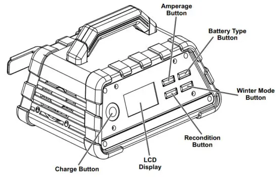
LCD Display: Displays charging status, charging current, voltage, battery type, recondition mode, winter mode, and error codes.
Amperage Button: Use to set the amperage output from 2! A, 8! A, 15!A and automatic charging rate.
Battery Type Button: Use to select the battery type from standard or AGM. For GEL batteries use the standard-setting.
Charge Button: Use to begin charging manually.
Recondition Button: Use to activate the battery reconditioning function for weak, sulfated, or deeply discharged batteries.
Winter Mode Button: Use to activate the winter charging mode in cold weather.
Protection Features:
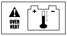
- Overheating protection!–!If the Charger overheats, it will automatically shut off. The charger will automatically resume when it has cooled down.
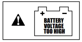
- Reverse polarity!–!if the cables are connected incorrectly, the Charger will not function, and the LCD screen displays a reverse polarity error code.
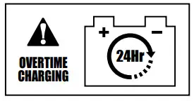
- Overcharging protection!–!if the battery cannot be fully charged within 24 hours, Charger will stop charging automatically.
Operating Instructions
![]() Read the ENTIRE IMPORTANT SAFETY INFORMATION section at the beginning of this manual including all text under subheadings therein before set up or use of this product.
Read the ENTIRE IMPORTANT SAFETY INFORMATION section at the beginning of this manual including all text under subheadings therein before set up or use of this product.
TO PREVENT SERIOUS INJURY:
DO NOT PLUG IN CHARGER UNTIL DIRECTED TO DO SO.
Use this Charger only on AGM, GEL, and standard lead-acid batteries.
Other batteries may be damaged or may overheat, leak, or catch fire.
Preparing to Charge
![]() TO PREVENT SERIOUS INJURY:
TO PREVENT SERIOUS INJURY:
Wear ANSI-approved splash-resistant safety goggles and heavy-duty rubber work gloves whenever connecting, disconnecting, or working near the battery.
Battery acid can cause permanent blindness.
- If necessary to remove the battery from the vehicle to charge, always remove the grounded terminal from the battery first. Make sure all accessories in the vehicle are off, so as not to cause an arc.
- Make sure the area around the battery is well ventilated while the battery is being charged.
- Clean battery terminals. Be careful to keep corrosion from coming in contact with the eyes.
- With standard lead-acid batteries, add distilled water in each cell until battery acid reaches the level specified by the battery manufacturer.
Do not overfill. For sealed batteries without removable cell caps, such as AGM, GEL, or valve-regulated lead-acid batteries, carefully follow the manufacturer’s recharging instructions. - Study all battery manufacturer’s specific precautions while charging and recommended rates of charge.
- Determine voltage of battery by referring to vehicle owner’s manual and make sure it matches output rating of battery Charger. If Charger has adjustable charge rate, charge the battery initially at the lowest rate.
- A marine (boat) battery must be removed and charged on shore. To charge it on board requires equipment specially designed for marine use.
Charger Location
- Locate Charger as far away from the battery as DC cables permit.
- Never place charger directly above battery being charged; gases from battery will corrode and damage charger.
- Never allow battery acid to drip on the charger when reading electrolyte specific gravity or filling the battery.
- Do not operate the charger in a closed-in area or restrict ventilation in any way.
- Do not set a battery on top of the Charger.
Charging Battery Installed in Vehicle
A SPARK NEAR THE BATTERY MAY CAUSE A BATTERY EXPLOSION.
TO REDUCE THE RISK OF A SPARK NEAR THE BATTERY FOLLOW THESE INSTRUCTIONS EXACTLY.
![]() TO PREVENT SERIOUS INJURY:
TO PREVENT SERIOUS INJURY:
Wear ANSI-approved splash-resistant safety goggles and heavy-duty rubber work gloves whenever connecting, disconnecting, or working near the battery.
Battery acid can cause permanent blindness.
- Position AC and DC cables to reduce the risk of damage to the hood, door, or moving engine part.
- Stay clear of fan blades, belts, pulleys, and other parts that can cause injury to persons.
- Check the polarity of battery posts. POSITIVE (POS, P, +) battery post usually has a larger diameter than NEGATIVE (NEG, N,–) post.
- Determine which post of the battery is grounded (connected) to the chassis. If the negative post is grounded to the chassis (as in most vehicles), see 5.
If the positive post is grounded to the chassis, see 6. - For negative-grounded vehicles, connect the POSITIVE (RED) clamp from Battery Charger to the POSITIVE (POS, P, +) ungrounded post of the battery.
Connect NEGATIVE (BLACK) clamp to vehicle chassis or engine block away from the battery.
Do not connect the clamp to the carburetor, fuel lines, or sheet-metal body parts. Connect to a heavy gauge metal part of the frame or engine block. - For a positive-grounded vehicle, connect NEGATIVE
(BLACK) clamp from Battery Charger to NEGATIVE
(NEG, N, –) ungrounded post of the battery. Connect
POSITIVE (RED) clamp to vehicle chassis or engine block away from the battery. Do not connect the clamp to the carburetor, fuel lines, or sheet metal body parts. Connect to a heavy gauge metal part of the frame or engine block. - When disconnecting the charger, disconnect AC cord, remove the clamp from vehicle chassis, and then remove the clamp from the battery terminal.
- After use clean, then store the Charger indoors out of children’s reach.
Charging Battery Outside Vehicle
A SPARK NEAR THE BATTERY MAY CAUSE A BATTERY EXPLOSION.
TO REDUCE THE RISK OF A SPARK NEAR THE BATTERY FOLLOW THESE INSTRUCTIONS EXACTLY.
![]() TO PREVENT SERIOUS INJURY:
TO PREVENT SERIOUS INJURY:
Wear ANSI-approved splash-resistant safety goggles and heavy-duty rubber work gloves whenever connecting, disconnecting, or working near the battery.
Battery acid can cause permanent blindness.
- Check the polarity of battery posts. POSITIVE (POS, P, +) battery post usually has a larger diameter than NEGATIVE (NEG, N, –) post.
- Attach at least a 24-inch-long 6-gauge (AWG) insulated battery cable to the NEGATIVE (NEG, N, –) battery post.
- Connect the POSITIVE (RED) charger clamp to the POSITIVE (POS, P, +) post of the battery.
- Position yourself and the free end of the cable as far away from the battery as possible!–!then connect the NEGATIVE (BLACK) charger clamp to the free end of the cable.
- Do not face battery when making the final connection.
- When disconnecting the charger, always do so in reverse sequence of connecting procedure and break the first connection while as far away from the battery as practical.
- After use clean, then store the Charger indoors out of children’s reach.
Operation
A SPARK NEAR THE BATTERY MAY CAUSE A BATTERY EXPLOSION.
TO REDUCE THE RISK OF A SPARK NEAR THE BATTERY FOLLOW THESE INSTRUCTIONS EXACTLY.
![]() TO PREVENT SERIOUS INJURY:
TO PREVENT SERIOUS INJURY:
Wear ANSI-approved splash-resistant safety goggles and heavy-duty rubber work gloves whenever connecting, disconnecting, or working near the battery.
Battery acid can cause permanent blindness.
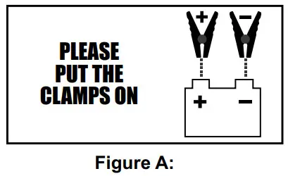
- Follow the directions on page 8 to connect Charger to the battery, then plug the Power Cord into a properly grounded outlet. If the cable clamps are not connected or the connection is loose, the LCD screen will display as shown in Figure A:
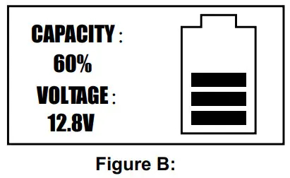
- When a good connection has been made, the LCD screen will display the battery capacity and voltage. See the example in Figure B:
- Press the “AMP” button to choose the desired charging rate!–!if unsure select the automatic charging rate. Press the “BATTERY TYPE” button to select battery type!–!for GEL batteries select “STD”!–!then press the “CHARGE” button to start charging. The LCD screen will display the settings. See the example in Figure C:
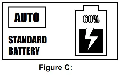 Note: If the user does not select the charging amp and battery type settings within 30 seconds, Charger will start charging the battery using the default setting!–!automatic charging rate for standard battery.
 - Once the battery is fully charged the charger automatically switches to a float charge/maintenance mode.
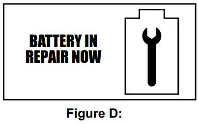
- For weak/sulfated batteries or batteries that have been unused for long periods of time, the battery reconditioning function may be used to recover the battery from deep discharge and help the
battery last longer. Press the “RECONDITION” button to activate this function. The LCD screen will display as shown in Figure D:
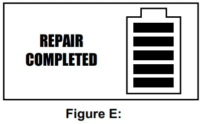
- When the reconditioning process is finished, the LCD screen will display as shown in Figure E: and the Charger will return to normal charge mode.
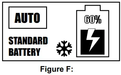
- The winter charging mode may be used for specialized battery charging in winter weather conditions. To enter this mode, press the “WINTER” button at any stage in the charging process.
A snowflake icon will appear on the LCD screen display indicating Charger is in the winter charging mode. See the example in Figure F: Pressing the “WINTER” button again will exit the winter charging mode.
Maintenance Instructions
Procedures not specifically explained in this manual must be performed only by a qualified technician.
TO PREVENT SERIOUS INJURY: Unplug the Charger, disconnect any battery, and allow Charger to cool completely before performing any inspection, maintenance, or cleaning procedures.
TO PREVENT SERIOUS INJURY FROM TOOL FAILURE:
Do not use damaged equipment. If abnormal noise or vibration occurs, have the problem corrected before further use.
- BEFORE EACH USE, inspect the general condition of the Charger. Check for:
• loose hardware
• cracked or broken parts
• damaged electrical wiring or cable insulation
• any other condition that may affect its safe operation. - AFTER USE, wipe the external surfaces of the tool with a clean cloth.
 CAUTION! The charger is damaged, it must be replaced only by a qualified service technician.
DO NOT OPEN THE CHARGER HOUSING, NO USER-SERVICEABLE PARTS INSIDE.
Troubleshooting Error Codes
| Error Code | Possible Causes | Likely Solutions |
 |
Clamps connected to the wrong terminals on the battery. | Correct clamp connections on the battery. |
 |
The Charger is overheating. | Make sure the air vents on Charger are clear. The charger will automatically resume charging when it has cooled down. |
 |
The charger may be connected to a 24V battery. | Verify battery being charged is 12V. |
 |
1. An appliance is drawing power from the battery being charged. 2. Selected charging rate is too low for battery rating. |
1. Disconnect the appliance and charge the battery again. 2. Select a higher charging rate and continue charging the battery. |
 |
A defective battery, will not hold a full charge. | Has the battery been checked by a qualified technician? Replace the battery if necessary. |
Record Product’s Serial Number Here:
Note: If the product has no serial number, record the month and year of purchase instead.
Note: Internal parts are not user-serviceable and are not available.
Limited 90 Day Warranty
Harbor Freight Tools Co. makes every effort to assure that its products meet high quality and durability standards, and warrants to the original purchaser that this product is free from defects in materials and workmanship for the period of 90 days from the date of purchase. This warranty does not apply to damage due directly or indirectly, to misuse, abuse, negligence or accidents, repairs or alterations outside our facilities, criminal activity, improper installation, normal wear and tear, or to lack of maintenance. We shall in no event be liable for death, injuries to persons or property, or for incidental, contingent, special or consequential damages arising from the use of our product. Some states do not allow the exclusion or limitation of incidental or consequential damages, so the above limitation of exclusion may not apply to you. THIS WARRANTY IS EXPRESSLY IN LIEU OF ALL OTHER WARRANTIES, EXPRESS OR IMPLIED, INCLUDING THE WARRANTIES OF MERCHANTABILITY AND FITNESS.
To take advantage of this warranty, the product or part must be returned to us with transportation charges prepaid. Proof of purchase date and an explanation of the complaint must accompany the merchandise. If our inspection verifies the defect, we will either repair or replace the product at our election or we may elect to refund the purchase price if we cannot readily and quickly provide you with a replacement. We will return repaired products at our expense, but if we determine there is no defect, or that the defect resulted from causes not within the scope of our warranty, then you must bear the cost of returning the product.
This warranty gives you specific legal rights and you may also have other rights which vary from state to state.
![]()
Note: This equipment has been tested and found to comply with the limits for a Class B digital device, pursuant to part 15 of the FCC Rules. These limits are designed to provide reasonable protection against harmful interference in a residential installation.
This equipment generates, uses, and can radiate radio frequency energy and, if not installed and used in accordance with the instructions, may cause harmful interference to radio communications.
However, there is no guarantee that interference will not occur in a particular installation.
If this equipment does cause harmful interference to radio or television reception, which can be determined by turning the equipment off and on, the user is encouraged to try to correct the interference by one or more of the following measures:
- Reorient or relocate the receiving antenna.
- Increase the separation between the equipment and receiver.
- Connect the equipment into an outlet on a circuit different from that to which the receiver is connected.
- Consult the dealer or an experienced radio/TV technician for help.
![]()
26677 Agoura Road • Calabasas, CA 91302 • 1-888-866-5797
]]>
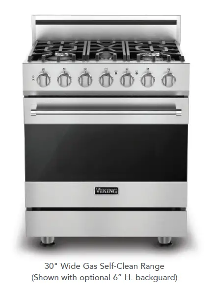
Features and Functions
• Wide variety of BTU ratings to accommodate all types of
surface cooking needs – including a fifth burner
– Left front – 18,000 BTU
– Left rear – 8,000 BTU
– Center – 9,000 BTU
– Right front – 18,000 BTU
– Right rear – 12,000 BTU
• Sealed burners with porcelainized, cast-iron burner caps
• Exclusive – SureSparkTM Ignition System
– Automatic electric spark ignition/re-ignition; surface burners
light at any position on the knob and re-light if extinguished,
even on lowest setting
• Large-capacity oven has six porcelain-coated rack supports and
comes with one TruGlideTM Full Extension Oven Rack
and two standard racks.
• High performance cooking modes include Natural Airflow
Bake, Convection Bake, Broil, Convection Broil, Convection
Dehydrate, and Convection Defrost
• All convection functions utilize the ProFlowTM Convection Air
Baffle; specifically designed to ensure balanced air flow for
even heat distribution

• Exclusive – combination of single 30,000 BTU U-shaped burner
and broiler with SureSparkTM Ignition System
• 15,000 BTU broiler provides intense searing heat for broiling
applications
• Two halogen oven lights for excellent visibility throughout
oven cavity
• Shipped standard with island trim
• Accessory portable griddle/grill (RDPGD) available for use over
center burner
Easy Operation and Cleanup
• Extremely large self-clean convection oven
• Permanently sealed burners – spills cannot enter the onepiece,
tooled and porcelainized burner box
• Durable metal die-cast knobs with child-proof, push-to-turn
safety feature
• Customer-removable knobs, grates, and burners/caps for easy
cleaning
• Continuous grate design for easy movement of pots and pans
Installation Accessories
• 6” high backguard (RD301BG6SS)
• Countertop side trim (RD24CSTSS)
• Countertop rear trim (P30CRTSS)
• Curb base and custom curb base front (P30CBF4SS)
• LP conversion kit (RDLPKR)
Finishes
• Available in Stainless Steel (SS), Black (BK), and White (WH)
Warranty Highlights
• One-year full – complete product
• Ninety-day full – cosmetic parts such as glass, painted items,
and decorative items
• Five-year limited – surface/tube burners
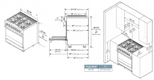
| DESCRIPTION | G A S S E L F – C L E A N 3 0 ” W I D E R A N G E |
| RVGR3302 | |
| Overall Width | 29-7/8” (75.9 cm) |
| Overall Height | To top of side trim – 35-7/8” (91.1 cm) minimum; 37” (94.0 cm) maximum Legs adjust – 1-1/8” (2.9 cm) |
| Overall Depth from Rear | To front of side panel – 25” (63.5 cm) To front of door – 25-3/4” (65.4 cm) To front of control panel – 27-1/8” (68.9 cm) To end of knobs – 29” (73.7 cm) |
| Additions to Overall Height | To top of island trim – add 0” (0.0 cm) To top of 6” h. backguard – add 6” (15.2 cm) To top of high shelf – add 18-3/16” (46.2 cm) |
| Gas Requirements | Ships Natural or LP/Propane; Field convert with conversion kit (purchased separately); accepts standard residential 1/2” (1.3 cm) ID gas service line. |
| Gas Manifold Pressure | Natural 5.0” W.C.P./ Liquid Propane L/P 10.0” W.C.P. |
| Electrical Requirements | 120VAC/60Hz; 4 ft. (121.9 cm), 3-wire cord with grounded 3-prong plug attached to unit |
| Maximum Amp Usage | .74 amps |
| Surface Burner Rating Natural/LP | Left Front: 18,000 BTU Nat./15,800 BTU LP/Propane (5.3 kW Nat./4.7 kW LP/Propane) Left Rear: 8,000 BTU Nat./6,500 BTU LP/Propane (2.3 kW Nat./1.9 kW LP/Propane) Center: 9,000 BTU Nat./8,000 BTU LP/Propane (2.7 kW Nat./2.3 kW LP/Propane) Right Front: 18,000 BTU Nat./15,000 BTU LP/Propane (5.3 kW Nat./4.7 kW LP/Propane) Right Rear: 12,000 BTU Nat./11,000 BTU LP/Propane (3.5 kW Nat./3.2 kW LP/Propane) |
| Oven Interior Width | 23″ (58.4 cm) |
| Oven Interior Height | 16-1/8” (40.9 cm) |
| Oven Interior Depth | Overall – 18-3/4” (47.6 cm) AHAM* – 15-3/8” (39.1 cm) |
| Oven Volume | Overall – 4.0 cu. ft. AHAM* – 3.3 cu. ft. |
| Approximate Shipping Weight | 410 lb. (184.5 kg) |
*The AHAM standard for measuring oven capacity subtracts the doorplug and convection baffle dimension from the total oven volume. Please do not prepare installation from brochure data only. See installation instructions for important clearance/installation information.

VIKING RANGE, LLC 111 FRONT STREET GREENWOOD, MISSISSIPPI 38930 USA
For detailed product information, model numbers, or to request a quote call 1-888-845-4641 or visit vikingrange.com
© 2013 Viking Range, LLC | Specifications subject to change without notice.
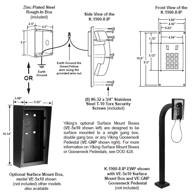
K-1900-8-IP Series
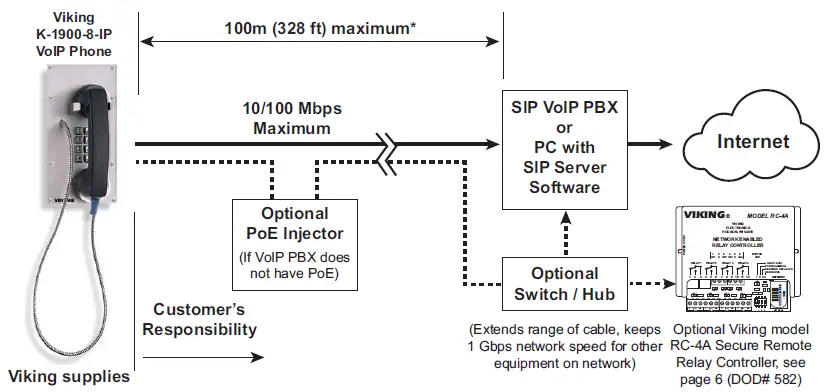
The K-1900-8-IP Series panel phone can either auto-dial a phone number each time the handset is lifted, be used as a multi-number auto-dialer, or be used as a standard manual dial phone. The K-1900-8-IP Series phones are designed to provide quick and reliable communication for SIP VoIP phone systems with PoE. The unit can be programmed from any PC on the same LAN or remotely using a Static IP Address. The K-1900-8-IP Series phone can dial up to 250 programmable numbers and another 250 rollover numbers.
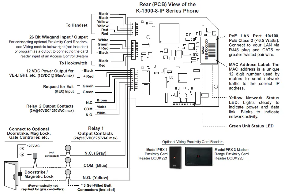
When a call initiated by the K-1900-8-IP Series phone is answered by an apartment or business tenant, a built-in contact closure may be activated to control an electric gate or door strike. Up to 1,000 keyless entry codes may be programmed, providing tenants with keyless entry. A 26 Bit Wiegand input is provided for adding an optional proximity card reader with capacity to program up to 1,000 card numbers. Keyless entry codes and card numbers can be programmed to only allow access at specific times and/or day of the week. A request for exit (REX) input is included for easy exiting. The K-1900-8-IP Series phone also has automatic event logging allowing you to review the time and date of the call, which door was open/closed, what keyless entry code or proximity card was used, request for exit usage and whether it was an inbound or outbound call.
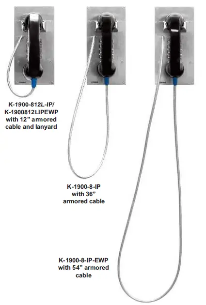
The K-1900-812L-IP and K-1900812LIPEWP have a 12” long armored cable with internal stainless steel lanyard for additional cable strength.
The K-1900-8-IP-EWP and K-1900812LIPEWP shares all of the features of the K-1900-8-IP and K-1900-812L-IP in addition to Enhanced Weather Protection (EWP) for outdoor installations where the unit is exposed to precipitation or condensation. EWP products are designed to meet IP66 standards and may feature foam rubber gaskets, sealed connections, gel-filled butt connectors, as well as potted circuit boards with internally sealed, field-adjustable trim pots and DIP switches for easy on-site programming. For more information on EWP, see DOD 859.
Features
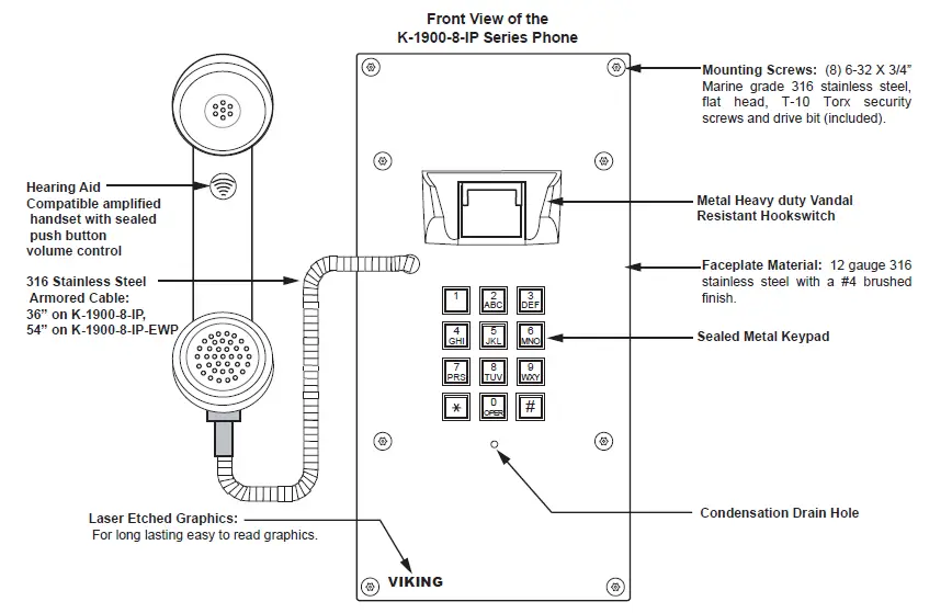
- Vandal Resistant Features: 12 gauge 316 stainless steel faceplate with permanent laser etched graphics. Heavy duty metal keypad, hook switch, armored cable and T-10 security Torx drive mounting screws.
- Weather Resistant Features: Marine grade 316 stainless steel faceplate and Torx security screws. Internally sealed keypad. Faceplate gaskets (on EWP models).
- Ring with adjustable volume and cadence
- Hearing aid compatible amplified handset with sealed push button volume control
- Two sets of SPDT 2 Amp relay contacts for door/gate or camera control
- Optional RC-4A for Secure Remote Relay Control, see DOD 582
- SIP compliant (see page 2 for list of compatible IP-PBX phone systems)
- PoE powered (class 2, <6.5 Watts)
- Outbound Proxy, Authentication ID, Peer to Peer, VLAN Tagging
- Network downloadable firmware
- K-1900-812L-IP and K-1900812LIPEWP: 12” armored handset cable
- K-1900-8-IP: 36” armored handset cable
- K-1900-8-IP-EWP: 54” armored handset cable
- Programmable to speed dial up to 250 numbers
- 26 Bit Wiegand input for optional proximity card readers, see DOD 221 and 228
- 26 Bit Wiegand output connect to card reader input of an Access Control System
- Cycles to rollover phone number on busy or no-answer
- Program up to 1,000 keyless entry codes and/or proximity card numbers
- Keyless entry codes and proximity card numbers can be programmed to only allow access at specific times and day of week
- Event logging with time and date stamp
- Optional Enhanced Weather Protection (EWP), EWP products are designed to meet IP66 Ingress Protection Rating, see DOD 859
- Remotely programmable
- Extended temperature range (-40°F to 140°F)
- Flush mount with included steel rough-in box, or use an optional VE-5×10 surface mount box (not included, see DOD 424)
- Optional VE-LIGHT kit to illuminate the front panel at night, see DOD 428
- Diagnostics (for testing relays)
Applications
- Apartment Entry Phone
- Commercial Gate Entrance
- Courtesy Assistance Phone
- Customer Service Phone
- Hot-Line Phone
- Door Entry Phone
- Kiosk Phone with up to 250 number speed dialing
- Use with Viking PRX-1 (DOD 221) or PRX-3 (DOD 228) Proximity Card Readers
- Use with Viking LRT-4 Long Range Transmitter (DOD 226)
Specifications
- Power: PoE class 2 (<6.5 Watts)
- Dimensions for K-1900-8-IP and K-1900-812L-IP Models
- Phone only: 5.0” x 10.0” x 4.68” (127mm x 254mm x 119mm)
- Including rough-in box: 5.0” x 10.0” x 5.53” (127mm x 254mm x 141mm)
- Dimensions for K-1900-8-IP-EWP and K-1900812LIPEWP Models
- Phone only: 5.0” x 10.0” x 4.75” (127mm x 254mm x 121mm)
- Including rough-in box: 5.0” x 10.0” x 5.61” (127mm x 254mm x 143mm)
- Shipping Weight for K-1900-8-IP and K-1900-8-IP-EWP: 5.3 lbs (2.4 kg)
- Shipping Weight for K-1900-812L-IP and K-190012L8IPEWP: 5.3 lbs (2.4 kg)
- Operating Temperature: -40°F to 140°F (-40° C to 60° C)
- Humidity – Standard Models: 5% to 95% non-condensing
- Humidity – EWP Models: Up to 100%
- Handset Cable Length on K-1900-812L-IP and K-1900812LIPEWP Models: 12” to 12.7” (31 cm to 33 cm)
- Handset Cable Length on K-1900-8-IP Model: 34” to 37” (86 cm to 94 cm)
- Handset Cable Length on K-1900-8-IP-EWP Model: 52” to 57” (132 cm to 145 cm)
- Audio Codecs: G711u, G711a, G722
- Network Compliance: IEEE 802.3 af PoE, SIP 2.0 RFC3261, 100BASE-TX with auto cross over
- Regulatory Compliance: CE, FCC Part 15 and Canada ICES-003 Class A
- Connections: (1) RJ45 10/100 Base-T, (14) gel-filled butt connectors
VoIP SIP System Compatibility
For compatibility and vendor specific detailed configuration instructions, see the Viking VoIP SIP System Compatibility List, DOD 944. To open and download this PDF file:
Scan the QR code below to open and download the Viking VoIP SIP System Compatibility List
– OR –
- Go to www.vikingelectronics.com and enter 944 in the search box
- Click Application Note (DOD 944) to open and download the PDF

Important: Exclusion from this list means only that compatibility has not been verified, it does not mean incompatibility. If you have questions, please call Viking Electronics at 715-386-8861.
Definitions
Client: A computer or device that makes use of a server. As an example, the client might request a particular file from the server.
DHCP: Dynamic Host Configuration Protocol. In this procedure the network server or router takes note of a client’s MAC address and assigns an IP address to allow the client to communicate with other devices on the network.
DNS Server: A DNS (Domain Name System) server translates domain names (ie: www.vikingelectronics.com) into an IP address.
Ethernet: Ethernet is the most commonly used LAN technology. An Ethernet Local Area Network typically uses twisted pair wires to achieve transmission speeds up to 1Gbps.
Host: A computer or device connected to a network.
Host Name: A host name is a label assigned to a device connected to a computer network that is used to identify the device in various forms of network communication.
Hosts File: A file stored in a computer that lists host names and their corresponding IP addresses with the purpose of mapping addresses to hosts or vice versa.
Internet: A worldwide system of computer networks running on IP protocol which can be accessed by individual computers or networks.
IP: Internet Protocol is the set of communications conventions that govern the way computers communicate on networks and on the Internet.
IP Address: This is the address that uniquely identifies a host on a network.
LAN: Local Area Network. A LAN is a network connecting computers and other devices within an office or building.
Lease: The amount of time a DHCP server reserves an address it has assigned. If the address isn’t used by the host for a period of time, the lease can expire and the address can be assigned to another host.
MAC Address: MAC stands for Media Access Control. A MAC address, also called a hardware address or physical address, is a unique address assigned to a device at the factory. It resides in the device’s memory and is used by routers to send network traffic to the correct IP address. You can find the MAC address of your K-1900-8-IP phone printed on a white label on the top surface of the PoE LAN port.
Router: A device that forwards data from one network to another. In order to send information to the right location, routers look at IP Address, MAC Address and Subnet Mask.
RTP: Real-Time Transport Protocol is an Internet protocol standard that specifies a way for programs to manage the real-time transmission of multimedia data over either unicast or multicast network services.
Server: A computer or device that fulfills requests from a client. This could involve the server sending a particular file requested by the client.
Session Initiation Protocol (SIP): Is a signaling communications protocol, widely used for controlling multimedia communication sessions such as voice and video calls over Internet Protocol (IP) networks. The protocol defines the messages that are sent between endpoints, which govern establishment, termination and other essential elements of a call.
Static IP Address: A static IP Address has been assigned manually and is permanent until it is manually removed. It is not subject to the Lease limitations of a Dynamic IP Address assigned by the DHCP Server. The default static IP Address is: 192.168.154.1
Subnet: A portion of a network that shares a common address component. On TCP/IP networks, subnets are defined as all devices whose IP addresses have the same prefix. For example, all devices with IP addresses that start with 100.100.100. would be part of the same subnet. Dividing a network into subnets is useful for both security and performance reasons. IP networks are divided using a subnet mask.
TCP/IP: Transmission Control Protocol/Internet Protocol is the suite of communications protocols used to connect hosts on the Internet. TCP/IP uses several protocols, the two main ones being TCP and IP. TCP/IP is built into the UNIX operating system and is used by the Internet, making it the de facto standard for transmitting data over networks.
TISP: Telephone Internet Service Provider
WAN: Wide Area Network. A WAN is a network comprising a large geographical area like a state or country. The largest WAN is the Internet.
Wireless Access Point (AP): A device that allows wireless devices to connect to a wired network using Wi-Fi, or related standards. The AP usually connects to a router (via a wired network) as a standalone device, but it can also be an integral component of the router itself.
Wireless Repeater (Wireless Range Extender): takes an existing signal from a wireless router or access point and rebroadcasts it to create a second network. When two or more hosts have to be connected with one another over the IEEE 802.11 protocol and the distance is too long for a direct connection to be established, a wireless repeater is used to bridge the gap.
Features Overview

Note: The gel-filled (water-tight) butt connectors are designed for insulation displacement on 19-26 gauge wire with a maximum insulation of 0.082 inches
Installation and Mounting
IMPORTANT: Electronic devices are susceptible to lightning and power station electrical surges from both the AC outlet and the telephone line. It is recommended that a surge protector be installed to protect against such surges.
To install the K-1900-8-IP Series panel phone, attach the phone panel using the provided screws or surface mount using any of Viking’s VE-5×10 Series surface mount boxes (DOD 424). Note: Four extra screws and nuts are provided to fill the unused mounting holes.
Viking’s optional Surface Mount Boxes (model VE-5×10 shown below) are designed to be surface mounted to a wall, post, single gang box or a Viking gooseneck pedestal (model VE-GNP shown below). The K-1900-8-IP Series phone can also be mounted in an optional VE-9×20 Weatherproof Enclosure, not shown (DOD 413).
Note: When mounting a K-1900-8-IP-EWP in an optional VE-9×20 Weatherproof Enclosure (not shown), the length of the handset cable must be reduced. Use a 3/32” hex key or bit to loosen the set screw in the brass handset cable retainer. Pull approximately 18 inches of the cable through the panel and retighten the set screw.
Important: Write down the MAC Address (on the RJ-45 jack) as this may be needed to identify the unit after installation.
Typical Installation on SIP Based VoIP Phone System
Note: A PoE extender can be used for an additional 100 meters per extender. For longer runs (up to 2 km / 1.2 miles) a ethernet to fiber media converter can be used.
PC Requirements
- IBM compatible personal computer with: Windows 7, 8 or 10
- Adobe Acrobat Reader 8 or higher
- K-1900-8-IP hardware
- Available LAN with PoE (class 2, <6.5 watts)
- Ethernet cable ( CAT5 min.)
- 1 MB minimum free hard drive space for installation
- 16MB of free physical RAM
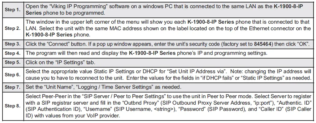
PC Programming
Download and install the programming software
- Go to www.vikingelectronics.com and enter K-1900-8-IP or K-1900-812L-IP in the search box
- Click K-1900-8-IP or K-1900-812L-IP in the search results
- Scroll down the page to Downloads, click IP Programming Software
- Install the programming software by saving or opening the file and then clicking on setup Viking IP Programming.exe
- Follow the prompts on your screen to complete software installation.
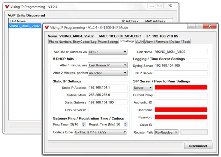
- To start the Viking IP Programming application, click on the Viking IP Programming icon on your desk top. The Main screen will appear, allowing the user to program any K-1900-8-IP Series connected to that LAN.
Note: PC must be connected to the same LAN as the K-1900-8-IP Series.
A. Manually Muting SIP/Network Failure Alarm Beeps (3 beeps repeated every 30 seconds)
With the unit connected and powered (Green LED on and Yellow LED off or blinking) it will output 3 beeps every 30 seconds in the handset of the K-1900-8-IP Series indicating a SIP registration failure, failure to receive an echo reply from a pinged gateway or Ethernet connection failure. You can manually disable the beeps by pressing and holding the “ * ” button for 5 seconds (2 beeps will then be heard) or by clicking the “Mute Alarm Until Next Failure” tab in the Viking VoIP programming software. The LED will continue to flash allowing you to trouble shoot the failure.
B. Connect / Disconnect
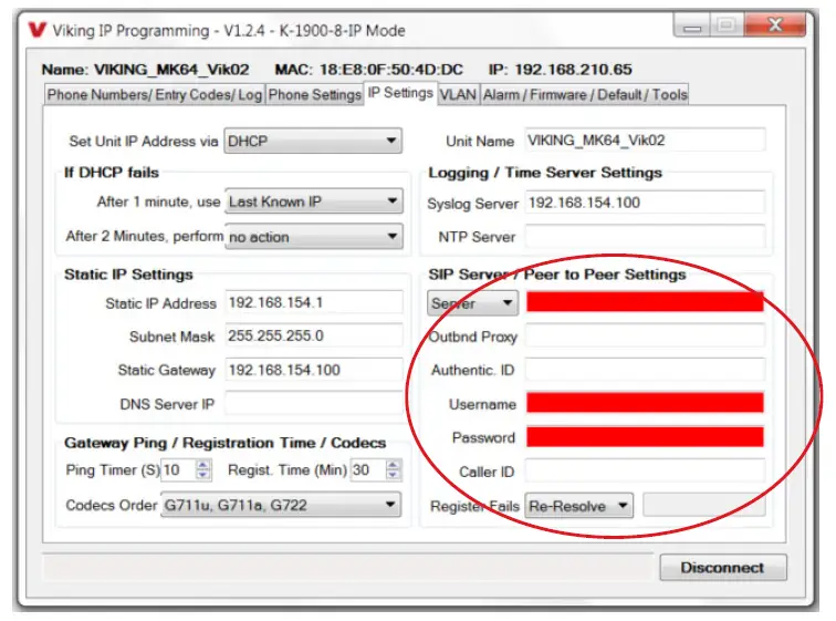
Open the “Viking IP Programming” software on the PC and the start screen shown below will appear. Any Viking IP phones that are connected to the network will appear on the list. Simply select the K-1900-8-IP Series on the list and click on the “Connect” button at the bottom or double click the selected phone. If the security code of the selected phone is still set to default (845464), the PC software will not require entering a security code to connect to the phone. K-1900-8-IP Series have a default name of “VIKING_MK64_Vik02”, so if many phones are connected to the same network that all have the default name, MAC addresses must be used to identify each phone.
When finished programming, click on the “Disconnect” button at the bottom. Closing the program will also automatically disconnect the unit.
C. Configuring the K-1900-8-IP Network Settings
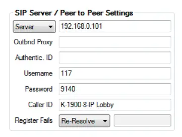
Example 1: On-Premise SIP Phone System (Panasonic TDE 100/200)
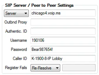
Example 2: Cloud Based Service Provider (Voip.ms)
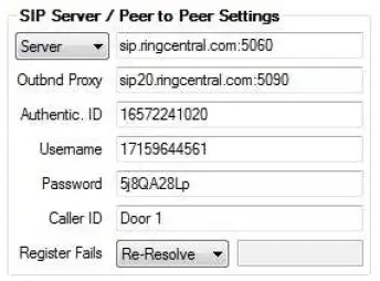
Example 3: Cloud Based Service Provider requiring Outbound Proxy and Authentication ID (Ring Central)
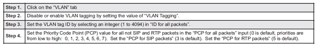
D. Configuring K-1900-8-IP VLAN Settings
E. Manually Resetting the Security Code to Enter Programming
F. Manually Resetting All Network Parameters to Factory Default
*Note: if you do not go back on-hook within 6 seconds, the handset will continue to beep until back on-hook. This indicates an error and network parameters will remain unchanged.
Programming Features
1. Unit Name
Up to a 31 character unit name can be assigned to the K-1900-8-IP Series Phone being programmed.
2. SIP Server
Enter the IP address or URL of your SIP server or service provider in this field. The SIP server IP address is limited to 74 characters. Note: If an alternate SIP server IP address is programmed, the IP address for the SIP server and alternate SIP server will be limited to 31 characters. Note: If outbound proxy is not required, enter the SIP server IP address into the Outbnd Proxy field.
3. Peer to Peer Settings
When set to Peer to Peer mode, a SIP server is not used. The unit should be programmed with a Static IP Address and Username, a password is not used. Caller ID can be programmed if needed. Simply call the unit by entering the programmed “[email protected]…(Static IP address for the unit)”. The static IP address is normally programmed into a page button on the VoIP telephones.
4. Outbound Proxy
If your SIP provider requires an outbound proxy IP address enter it in the Outbnd Proxy field. If outbound proxy is not required enter the SIP sever IP address into the Outbnd Proxy field. Note: If not required, this field must match your SIP server IP address.
5. Authentication ID
If your SIP provider requires Authentication ID, enter it in the Authentic. ID field. If Authentication ID is not required, leave this field blank.
6. Register Fails (Re-Resolve or Alternate Server)
When registered to a SIP server in the event that registration is lost you can program the unit to re-resolve using the current SIP server IP address or route pages through an alternate SIP server. With Alternate Server selected enter the IP address of the alternate SIP server in the field next to the Register Fails drop down box. Note: With an alternate SIP server IP address programmed, the IP address for the SIP server and alternate SIP server will be limited to 31 characters.
7. Phone Number Database
Clicking on the “Phone Number Database” button will open a screen allowing you to program all the Tenants Name’s, Speed Dial Numbers, and Primary and Roll Over phone numbers. Tenant names are stored locally on the PC and are not uploaded.
The Speed Dial Number is the 1 to 3 digit (0 – 999) number visitors enter on the K-1900-8-IP Series’s keypad for the unit to call the tenant. 3 seconds after the 1 to 3 digit number is entered, the unit will then dial the Primary Phone Number associated with that Speed Dial Number. If there is no answer or a busy signal is detected, the K-1900-8-IP Series phone will then dial the Roll Over Phone Number.
The Primary Phone Number programmed in Index 0 is the number that is dialed when the handset is lifted and the visitor does not dial any digits on the keypad before the “off hook dial delay” timer has expired ( if “Off Hook AutoDial” is enabled). A second Roll Over Number will be dialed when there is no answer or a busy signal is detected. The K-1900-8-IP Series phone is factory set with no Primary or Roll Over numbers programmed.
Note: Typical Apartment Applications use the tenant’s 1 to 3 digit apartment number as the Speed Dial Number. After the apartment number is entered the unit will then dial the tenant’s phone number.
8. Event Log
The Event Log button is used to open the Event Log screen. The Event Log screen shows you the time and date of each event, the event type, relay action (which door/gate was opened or closed), entry code index and phone number index with tenant name. The Event Log can store up to 4,095 events. Events are stored in a first in first out format.
When the memory is full, new events will over write the oldest events. The Event log can be saved in one of two file formats: Tab Delimited Text or Comma Separated Variable.
9. Entry Code Database
Clicking on the “Entry Code Database” button will open the Entry Code Database screen.
The Entry Code Database will then download. The Entry Code Database will allow you to program the Relay Function, Relay 1 and/or 2, once only (one time use only), Entry Type (Card, Keyless or both), Keyless Code, Proximity Card #, Facility Code, Day of week, Time of Day and Tenant Name. Tenant names are stored locally on the PC and are not uploaded. Note that the same keyless entry code or card number can be programmed multiple times, as shown in the example below with the “2222” keyless entry code.
10. Keyless/Card Logging
Keyless Entry Code and Proximity Card logging can be set to Log Errors. With Log Errors selected, the K-1900-8-IP Series phone will not only log all valid Keyless Entry Code and Proximity Card entries, but also log any errors, incorrect codes, or non-valid card reads.
Keyless Entry Code and Proximity Card logging can also be set to Live Logging. With Live logging selected and the K-1900-8-IP Series programming software open and connected to a unit, each Keyless Entry Code entered or Proximity Card read will immediately open the Event Log screen.
11. Security Code
The security code allows the user/installer to program the K-1900-8-IP Series phone. It is recommended that the factory set security code be changed. Factory Setting: 845464
Note: The security code must be 6 digits and cannot include a or a #.
12. Access Code
The access code comes into play when a tenant calls the K-1900-8-IP Series phone and a visitor lifts the handset to answer the call or the K-1900-8-IP Series phone automatically answers the call (see Inbound Call Mode). It is a 1 to 6 digit code (can not contain “ * ” or “#”) that the tenant must dial before they are allowed to operate the door strike relays, as extra security on inbound calls. Once a tenant has entered the correct access code, 2 beeps are heard and the user can now enter any “Remote Access Operation Commands” (see page 21). The access code can be disabled if this basic security is not required. Factory Setting: 123456
13. Wiegand Direction
Wiegand Direction allows you to decide if the 26 bit Wiegand connection will be used as an input or an output. The default setting for direction is “Inbound” and this is the correct setting if you intend to connect a card reader or Wiegand keypad device to the wieght and connections.
When the direction is set to “outbound”, the 26 bit Wiegand connections become an output and can be connected to the card reader input on the access control system. Unprogrammed keyless entry codes dialed by the user on the keypad are then sent over the Wiegand output. When the user dials “#” plus a entry code that is not programmed in the Entry Code Database, the code dialed by the user is sent over the Weigand output along with the facility code selected. Since Wiegand data limits the entry code to 65535 maximum, “#” plus entry codes higher than 65535 are not sent over the Wiegand output. When the user dials “#” plus a valid keyless entry code that is programmed in the Entry Code Database, the code dialed by the user is not sent over the Wiegand output and the Local / External relay is activated.
14. Select Time Zone
When using date and time logged events or setting the access date and times of keyless codes or proximity cards in
the Entry Code Database, you must program the unit to your time zone. Example: You are installing the K-1900-8-IP Series phone in the Central standard time zone: Select (UTC – 06:00) CST, which is 6 hours behind Coordinated Universal Time (UTC). Factory Setting: CST
15. Daylight Savings
The Daylight Savings Time programming can be enabled or disabled and can be programmed to start on any Sunday in March and stopped on any Sunday in November. Currently, daylight saving time starts on the second Sunday in March and ends on the first Sunday in November, with the time changes taking place at 2:00AM local time. Factory Setting: Enabled
16. Relay 1 or 2 Internal / External
With relay 1 and/or 2 set to “Internal” the K-1900-8-IP Series phone will activate its on board relays for door strike / gate control. Relay 1 and/or 2 should be set to “External” for higher security installations when using a Viking remote model RC-4A relay controller to activate the door strike / gate controller (see page 22). Note: With relays set to external the internal on board relays will also activate at the same time as the external relays. Factory Setting: Internal
17. Relay Mode
Doorstrike Mode (Factory Setting): When programmed for Doorstrike Mode the relay is intended for door strike, maglock or gate control. The relay can also be touch tone activated by dialing a “#” plus a valid keyless entry code or by scanning a valid proximity card that has been assigned to that relay.
Outbound Call Mode: When programmed for Outbound Call Mode the relay will activate continuously for the duration of any outbound call from the Entry phone.
Inbound/Outbound Call Mode: When programmed for Inbound/Outbound Call Mode the relay will activate
continuously for the duration of any inbound or outbound call to or from the Entry phone. This mode is useful for turning on IR flood lights, for VoIP phones with cameras, etc.
Doorbell Mode: When programmed for Doorbell Mode the relay will momentarily activate the relay for the
preprogrammed relay activation time on any outbound call from the Entry phone. This mode is useful for activating a door chime, etc. When activating door chimes, a 0.5 – 1 second relay activation time is recommended.
Alarm Mode: When programmed in Alarm Mode the relay will activate continuously while the Entry phone is powered and registered to the SIP server. In the event the unit loses power and/or SIP registration the relay will turn off, which can be used to signal an alarm device. This can only be used for internal relay control.
Ring Mode: When programmed for Ring Mode the relay will continuously activate while the ringing extension is called. This mode is useful for activating a Viking model SL-2 strobe light, etc.
Ring Flash Mode: When programmed for Ring Flash Mode the relay will momentarily turn on and off in a 400ms on/off cadence while the ringing extension is called. This mode is useful for activating a Viking LPL-1 Remote Visual Indicator, etc.
18. Relay 1 or 2 Act (Activation) Command
The one or two digit code stored in the Relay Activation Command is the touch tone command that the person being called must enter on their phone in order to momentarily activate relay 1 or 2 to control a doorstrike, mag-lock, gate controller, or other device. The code can contain the characters 0 – 9, 00 – 99, ## or **. The code cannot match a relay latching or toggle command (11, 10, 1#, 21, 20, or 2#). The code must be entered while the remote phone is communicating with the Entry phone. The Entry phone determines which direction the touch tone is coming from and only responds to touch tones from the called phone. Factory Setting: Relay 1 – **, Relay 2 – *2
19. Relay 1 or 2 Activation Time
The value stored in the Relay 1 or 2 Activation Time is the amount of time relay 1 or 2 will be energized after a correct momentary touch tone command is entered, “#” plus a valid keyless entry code or a proximity card was scanned that is programmed to momentarily activate the relay. This number can range from 0.5 to 99 seconds. Note: This also affects timing in Doorbell Mode. Factory Setting: 5 seconds
20. Relay Activation Delay
A relay activation delay of 0.5 – 99 seconds can be programmed in the K-1900-8-IP Series phone. A relay activation delay is useful in two door vestibule entrance applications. This allows you to program a delay time from when relay 1 (outside door) is activated to when relay 2 (inside door) is activated. The programmed delay time should be set to the average time it takes a person to walk from the outside door to the inside door.
When a request for exit (REX) is activated, relay 2 will activate first, then after the programmed delay relay 1 will
activate. Factory Setting: Disabled
21. Relay Latch Commands
When set to “Enabled” the Remote Access Operation Commands to Un-Latch, Latch or Toggle the relay are enabled. When set to “Disable” the Remote Access Operation Commands to Un-Latch, Latch or Toggle the relay are disabled. Disabling the Latch commands can be useful in applications where you want to eliminate the possibility of in advertently entering a latch command leaving a gate open/closed, etc. The relays can still be activated with the “Relay Activation Command” for momentary closures. Factory Setting: Enabled
22. In-Band Audio Call Progress
The In-Band Audio Call Progress Detection can be set to enabled or disabled. In-Band Audio Call Progress detection should be enabled in applications where you are making an outbound call through your VoIP phone system and are relying on In-Band analog audio for ringback or busy detection. Factory Setting: Enabled.
23. In-Band Audio Detect Sensitivity
The In-Band Audio Detect level (Sensitivity) can be set from 1 – 9, 1 = minimum setting, 9 = highest setting. Increasing or decreasing the sensitivity may be required in applications where you are making an outbound call through your VoIP phone system and are relying on In-Band analog audio detection. Power cycle unit after changing this setting. Factory Setting: 5
24. Handset Default Volume
The Handset Default Volume can be set from 1 to 4, 1 = lowest volume setting, 4 = highest volume setting. This will be the default volume setting from off hook but then can be increased or decreased with the handset volume control button. Setting it to “1, 2, 3, or 4 only” will lock the volume at that setting for all calls (handset volume control button disabled). Setting it to “last used” will leave the handset volume set to the last user adjusted volume setting. Factory Setting: 1
25. Phone Mode
The Phone Mode can be programmed to one of two settings: Auto Dialer or Manual Dial Phone. When set to Auto Dialer the K-1900-8-IP will auto dial any preprogrammed phone numbers stored in the Phone Number Database when the corresponding Speed Dial Number (example: apartment number) is entered on the unit’s keypad. When set to Manual Dial Phone the unit’s auto dialing features are disabled and the unit functions as a standard VoIP phone. When the handset of the K-1900-8-IP is lifted, dial tone is provided and the user can manually dial the desired number on the keypad. Keyless entry codes can be used in either mode. Factory Setting: Auto Dialer
26. Call Length Time Out
This feature selects the maximum length of time that calls can be connected. Programmable in increments of 1 minute up to a maximum of 9 minutes or disabled. With the call length disabled, the K-1900-8-IP Series phone must rely on a call ended signal, busy signal, or a touch tone # command to hang-up. Factory Setting: 3 minutes
Note: Timer starts after call is connected. If call is not answered (and ring no answer disabled) there is a default 7 minute timer.
27. Inbound Call Mode
The Inbound Call Mode determines how the K-1900-8-IP handles incoming SIP calls. One option is to generate a ring sound through the handset receiver, allowing someone to lift the handset to answer the inbound SIP call. The
K-1900-8-IP Series phone can also auto answer the call, to allow remote control of the doorstrike relays and the ability to listen to transmit audio from the handset of the phone. The last option is the silent monitor mode, which allows callers to listen to the transmit audio from the handset of t he phone at a much higher volume than normal. The “secure” options for auto answer and silent monitor require the callers to dial the access code in order to remain connected and listen to the audio from the handset. Factory Setting: Auto Answer
Disabled – Inbound calls are not allowed.
Auto Answer – Inbound calls are auto answered and the caller hears transmit audio from the handset at a normal
volume level.
Auto Answer Secure – Inbound calls are auto answered and the caller must dial the access code in order to listen to transmit audio from the handset (volume level is still normal).
Ring Low – In the “low” mode the phone will output a ring signal out of the earpiece in the ring pattern selected in Ring Cadence. The call can then be answered by taking the handset off hook.
Ring High – In the “High” mode the phone will output a slightly louder, higher pitched ring signal out of the earpiece in the ring pattern selected in Ring Cadence. The call can then be answered by taking the handset off hook.
Silent Monitor – Inbound calls are auto answered and the caller hears transmit audio from the handset at a much
higher volume level.
Silent Monitor Secure – Inbound calls are auto answered and the caller must dial the access code in order to listen to transmit audio from the handset (volume level is still at a much higher volume level).
28. Ring Cadence
When “Inbound Call Mode” on the K-1900-8-IP Series phone is set to “Ring Low” or “Ring High” the Ring cadence can be programmed to one of 4 different cadences: Factory Setting: Normal Ring
Normal Ring (single ring, 2 seconds on 4 seconds off) factory setting
Double Ring (double ring, 1 second on 0.5 seconds off 1 second on 3.5 seconds off)
Short-Short-Long (triple ring, 0.5 seconds on 0.5 seconds off 0.5 seconds on 0.5 seconds off 1 second on 3 seconds off)
Short-Long-Short (triple ring, 0.5 seconds on 0.5 seconds off 1 second on 0.5 seconds off 0.5 seconds on 3 seconds off)
29. Dial Next Number on Ring No Answer
If enabled and a ring-no-answer is detected, the K-1900-8-IP Series phone will dial the “Roll Over” speed dial number after the programmed amount of rings. This can be set from 1 – 9 rings. Factory Setting: 7 (will redial after 7 rings)
30. Dial Next Number on Busy
If enabled and a busy is detected, the K-1900-8-IP Series phone will dial the “Roll Over” speed dial number.
Factory Setting: Enabled
Notes: If the busy signal is interrupted with a promotional message, contact your central office to have it removed
31. In Call Dialing Format
The In Call Dialing Format can be set to In-Band DTMF (Touch Tones) or RFC 2833 (Out of Band DTMF Touch Tones). In Call dialing refers to the numbers dialed after an outbound call has been answered by the distant party. This would typically be the numbers dialed to steer through automated attendants, voice mail, etc. If your VoIP phone system does not automatically convert out of band DTMF to In-Band after the call is answered, set In Call Dialing Format to “Inband DTMF”. Factory Setting: RFC 2833
32. Off Hook Dialing Delay
The Off Hook Dialing Delay is the length of time a user hears simulated dial tone after picking up the handset before they are routed to the Primary phone number in the Phone Number Database Index 0 or hear 3 beeps, depending on the Off Hook Auto Dial program option.The time is programmable from 0 to 20 seconds. Off Hook Dialing Delay time is needed to allow visitors time after they come off-hook to then enter the tenant’s apartment number (Speed Dial Number) or their Keyless Entry Code. Factory Setting: 3 seconds.
34. Mute Current / Next Alarm
A network failure alarm will be indicated by providing 3 beeps every 30 seconds in the handset of the K-1900-8-IP
Series phone. A network failure indicates the unit is not registered to the SIP server or there is a communication failure with the gateway. The three beeps can be muted by clicking on “Mute Current / Next Alarm”. The Status LED will continue to flash to assist troubleshooting. The alarm beeps can also be permanently disabled. See Permanent Alarm Mute.
35. Permanent Alarm Mute
Selecting “Alarm Tones Disabled” will mute all alarm tones indefinitely. To re-enable alarm tones select “Alarm Tones Enabled”. Factory Setting: Alarm Tones Enabled
36. IP Firmware
If new K-1900-8-IP firmware is available, after opening the programming software a pop window will come up asking you if you would like to update firmware. An alternative method of updating can be done by clicking the IP firmware “Update IP” button. You can then browse to the folder that contains the PIP file for updating the unit’s IP firmware. This method is typically only used when Viking Technical Support has sent you updated IP firmware.
37. Unit Firmware
If new K-1900-8-IP firmware is available, after opening the programming software a pop window will come up asking you if you would like to update firmware. An alternative method of updating can be done by clicking the Unit firmware “Update Unit” button. You can then browse to the folder that contains the HEX file for updating the unit’s firmware. This method is typically only used when Viking Technical Support has sent you updated firmware.
Note: Export your phone settings before updating firmware.
38. Import/Export
The Import/Export feature is useful for backing up all the K-1900-8-IP Series phone’s programming or for importing programming when installing multiple units with a majority of the same programming.
39. Clear Phone Settings
Clicking on the “Clear Phone Settings” button in programming will reset all of the Programming Features back to their factory default settings. Note: This command will not change or reset your IP settings.
40. Clear IP Settings
Clicking on the “Clear IP Settings” will reset all of the IP settings back to their factory default settings. This also clears paging Group settings and Addresses. Note: This will not effect any speaker or paging settings.
41. Diagnostics
The Diagnostics section in the Viking IP Programming can be used to test the functionality of the two relays, read current relay status, or to display information on the last card or fob detected by the card reader.
42. REX Input
The K-1900-8-IP has one Request for Exit (REX) trigger input. The REX switch must have a momentary, normally open contact. When the K-1900-8-IP Series phone detects a contact closure on the REX trigger input it performs one of the following actions, based on the Relay Mode settings for each relay (see section 22):
NOTE: For security reasons the REX input is only enabled when the relay is set to “Internal”.
Relay 1 “Door Strike”, relay 2 other: Relay 1 will be activated for the programmed Relay 1 Activation Time.
Relay 1 other, relay 2 “Door Strike”: Relay 2 will be activated for the programmed Relay 2 Activation Time.
Relay 1 “Door Strike”, relay 2 “Door Strike”: If the Relay Activation Delay is disabled, Relay 2 will be activated for the programmed Relay 2 Activation Time. If Relay Activation Delay is not disabled, Relay 2 will be activated for the programmed Relay 2 Activation Time, then after the Relay Activation Delay time has passed, Relay 1 will be activated for the programmed Relay 1 Activation Time. This is useful in two door vestibule applications where Relay 1 is used to unlock the outside door, and Relay 2 is used to unlock the inside door.
Operation
A. Making a Call
The K-1900-8-IP Series phone can be programmed to function as a single number auto dialer, a multi-number dialer or a manual dial phone. The operation for the user depends on which mode it is running.
Single Number Auto Dialer (Phone Mode set to “AutoDialer” and the Off Hook AutoDial set to “enabled”)
With the Off Hook Dialing Delay set to “No Delay”, when the handset is taken off-hook, the K-1900-8-IP Series phone will immediately dial the primary phone number programmed in the Phone Number Database Index 0. If there is no number programmed in the Phone Number Database Index 0 position, the user will get a simulated busy signal when the handset is lifted. “#” plus a keyless entry code can be dialed while the handset is hung up. Proximity cards can be scanned at any time, even while a call is in progress. The Off Hook Dialing Delay can be set to a delay of 1 – 20 seconds in this mode, if you wish to allow users to pick up the handset and dial “#” plus a valid keyless entry code, instead of being sent to the phone number in the Phone Number Database Index 0.
Multi-Number Auto Dialer (Phone Mode set to “AutoDialer” and a delay time selected for Off Hook Dialing Delay)
With the Off Hook Dialing Delay set from 1 – 20 seconds, when the handset is taken off-hook, the user will hear 1 – 20 seconds of dial tone, allowing them time to enter the 1-3 digit Speed Dial number (0-999). The unit will then dial the Primary Phone Number associated with the selected 1-3 digit Speed Dial Number (0-999). In the event the line is busy or ring-no-answer, the unit can be programmed to call a second roll over number. If Off Hook AutoDial is enabled, users that don’t dial digits on the keypad during the provided dial tone will be automatically sent to the phone number programmed into Phone Number Database Index 0. If Off Hook AutoDial is disabled, users that don’t dial digits on the keypad will hear 3 beeps after the provided dial tone. “#” plus a keyless entry code can be entered while the handset is hung up, or as the first digits dialed after lifting the handset. Proximity cards can be scanned at any time, even while a call is in progress. A user that dials “*” on the keypad will automatically be sent to the phone number programmed into Phone Number Database Index 0.
Manual Dial Phone (Phone Mode set to ”Manual Dial Phone”)
When the handset is lifted in the Manual Dial Phone mode, the user hears dial tone. Any keypad entries dialed by the user are gathered and sent to the SIP phone system, just like a standard VoIP phone. Proximity cards can be scanned at any time, even while a call is in progress.
In any of the above modes, relay activation commands can be entered or “#” can be dialed (from the remote phone only) to force the phone to hang-up.
After communication is established, enter the 1 or 2 digit relay activation command (factory set to “ ** ” for Relay 1 and ”*2” for Relay 2) to momentarily activate the entry phone (door strike) relay. Two beeps will be heard confirming that the relay has been activated. If you require the relay to remain on continuously (ie: a truck delivery), enter Touch Tones “11” or “21” to continuously activate relay 1 or relay 2 respectively. A double beep will indicate that the relay is latched on. When the visitor calls in again (ie: they are finished unloading the truck), enter Touch Tones “10” or “20” to deactivate relay 1 or relay 2 respectively. A single beep will indicate the relay is latched off.
*Note: Relay latch Commands can be disabled in programming.
B. Inbound Calls
How inbound calls are handled is determined by the Inbound Call Mode and these are the available options (see Inbound Call Mode on page 17 for more details):
Disabled – Inbound calls are blocked. Users will get busy or reorder tone if they attempt to call.
Ring Low or Ring High – Inbound calls generate a ring through the receiver of the handset using either a low or high pitched ring sound. Someone must lift the handset to answer the call.
Auto Answer or Auto Answer Secure – The K-1900-8-IP Series phone auto answers the inbound call and the caller can listen to transmit audio from the handset at a normal volume level or remotely control the door strike relays if desired. In the “Secure” mode, the caller must dial the access code in order to listen to handset audio or control relays.
Silent Monitor or Silent Monitor Secure – The K-1900-8-IP Series phone auto answers the inbound call and the caller can listen to transmit audio from the handset at a much louder volume than normal or remotely control the door strike relays if desired. The louder volume allows the caller to listen to sounds or conversations occurring around the phone. In the “Secure” mode, the caller must dial the access code in order to listen to handset audio or control relays.
C. Remote Access Operation Commands
The following commands can be entered after answering a call from the entry phone. The commands can also be entered on an inbound call to the entry phone. After calling into the entry phone and the unit auto answers or someone answers the call by lifting the handset, one or two beeps will be heard. If the access code has been disabled (two beeps heard), you can now enter the Remote Access Operation Commands below. If an Access code has been programmed (one beep heard), enter the Access code digits. With the correct code entered, two beeps will be heard and you can now enter the Remote Access Operation Commands below. The Relay Mode must be set to “Door Strike” to be controlled by these commands.
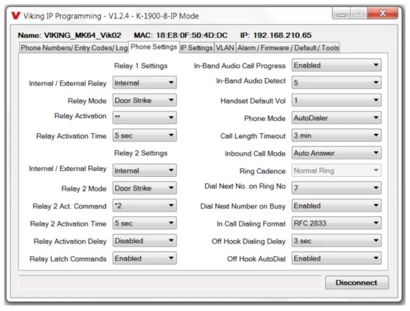
* Note: Latching commands must be enabled in programming.
D. Keyless Entry Codes and One Time Use Keyless Entry Codes
Keyless entry codes may be used by the tenants to provide keyless entry. The K-1900-8-IP Series phone can be programmed with a combination of up to 1000* keyless entry codes or one time use keyless entry codes. The keyless entry codes can be programmed to be from 1 to 6 digits in length. Each keyless entry code can be programmed to activate relay 1 and/or 2 in four different relay modes:
Momentary, Latch, Un-Latch and Toggle. To use a keyless entry code the tenant simply dials “#” followed by the entry code on the K- 1900-8-IP’s keypad. After the one time use keyless entry code has been used, it is instantly cleared from the unit’s memory. This is ideal for issuing keyless entry codes to service personnel, etc.
In the Single and Multi-Number Auto Dialer modes, keyless entry codes can be dialed while the handset is hung up or when the handset is first lifted, when some delay has been programmed for Off Hook Dialing Delay.
E. Proximity Cards
Proximity cards can also be used by the tenants to provide keyless entry. The K-1900-8-IP Series phone can be programmed with up to 1000* proximity card numbers. Each proximity card number can be programmed to activate relay 1 and/or 2 in four different relay modes: Momentary, Latch, Un-Latch and Toggle. To use a proximity card, the tenant simply presents a preprogrammed proximity card within range** of the proximity card reader attached to the K-1900-8-IP Series phone. A short beep will be heard from the card reader indicating a card scan. If the card matches a valid preprogrammed card number the relay will be activated and the visitor can now open the door or gate. Proximity cards can be scanned at anytime, even while a call is in progress.
*Note: 1000 is the total number of Keyless Entry Codes and/or Proximity Card numbers that can be programmed in the Entry Code Database.
**Note: Read range depends on the type of card and card reader being used.
F. 911 Calls
The K-1900-8-IP Series phone is not intended to be an emergency phone and does not try to automatically handle users that dial “911” after picking up the handset. In the Manual Dial Phone mode, the “911” dialed by the user is passed on to the phone system, so it is up to the SIP phone system or provider to route the call properly. In the Single and Multi-Number Auto Dialer modes, a speed dial of “911” can be programmed with primary and rollover phone numbers, to route the calls appropriately. Some delay must be programmed for Off Hook Dialing Delay, to give the user time to dial the “911” before they are automatically routed to another number or hear 3 beeps.
Troubleshooting
If the unit cannot register with the programmed SIP server, three error beeps will be heard in the handset every 30 seconds until communication is restored. This alerts a potential user of a problem with the device that will prevent a phone call from being made. You may silence the error beeps, per instance, by clicking the “Mute Current / Next Alarm” button in the Viking IP Programming Software (see section B on page 8). The error beeps automatically re-enable once the unit is registered, to alert of any new problems that arise.
Using a Viking Model RC-4A for Secure Remote Relay Control
The front panel of the K-1900-8-IP Series phone is mounted using security Torx screws to help prevent intruders from removing the panel and accessing the on board door strike/gate control relays. For applications requiring additional security, a Viking model RC-4A remote relay controller can be used. The relay controller is mounted securely inside the building and connected to the same LAN as the K-1900-8-IP Series phone. The on board door strike relays would not be used in this case as the KK-1900-8-IP Series phone will send an encrypted message to the RC-4A to activate its relays which control the door strikes/gates.
Up to 4 K-1900-8-IP Series phone’s can communicate with one RC-4A allowing you to securely control four entrances.
When using a RC-4A for remote relay control, the K-1900-8-IP Series phone’s relays should be set to “External” in the PC programming. For more information, see DOD 582 at www.VikingElectronics.com.
Related Products
Surface or Pedestal Mount Viking Products While Maintaining Weather and Vandal Resistance
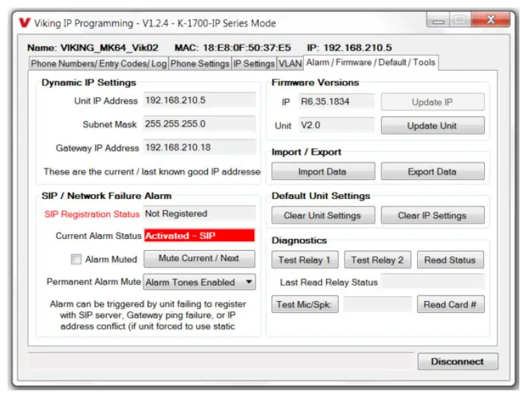
Control Relay Contacts Across a Local Area Network
The RC-4A Network Enabled Relay Controller provides networked control of four relays via an easy-to-use web interface. The same interface can be used to check the status of four contact closure inputs. Relays can be toggled on or off, or user-programmed timed closures can be activated.
The RC-4A can be configured to work as a remote relay for Viking VoIP series entry phones, controlling door strikes and gates when a remote relay is required for security reasons. It can also be programmed to send an email or text message in response to a change in one or more of the sensor inputs. Two RC-4A’s can be set up so that activity on a sensor input of one unit will automatically send a message across the network to activate one of the relays on the other unit. Two levels of user access permit selected users to have full operational and programming rights while others have operational control but not programming capability.
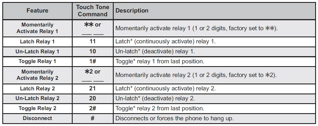
Related Products
125KHz Proximity Card Reader
The model PRX-1 is a 125KHz proximity card reader and is designed to be mounted directly to a metal door or window frame (mullions), making it ideal for applications requiring an access credential. The proximity card reader transmits data in 26-Bit Wiegand format, making it compatible with any of the Wiegand equipped Viking entry controllers.

The PRX-1 delivers non-contact read ranges up to 6 inches (152 mm), and operates from 5 to 14 VDC. Physical size is a compact 3.2 x 1.7 x 0.70 inches (80 x 43 x 17 mm).
Mounting is simplified with horizontal and vertical mounting slots, which allow the reader to be conveniently adjusted and leveled. To allow both indoor and outdoor operation the electronics are sealed in tamper resistant epoxy potting.
Concealing the mounting hardware, the PRX-1 ships with both Black and Ash (Off-White) covers standard. See DOD 221 for more information.
Medium Range 125KHz Proximity Card Reader
The model PRX-3 is a high performance medium range 125KHz proximity card reader. The PRX-3’s compact size yet long read range of up to 16 inches* make it ideal for parking control, gate access, turnstiles, etc. It is designed to be mounted directly to a wall, post, single gang electrical box or use an optional mounting kit for attaching it to a gooseneck pedestal.
Mounting is simplified with horizontal and vertical mounting slots, which allow the reader to be conveniently adjusted and leveled. To increase vandal resistance the chassis is a single piece design with the mounting screws concealed behind a UV stable label.
The proximity card reader transmits data in 26-Bit Wiegand format, making it compatible with any of the Wiegand equipped Viking entry controllers. The PRX-3 is equipped with Enhanced Weather Protection (EWP) for outdoor installations where the unit is exposed to precipitation or condensation. With its sealed connections and fully potted electronics the PRX-3 is designed to meet an IP66 Ingress Protection Rating. For more information see DOD# 228.

125KHz Proximity Cards
The PRX-C and PRX-C-ISO are non-contact security cards that can be presented to the front of a K-1770/75-IP proximity card reader to allow entrance into a secured area. The PRX-C is a clam shell card made made from 0.070” thick plastic to resist bending and folding. A slot is provided at one end to allow a lanyard to be added for creating a “dog tag” style neck strap. The PRX-C-ISO is a thin 0.032” thick flexible “ISO” style proximity card. Much like a credit card,the PRX-C-ISO is perfect for storing in your wallet.
The PRX-FOB is a proximity key ring fob with brass eyelet designed to attach to a key chain or necklace. The PRX-FOB’s compact size is only 1.5” x 1.2” x 0.15” making it one of the smallest available. The cards and fobs are custom pre-programmed. For more information see DOD 198.
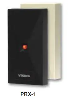
Long Range 4 Channel Transmitters and Receivers
Viking’s model LTR-4 Long Range Wireless 4 Channel Radio Transmitters and LRR-4 Long Range 4 Channel Receivers with integrated receive antenna comprise Vikings high frequency, long-range (RFID) identification solution. Intended for security access control applications, the LRT-4’s wireless communication is based upon a secure, digital, antiplayback routine. The LRT-4
Transmitters have four buttons, each corresponding to its own Wiegand output on the LRR-4 Receiver. Each Transmitter includes an integrated red LED, used to indicate both positive button press and battery strength. They are also equipped standard with a 125KHz HID** compatible potted proximity module allowing the Transmitter to also be used as a close range access credential.
The transmitters and receivers operate at 433-MHz allowing a transmission range of up to 400 ft (line of sight). The LRR-4 receiver has an adjustable read range, optional external antenna connector, terminal block with 4 channel Wiegand data output and a transducer and LED to confirm transmitter button press. The LRR-4 has a conformal coated circuit board mounted in a NEMA 4, 4x rated box for use in outdoor applications. See DOD 226 for more information.
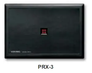
Warranty
IF YOU HAVE A PROBLEM WITH A VIKING PRODUCT, CONTACT: VIKING TECHNICAL SUPPORT AT (715) 386-8666
Our Technical Support Department is available for assistance Monday through Friday 8:00am to 5:00pm central time. So that we can give you better service, before you call please:
1. Know the model number, the serial number and what software version you have (see serial label).
2. Have your Product Manual in front of you.
3. It is best if you are on site.
RETURNING PRODUCT FOR REPAIR
The following procedure is for equipment that needs repair:
- Customer must contact Viking’s Technical Support Department at 715-386-8666 to obtain a Return Authorization (RA) number. The customer MUST have a complete description of the problem, with all pertinent information regarding the defect, such as options set, conditions, symptoms, methods to duplicate problem, frequency of failure, etc.
- Packing: Return equipment in original box or in proper packing so that damage will not occur while in transit. Static sensitive equipment such as a circuit board should be in an anti-static bag, sandwiched between foam and individually boxed. All equipment should be wrapped to avoid packing material lodging in or sticking to the equipment. Include ALL parts of the equipment. C.O.D. or freight collect shipments cannot be accepted. Ship cartons prepaid to: Viking Electronics, 1531 Industrial Street, Hudson, WI 54016
- Return shipping address: Be sure to include your return shipping address inside the box. We cannot ship to a PO Box.
- RA number on carton: In large printing, write the R.A. number on the outside of each carton being returned.
RETURNING PRODUCT FOR EXCHANGE
The following procedure is for equipment that has failed out-of-box (within 10 days of purchase):
- Customer must contact Viking’s Technical Support at 715-386-8666 to determine possible causes for the problem. The customer MUST be able to step through recommended tests for diagnosis.
- If the Technical Support Product Specialist determines that the equipment is defective based on the customer’s input and troubleshooting, a Return Authorization (R.A.) number will be issued. This number is valid for fourteen (14) calendar days from the date of issue.
- After obtaining the R.A. number, return the approved equipment to your distributor, referencing the R.A. number. Your distributor will then replace the Viking product using the same R.A. number.
- The distributor will NOT exchange this product without first obtaining the R.A. number from you. If you haven’t followed the steps listed in 1, 2 and 3, be aware that you will have to pay a restocking charge.
TWO YEAR LIMITED WARRANTY
Viking warrants its products to be free from defects in the workmanship or materials, under normal use and service, for a period of two years from the date of purchase from any authorized Viking distributor. If at any time during the warranty period, the product is deemed defective or malfunctions, return the product to Viking Electronics, Inc., 1531 Industrial Street, Hudson, WI., 54016. Customer must contact Viking’s Technical Support Department at 715-386-8666 to obtain a Return Authorization (R.A.) number.
This warranty does not cover any damage to the product due to lightning, over voltage, under voltage, accident, misuse, abuse, negligence or any damage caused by use of the product by the purchaser or others. This warranty does not cover non-EWP products that have been exposed to wet or corrosive environments. This warranty
does not cover stainless steel surfaces that have not been properly maintained.
NO OTHER WARRANTIES. VIKING MAKES NO WARRANTIES RELATING TO ITS PRODUCTS OTHER THAN AS DESCRIBED ABOVE AND DISCLAIMS ANY EXPRESS OR IMPLIED WARRANTIES OR MERCHANTABILITY OR FITNESS FOR ANY PARTICULAR PURPOSE.
EXCLUSION OF CONSEQUENTIAL DAMAGES. VIKING SHALL NOT, UNDER ANY CIRCUMSTANCES, BE LIABLE TO PURCHASER, OR ANY OTHER PARTY, FOR CONSEQUENTIAL, INCIDENTAL, SPECIAL OR EXEMPLARY DAMAGES ARISING OUT OF OR RELATED TO THE SALE OR USE OF THE PRODUCT SOLD HEREUNDER.
EXCLUSIVE REMEDY AND LIMITATION OF LIABILITY. WHETHER IN AN ACTION BASED ON CONTRACT, TORT (INCLUDING NEGLIGENCE OR STRICT LIABILITY) OR ANY OTHER LEGAL THEORY, ANY LIABILITY OF VIKING SHALL BE LIMITED TO REPAIR OR REPLACEMENT OF THE PRODUCT, OR AT VIKING’S OPTION, REFUND OF THE PURCHASE PRICE AS THE EXCLUSIVE REMEDY AND ANY LIABILITY OF VIKING SHALL BE SO LIMITED.
IT IS EXPRESSLY UNDERSTOOD AND AGREED THAT EACH AND EVERY PROVISION OF THIS AGREEMENT WHICH PROVIDES FOR DISCLAIMER OF WARRANTIES, EXCLUSION OF CONSEQUENTIAL DAMAGES, AND EXCLUSIVE REMEDY AND LIMITATION OF LIABILITY, ARE SEVERABLE FROM ANY OTHER PROVISION AND EACH PROVISION IS A SEPARABLE AND INDEPENDENT ELEMENT OF RISK ALLOCATION AND IS INTENDED TO BE ENFORCED AS SUCH.
If trouble is experienced with the K-1900-8-IP phone, for repair or warranty information, please contact:
Viking Electronics, Inc., 1531 Industrial Street, Hudson, WI 54016 (715) 386-8666
WHEN PROGRAMMING EMERGENCY NUMBERS AND (OR) MAKING TEST CALLS TO
EMERGENCY NUMBERS:
Remain on the line and briefly explain to the dispatcher the reason for the call. Perform such tests in off-peak hours, such as early morning or late evenings.
PART 15 LIMITATIONS
This equipment has been tested and found to comply with the limits for a Class A digital device, pursuant to Part 15 of the FCC Rules. These limits are designed to provide reasonable protection against harmful interference when the equipment is operated in a commercial environment. This equipment generates, uses, and can radiate radio frequency energy and, if not installed and used in accordance with the instruction manual, may cause harmful interference to radio communications. Operation of this equipment in a residential area is likely to cause harmful interference in which case the user will be required to correct the interference at his own expense.
CANADA
This class A digital apparatus complies with Canadian ICES-003. Cet appareil numerique de la classe A est conforme a la norme NMB-003 du Canada Product Support: 715-386-8666
Due to the dynamic nature of the product design, the information contained in this document is subject to change without notice. Viking Electronics, and its affiliates and/or subsidiaries assume no responsibility for errors and omissions contained in this information. Revisions of this document or new editions of it may be issued to incorporate such changes.
]]>
The K-1900-8 Series panel phone can either auto-dial a phone number each time the handset is lifted, be used as a multi-number auto-dialer, or be used as a standard (dumb) phone. The unit will touch tone or pulse dial and will not auto-dial on incoming calls.
The K-1900-8 Series housing consists of a heavy gauge stainless steel panel, metal touch tone keypad, armored cable, heavy duty handset, and all metal cradle. The K-1900-8 Series can be easily touch tone programmed at the shop or installation site. All programming is stored in non-volatile memory.
The K-1900-812L and K-1900-812L-EWP feature a 12″ long armored cable with an internal stainless steel lanyard for additional cable strength.
The K-1900-8-EWP and K-1900-812L-EWP share all the features of the K-1900-8 and K-1900-812L in addition to Enhanced Weather Protection (EWP) for outdoor installations where the unit is exposed to precipitation or condensation. EWP products are designed to meet IP66 standards and may feature foam rubber gaskets, sealed connections, gel-filled butt connectors, as well as potted circuit boards with internally sealed, field-adjustable trim pots and DIP switches for easy on-site programming. For more information on EWP, see DOD 859.
Note: If a ringer is required, use an external unit such as the Viking SR-1 (DOD 477), or LPR-1 (DOD 550).
Features
- Vandal Resistant Features: 12 gauge (0.105″ thick) 316 stainless steel panel with permanent laser etched graphics, armored cable, metal cradle, heavy-duty metal keypad, and hex drive mounting screws
- Weather Resistant Features: Marine grade 316 stainless steel faceplate and screws, and internally sealed keypad
- Auto dials one programmable speed dial number (up to 32 digits)
- Multi-number dialer mode adds 5 speed dial numbers (up to 16 digits)
- Touch tone or pulse dialing
- Non-volatile memory (no batteries required)
- Operates on analog PABX and key system extensions or analog Centrex and CO lines
- Programmable 6 digit security code
- Touch tone programmable
- Optional Enhanced Weather Protection (EWP) available – EWP products are designed to meet IP66 Ingress Protection Rating, see DOD 859
- 12″ armored handset cable on K-1900-812L and K-1900-812L-EWP
- 36″ armored handset cable on K-1900-8 · 54″ armored handset cable on K-1900-8-EWP
- Programmable pre-dial pause
- Blocks fraudulent calls from hand held pocket dialers
- Limited toll Restriction in dumb phone mode
- Hearing aid compatible amplified handset with sealed push button volume control
- Programmable default volume level
- Programmable volume control disable
- Flush mount with included steel rough-in box, or use an optional VE-5×10 surface mount box (not included, see DOD 424)
www.VikingElectronics.com
Information: 715-386-8861
Applications
- Catalog sales
- Kiosks
- Courtesy and customer service phones
- Automated tellers (ATM’s)
- Hot-line reservation phones
- Security and emergency phones
- Replaces leased ringdown circuits
- Gate/entrance communication in noisy locations (diesel trucks, factory noise, etc.)
Specifications
Power: Telephone line powered (20V DC/18mA minimum)
Dimensions for Standard Model
Phone : 5.0″ x 10.0″ x 4.54″ (127mm x 254mm x 113mm)
With rough-in box: 5.0″ x 10.0″ x 5.53″ (127mm x 254mm x 141mm)
Dimensions for EWP Model
Phone: 5.0″ x 10.0″ x 4.93″ (127mm x 254mm x 125mm)
With rough-in box: 5.0″ x 10.0″ x 5.61″ (127mm x 254mm x 143mm)
Shipping Weight: 5 lbs (2.3 kg )
Operating Temperature: -30°F to 140°F (-34°C to 60°C)
Humidity – Standard Model: 5% to 95% non-condensing
Humidity – EWP Model : Up to 100% condensing
K-1900-812L(EWP) Handset Cable Length: 12″ to 12.7″ (31 cm to 33 cm)
K-1900-8 Handset Cable Length: 34″ to 37″ (86 cm to 94 cm)
K-1900-8-EWP Handset Cable Length: 52″ to 57″ (132 cm to 145 cm)
Touch Tone Dial Speed: Normal = 120ms on/off, Fast = 50ms on/off
Pulse Dial Speed: Normal = 10 pps, Fast = 20 pps
Connections: (2) gel-filled butt connectors
Installation
To install the K-1900-8 panel phone, attach the panel using the provided screws or use the optional VE-5×10 weather resistant surface mount box. Note: Four extra screws and nuts are provided to fill the unused mounting holes. The optional VE-5×10 surface mount box (shown below) is designed to be surface mounted to a wall, post, single gang box or a VE-GNP or VE-GNP-2 goose neck pedestal (shown right). The K-1900-8 can also be mounted in an optional VE-9×20 Weatherproof Enclosure (DOD 413). Note: When mounting a K-1900-8-EWP in a VE-9×20, the length of the handset cable must be reduced. Use a 3/32″ hex key or bit to loosen the set screw in the brass handset cable retainer. Pull approximately 18 inches of the cable through the panel and retighten the set screw.
IMPORTANT: Electronic devices are susceptible to lightning and power station electrical surges from both the AC outlet and the telephone line. It is recommended that a surge protector be installed to protect against such surges.
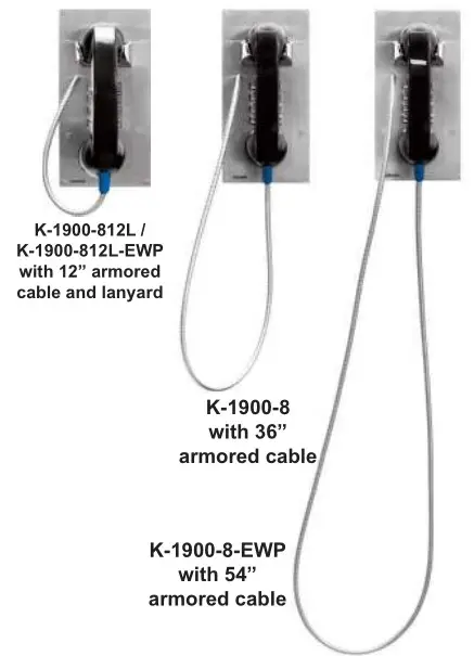
Programming
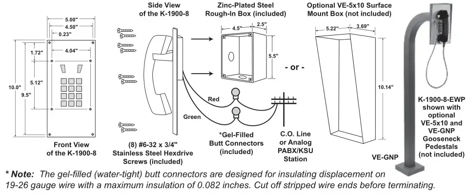
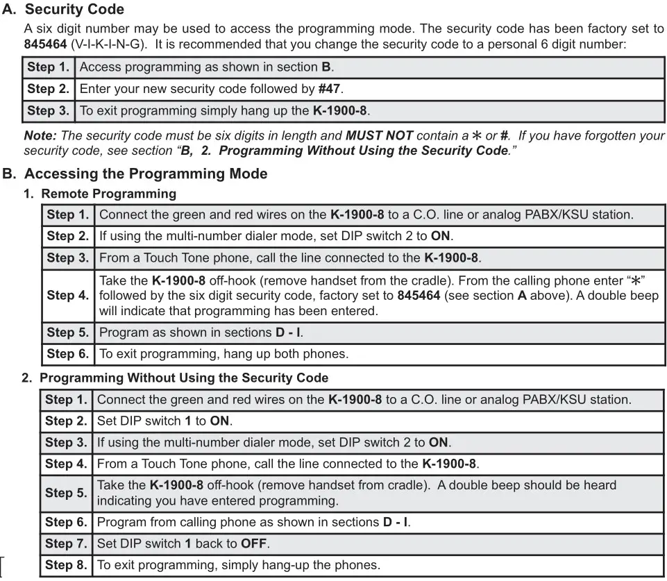
Operation
A. Single Number Auto Dialer
In the single number auto dialer mode (see Programming section D), when the K-1900-8 is taken off-hook it will speed dial the phone number programmed in memory location #00. After speed dialing is complete, the keypad is available for user Touch Tone signaling. In this mode, the K-1900-8 can be programmed to block hand held dialers (see Programming section F).
B. Standard (Dumb) Phone Mode
If nothing is programmed in memory locations #00, the K-1900-8 drops into the dumb phone mode. The phone will act like any standard 2500 type telephone. The only feature which may be enabled is the limited toll restriction (see Programming section I).
C. Multi-Number Auto Dialer
In the multi-number auto dialer mode (see Programming section D), when the K-1900-8 is taken off-hook it will dial one of six speed dial numbers programmed in memory locations #01, #02, #03, #04, #05 and #00 when the user presses 1, 2, 3, 4, 5, or 0 (respectively) on the keypad. After speed dialing is complete, the keypad is available for user Touch Tone signaling. In this mode, the K-1900-8 can be programmed to block hand held pocket dialers (see Programming section F).
D. Handset Receiver Volume Adjustment
The K-1900-8 has a sealed push button switch located on the inside handle of the handset. Each push of the button will rotate through the receiver volume levels if enabled. After four actuations, the receiver volume is back to its default setting. Hanging up the phone will automatically set the receiver volume to its default setting.
Warranty
IF YOU HAVE A PROBLEM WITH A VIKING PRODUCT, CONTACT: VIKING TECHNICAL SUPPORT AT 715-386-8666
Our Technical Support Department is available for assistance Monday through Friday 8am – 5pm central time. So that we can give you better service, before you call please:
- Know the model number, the serial number and what software version you have (see serial label).
- Have your Product Manual in front of you.
- It is best if you are on site.
RETURNING PRODUCT FOR REPAIR
The following procedure is for equipment that needs repair:
- Customer must contact Viking’s Technical Support Department at 715-386-8666 to obtain a Return Authorization (RA) number. The customer MUST have a complete description of the problem, with all pertinent information regarding the defect, such as options set, conditions, symptoms, methods to duplicate problem, frequency of failure, etc.
- Packing: Return equipment in original box or in proper packing so that damage will not occur while in transit. Static sensitive equipment such as a circuit board should be in an anti-static bag, sandwiched between foam and individually boxed. All equipment should be wrapped to avoid packing material lodging in or sticking to the equipment. Include ALL parts of the equipment. C.O.D. or freight collect shipments cannot be accepted. Ship cartons prepaid to: Viking Electronics, 1531 Industrial Street, Hudson, WI 54016
- Return shipping address: Be sure to include your return shipping address inside the box. We cannot ship to a PO Box.
- RA number on carton: In large printing, write the R.A. number on the outside of each carton being returned.
RETURNING PRODUCT FOR EXCHANGE
The following procedure is for equipment that has failed out-of-box (within 10 days of purchase):
- Customer must contact Viking’s Technical Support at 715-386-8666 to determine possible causes for the problem. The customer MUST be able to step through recommended tests for diagnosis.
- If the Technical Support Product Specialist determines that the equipment is defective based on the customer’s input and troubleshooting, a Return Authorization (R.A.) number will be issued. This number is valid for fourteen (14) calendar days from the date of issue.
- After obtaining the R.A. number, return the approved equipment to your distributor, referencing the R.A. number. Your distributor will then replace the Viking product using the same R.A. number.
- The distributor will NOT exchange this product without first obtaining the R.A. number from you. If you haven’t followed the steps listed in 1, 2 and 3, be aware that you will have to pay a restocking charge.
TWO YEAR LIMITED WARRANTY
Viking warrants its products to be free from defects in the workmanship or materials, under normal use and service, for a period of two years from the date of purchase from any authorized Viking distributor. If at any time during the warranty period, the product is deemed defective or malfunctions, return the product to Viking Electronics, Inc., 1531 Industrial Street, Hudson, WI., 54016. Customer must contact Viking’s Technical Support Department at 715-386-8666 to obtain a Return Authorization (R.A.) number.
This warranty does not cover any damage to the product due to lightning, over voltage, under voltage, accident, misuse, abuse, negligence or any damage caused by use of the product by the purchaser or others. This warranty does not cover non-EWP products that have been exposed to wet or corrosive environments. This warranty does not cover stainless steel surfaces that have not been properly maintained.
NO OTHER WARRANTIES. VIKING MAKES NO WARRANTIES RELATING TO ITS PRODUCTS OTHER THAN AS DESCRIBED ABOVE AND DISCLAIMS ANY EXPRESS OR IMPLIED WARRANTIES OR MERCHANTABILITY OR FITNESS FOR ANY PARTICULAR PURPOSE.
EXCLUSION OF CONSEQUENTIAL DAMAGES. VIKING SHALL NOT, UNDER ANY CIRCUMSTANCES, BE LIABLE TO PURCHASER, OR ANY OTHER PARTY, FOR CONSEQUENTIAL, INCIDENTAL, SPECIAL OR EXEMPLARY DAMAGES ARISING OUT OF OR RELATED TO THE SALE OR USE OF THE PRODUCT SOLD HEREUNDER.
EXCLUSIVE REMEDY AND LIMITATION OF LIABILITY. WHETHER IN AN ACTION BASED ON CONTRACT, TORT (INCLUDING NEGLIGENCE OR STRICT LIABILITY) OR ANY OTHER LEGAL THEORY, ANY LIABILITY OF VIKING SHALL BE LIMITED TO REPAIR OR REPLACEMENT OF THE PRODUCT, OR AT VIKING’S OPTION, REFUND OF THE PURCHASE PRICE AS THE EXCLUSIVE REMEDY AND ANY LIABILITY OF VIKING SHALL BE SO LIMITED.
IT IS EXPRESSLY UNDERSTOOD AND AGREED THAT EACH AND EVERY PROVISION OF THIS AGREEMENT WHICH PROVIDES FOR DISCLAIMER OF WARRANTIES, EXCLUSION OF CONSEQUENTIAL DAMAGES, AND EXCLUSIVE REMEDY AND LIMITATION OF LIABILITY, ARE SEVERABLE FROM ANY OTHER PROVISION AND EACH PROVISION IS A SEPARABLE AND INDEPENDENT ELEMENT OF RISK ALLOCATION AND IS INTENDED TO BE ENFORCED AS SUCH.
FCC REQUIREMENTS
This equipment complies with Part 68 of the FCC rules and the requirements adopted by the ACTA. On the side of this equipment is a label that contains, among other information, a product identifier in the format US:AAAEQ##TXXXX. If requested, this number must be provided to the telephone company.
The REN is used to determine the number of devices that may be connected to a telephone line. Excessive REN’s on a telephone line may result in the devices not ringing in response to an incoming call. In most but not all areas, the sum of the REN’s should not exceed five (5.0) To be certain of the number of devices that may be connected to a line, as determined by the total REN’s, contact the local telephone company. For products approved after July 23, 2001, the REN for this product is part of the product identifier that has the format US:AAAEQ##TXXXX. The digits represented by ## are the REN without a decimal point (e.g., 03 is a REN of 0.3). For earlier products, the REN is separately shown on the label.
The plug used to connect this equipment to the premises wiring and telephone network must comply with the applicable FCC Part 68 rules and requirements adopted by the ACTA. If your home has specially wired alarm equipment connected to the telephone line, ensure the installation of this K1900-8 does not disable your alarm equipment. If you have questions about what will disable alarm equipment, consult your telephone company or a qualified installer.
If the K-1900-8 causes harm to the telephone network, the telephone company will notify you in advance that temporary discontinuance of service may be required. But if advance notice isn’t practical, the telephone company will notify the customer as soon as possible. Also, you will be advised of your right to file a complaint with the FCC if you believe it is necessary.
The telephone company may make changes in its facilities, equipment, operations, or procedures that could affect the operation of the equipment. If this happens, the telephone company will provide advance notice in order for you to make the necessary modifications to maintain uninterrupted service.
If trouble is experienced with the K-1900-8, for repair or warranty information, please contact:
Viking Electronics, Inc., 1531 Industrial Street, Hudson, WI 54016 715-386-8666
If the equipment is causing harm to the telephone network, the telephone company may request that you disconnect the equipment until the problem is resolved.
Connection to Party Line Service is subject to State Tariffs. Contact the state public utility commission, public service commission or corporation commission for information.
WHEN PROGRAMMING EMERGENCY NUMBERS AND (OR) MAKING TEST CALLS TO EMERGENCY NUMBERS:
Remain on the line and briefly explain to the dispatcher the reason for the call. Perform such activities in the off-peak hours, such as early morning or late evenings.
It is recommended that the customer install an AC surge arrester in the AC outlet to which this device is connected. This is to avoid damaging the equipment caused by local lightning strikes and other electrical surges.
PART 15 LIMITATIONS
This equipment has been tested and found to comply with the limits for a Class A digital device, pursuant to Part 15 of the FCC Rules. These limits are designed to provide reasonable protection against harmful interference when the equipment is operated in a commercial environment. This equipment generates, uses, and can radiate radio frequency energy and, if not installed and used in accordance with the instruction manual, may cause harmful interference to radio communications. Operation of this equipment in a residential area is likely to cause harmful interference in which case the user will be required to correct the interference at his own expense.
Due to the dynamic nature of the product design, the information contained in this document is subject to change without notice. Viking Electronics, and its affiliates and/or subsidiaries assume no responsibility for errors and omissions contained in this information. Revisions of this document or new editions of it may be issued to incorporate such changes.
4 DOD 362
Printed in the U.S.A.
ZF301770 Rev F
]]>