![]() 4931 N 300 W Provo, UT 84604
4931 N 300 W Provo, UT 84604
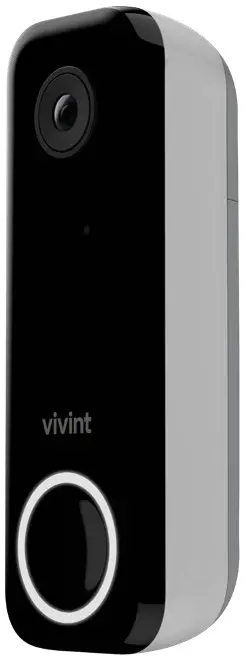
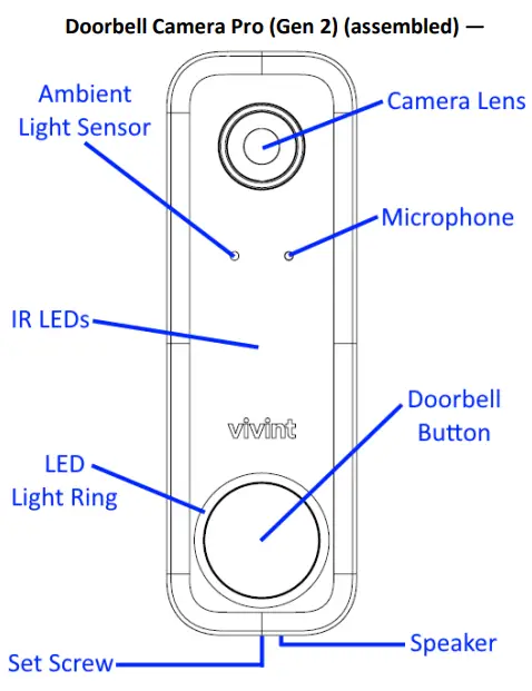
Vivint Doorbell Camera Pro (Gen 2)
(VS-DBC350-WHT)
Quick Reference (User Manual — Installation & Operation)
PRINT INSTRUCTIONS:
REFERENCE SHEET FOR VS-DBC350-WHT P/N 77-600041-001 REV 1.0 |
INK: BLACK | MATERIAL: 20 LB MEAD BOND | SIZE: 8.50″ X 11.00″ SCALE 1:1 |
FOLDS: BI-FOLD VERTICAL, BI-FOLD HORIZONTAL (TO FIT IN BOX)

The Vivint Doorbell Camera Pro (Gen 2) can be added to an integrated Vivint Smart Home system, letting the homeowner know whenever a visitor comes to their door, whether that person presses the doorbell button or not, via smart notifications. With the doorbell camera, you can see and speak with the visitor (whether you are inside the home or away) via the control panel and mobile apps. The doorbell camera provides life and recorded video that can be viewed at the control panel as well as remotely via the apps; a speaker and microphone array for audio/communication capabilities including two-way talk via the panel or apps; and an LED light ring on the doorbell button that indicates real-time camera function and status.
Professionally installed by a Vivint technician, the doorbell camera is added to the panel network either via NFC, Wi-Fi Connect, or WPS. Once connected to the system, the doorbell camera can be used in conjunction with other smart home automation devices and features, such as remote door locks, garage door controllers, and light switches. Other features include Night vision with IR LEDs; Full 180° FOV (field of view); Pinch-to-zoom video image; Person-triggered and/or ring notifications; Micro SD card support for on-device 24/7 playback DVR.
This document includes a product description, installation and tests instructions, basic operation/user functionality overview, as well as technical specifications and regulatory compliance notices and declarations.
Installation Instructions
Installing the doorbell camera initially requires some different steps depending on whether or not there is an existing doorbell, but once the power source is set up the procedure is essentially the same. The Vivint technician should carefully read all of these installation steps (and tips) in order to ensure a successful installation and optimal performance. For additional information, refer to the Field Service Smart Home Pros website.
Scenario 1: IF there is an existing doorbell: a) Locate the chime box and remove the FRT and TRANS wires from the screw terminals keeping the wires separated, b) Verify the doorbell no longer has power, and c) Detach the doorbell.
(NOTE: If there is a wire on the REAR terminal for a working doorbell, remove it and cap it off. Also, if there are multiple chime boxes, you need to locate them and remove their FRT and TRANS wires.)
Next, follow these steps to pair and install the camera, and add it to the system:
- First, pair the doorbell camera to the panel via NFC. At the panel, tap on the menu icon (…) in the bottom right corner > tap Software version > enter the PIN code 2203 > tap Smart Home devices > Cameras > and then tap Add camera.
- Tap NFC > and then tap Add. Align the logo on the front of the DBC with the white light on the panel, and hold it until the pairing is complete.
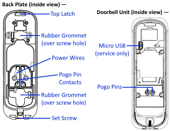
- Mount the camera. Run the power wires through the back plate’s rubber grommet, and then strip and secure each wire to a screw terminal. Polarity does not matter.
- Attach the back plate to the wall/doorframe with two screws. Secure the rubber gaskets.
- If applicable, at the chime box, twist and cap the FRT and TRANS wires together.
- Place the doorbell unit on the back plate, by first attaching the bottom on to the set screw, and then swinging it up so that it clips securely into the top latch.
- Verify power is present at the DBC. The LED light will illuminate. (See LED descriptions)
- Once the doorbell camera has finished booting (wait a few minutes), it will show online.
IMPORTANT: This process should NOT be interrupted and could take several minutes in order to load firmware and configure settings. - Verify that you can view live video at the panel screen and with the app.
INSTALLATION TIPS / BEST PRACTICES:
- Push any excess wire back into the wall. No exposed wires. No exterior wire runs.
- If the camera view is blocked, use a spacer to adjust the angle.
- On brick/concrete/stucco/wood/vinyl: Use outdoor-rated screws only. Pre-drill if necessary.
- Do NOT use drywall screws (or any screws that won’t sit flush on the back plate).
- Do NOT mount to metal surfaces.
- NOTE: Refer to the Field Service website for detailed guidelines on replacing an existing doorbell when the power source voltage is not within the 12-24V range.
Operation Overview / User Functionality
Once the doorbell camera is up and running, the user can perform the following functions — similar to other Vivint-connected cameras — at the panel and via the apps. For detailed instructions, refer the homeowner to the online Help resources (articles and video tutorials) at the Vivint Support site.
- View a live video feed
- View recorded video clips
- Receive person-triggered (event) notifications
- Engage in two-way talk
For camera management and configuration, at the Devices > Cameras settings page, the user can: - Adjust detection and video settings (app only)
- Reboot the camera
- Delete the camera
Technical / Hardware Specifications
| Vivint Part Number (P/N) | VS-DBC350-WHT |
| Model Number (M/N) | CM06 |
| Color | White |
| Weight | 9.1 oz. (approximate, includes camera and back plate) |
| Dimensions | 133.5 x 43.5 x 37 mm (5.3 x 1.7 x 1.5 in) |
| Power Usage | 14-24V AC 1.0A min.; 12-24V DC 1.0A min. |
| Backup Battery | None |
| Connectivity | Wi-Fi 6 2.4GHz/5GHz; 802.11 b/g/n/ax; 2×2 MU-MIMO; Bluetooth/BT Low Energy (BLE) 5.0; NFC tag at 13.56 MHz |
| Camera Lens | 5-megapixel sensor |
| Video Max Resolution | 1664p 1:1 |
| FOV | Full 180° field of view |
| Night Vision | High-powered IR LEDs (850nm) |
| Micro SD Card | 64GB micro SD card for onboard DVR support (local storage) |
| Audio | Built-in speaker and microphone array |
| Environmental Temperature | -4°F to 113°F (-20°C to 45°C) |
| Weatherproofing | Yes (IP33, with UV protection) |
What the LED Colors Mean
The camera doorbell button is highlighted by an LED light ring that displays different colors in order to indicate various functions and status, as described below.
- Yellow (Breathing) — Booting up
- Green (Breathing) — AP mode, ready to pair/connect
- Green (Blinking) — WPS connection in progress (config.)
- Green (Fast Blinking) — WPS connection success
- Red (Solid) — WPS connection failure
- White (Solid) — Camera online
- Blue (Solid) — Two-way talk
- Blue (Blinking) — Updating firmware
- Red & Green (Blinking) — Factory reset (press and hold)
Troubleshooting Tips
Possible failures with the doorbell camera and what to do in order to resolve:
- DBC is not adding (learning in) –
✓ Power cycle the DBC
✓ Reset the panel network module
✓ Reboot the panel - DBC is offline –
✓ Verify the DBC is receiving power
✓ Verify the DBC is securely attached
✓ Reset the doorbell camera - Doorbell is not ringing –
✓ Check the volume at the panel
✓ Verify the doorbell chime is enabled
✓ Power cycle the DBC (and the panel next) - Two-way talk is not working –
✓ Make sure the button is being pressed when talking
✓ Verify the network upload speed is sufficient
✓ Power cycle the DBC (and the panel next)
Wireless Product Notice
Wireless communications hardware provides reliable communication; however, there are some limitations that must be observed.
- The transmitters are required to comply with all applicable wireless rules and regulations. As such, they have limited transmitter power and limited range.
- Wireless signals may be blocked by radio signals that occur on or near the wireless operating frequencies.
FCC and ISED Canada Regulatory Compliance Declarations*
CAUTION! Unauthorized changes or modifications could void the user’s authority to operate the equipment.
This device has been tested and found to comply with the limits for a Class B digital device, pursuant to Part 15 of FCC Rules, and Industry Canada license-exempt RSS standard(s). Operation is subject to the following two conditions:|
(1) This device may not cause harmful interference, and
(2) This device must accept any interference received, including interference that may cause undesired operation of the device.
These limits are designed to provide reasonable protection against harmful interference in a residential installation. This equipment generates, uses, and can radiate radio frequency energy and, if not installed and used in accordance with the instructions, may cause harmful interference to radio communications. However, there is no guarantee that interference will not occur in a particular installation. If this equipment does cause harmful interference to radio or television reception, which can be determined by turning the equipment off and on, the user is encouraged to try to correct the interference by one or more of the following measures: Reorient or relocate the receiving antenna; Increase the separation between the equipment and the receiver; Connect the equipment into an outlet on a circuit different from that to which the receiver is connected; Consult the dealer or an experienced radio/television technician for help.
- This product complies with FCC and IC RSS-102 radiation exposure limits for an uncontrolled environment. Avoid operating this product at a distance less than 7.9 in (20 cm) from the user.
- The transmitter module may not be co-located with any other transmitter or antenna.
- For products available in the USA/Canada market, only channel 1~11 can be operated. Selection of other channels is not possible.
FCC ID: 2AAAS-CM06
IC: 10941A-CM06
*For complete regulatory compliance information, go to: vivint.com/fcc
© 2022 Vivint Inc. All Rights Reserved.
www.vivint.com
1-800-216-5232
Device M/N: CM06
Doc P/N: 77-600041-001 Rev. 1.0