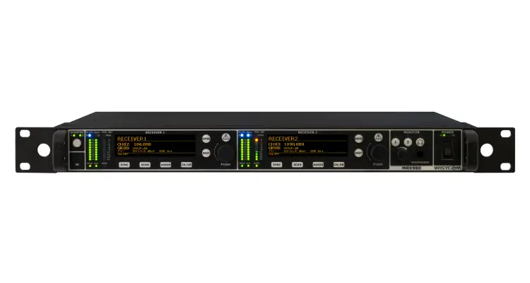
ULTRA-WIDEBAND TRUE DIVERSITY DUAL RECEIVER
rev.08 (ref. FW 1.11)
Date: 17 January 2020
GENERAL DESCRIPTION
Wisycom MRK980 is a true diversity, ultra-wideband dual channel receiver. With its 1090MHz tuning range, it ensures the users have exceptional flexibility, combined with superb selectivity and inter-modulation immunity, for best operating performances of the wireless microphone systems.
MRK980 also features an internal DSP processor, Wisycom famous Multicompanding system, new Dante compatibility and a completely renewed user interface, which makes this system easy and quick to setup.
The MRK980 is designed to be:
- “Easy & quick to use” thanks to automatic setup functions (i.e. frequencies, squelch), remote configuration utilities (Dante/Ethernet control connections), a display with intuitive contextual menu navigation and shortcut buttons on the front panel.
- “Extremely flexible”, with an incredible frequency agility of 1090MHz (VHF/UHF/DME); more than one rack can be connected together through a simple ethernet cable to act as a multi-channel receiver. Moreover the DSP board allows the units to work with several digital audio outputs (i.e. AES/EBU, DANTE, …), with multi-companding compatibilities and the new adaptive squelch function.
- “Best in class performance”, thanks to the latest Wisycom technology, the unit has extreme RF sensitivity and immunity plus superb audio quality.
- “A durable & upgradable investment”, thanks to the very robust design (aluminum housing) and the ability to upgrade/enhance the unit performances with a simple slot in card (pc-like through the DEXB expansion bus)
MRK980 system is already set up for the unique PTT function (remote command), developed and patented by Wisycom:
Simply pushing this button (PTT), the presenter initiates remote switching of the receiver’s output, from the “main line” to the additional “intercom line”, in order to be able to talk “off-air” directly with the technical team. Then all the PTT MICs can be connected in pre-fad creating a clever intercom setup.
MAIN FEATURES
- High immunity in a strong RF environment
- Incredible switching bandwidth
- Top class audio performances and flexibility thanks to the digital processors
- High reliability and durability
- Two channels True Diversity receiver (full DSP processing)
- Up to 1090 MHz bandwidth in the 170/1260 MHz range
- Push to talk (PTT) enabled with dedicated outputs
- Analogue, AES/EBU & Dante outputs (with redundancy)
- Dante™ machine Synchronized mode
- Next Gen Multiband front-end filtering:
- High Q moving filter 170-230 MHz
- High Q moving filter 470-800 MHz
- High Q moving filter 960-1160 MHz (DME) (or 806-810 MHz SAW filter for Japan)
- Country specific SAW filters: USA 940-960 MHz or Japan 1240-1260 MHz
- Wideband and Narrowband DSP-FM operation (SW selectable):
- Narrowband allows 50% more spectrum efficiency (200/250 kHz channel density)
- Narrowband allows about 3dB extra sensitivity and noise immunity
- Extreme low noise VCO with ultra-fast spectrum scan for optimal quick & easy setup
- High contrast OLED display
- Monitor & control through USB and Wisycom Manager 2.0 (computer SW)
- Expansion slot for GPIO or future additional features
TECHNICAL DESCRIPTION
The MRK980 is a professional dual diversity receiver for wireless microphone reception especially designed for broadcast production, live stages, theatres and top professional applications.
One of the milestones in the design of the MRK980 is high reliability as most of the circuit blocks in the receiver are completely independent from another.
Below you can see the schematic with an overview of main receiver functions.
Starting from the antenna inputs, each antenna can be independently powered from a single power regulator monitored by the microcontroller.
For each antenna the RF signal is split to feed receiver 1 and 2 with a wide-band splitter. This way any of the two receivers can be tuned to any frequency within the tuning range, e.g. you can have receiver 1 in VHF and receiver 2 in DME band.
Receiver 1 and 2 are true diversity receivers: each one consists of two receivers tuned to the same frequency, hereafter called section A and section B. The receiver 1 section A and the receiver 2 section A are connected to the antenna A, the receiver 1 section B and the receiver 2 section B are connected at the antenna B.

Each receiver has its own demodulated signal and its own RSSI signal (Received Signal Strength Indication); a microcontroller selects or combines signals from section A & B to have the best audio. The demodulated signal is then sent to the digital audio processor.
The data subcarrier is digitally filtered with a highly selective filter (bandwidth 3Hz). Each filter has its own data demodulator, one for medium speed data detection at the output of the first filter and one at low speed data detection at the output of the second filter. Both of the demodulators are connected to the supervisory micro controller for data detection and signaling.
Digital audio processors (one for each receiver): the demodulated signal is filtered by a low pass anti-aliasing filter and then converted into the digital domain with a 96KHz/24bit audio A/D converter. The digital signal processor (DSP), working in double precision, replicates all the analog functions with very high accuracy, ultra-low distortion and without the typical analog problems such as components tolerances or temperature drifts etc. The highspeed audio algorithms maintains the audio delay at about 0.37 milliseconds, making it ideally suited to live events and to keep audio delay as short as possible. The DSP unit also filters and demodulates the data carrier and communicates all the parameters and information to the supervisory micro controller. The audio output goes to the digital outputs (AES3) or is converted in the analog domain with a high quality 24 bits 96KHz D/A converter and an anti-aliasing filter.
The analogue audio signal is routed in three parallel ways, LINE, AUX and HEADPHONE MONITOR amplifier.
The headphone monitor amplifier is controlled by the buttons on the front panel and by the volume knob. The monitor output depends on the squelch and on the tone squelch only in the TSQ ON selection. In TSQ OFF and in TSQ ADV the monitor output is muted only by the squelch control.
The two analogue audio ways, LINE and COM, have the same audio quality and are controlled by the “Tone squelch matrix”. Each audio driver has a VCA for the soft switching of the audio signal and the muting functions, controlled by the supervisory microcontroller. After the VCA, an electronically balanced amplifier drives the output signal, directly or thru a very low impedance screened audio transformer (optional). The audio output without transformer can withstand up to +52 Vdc of phantom supply with no damage and up to 100V with transformer.
USER GUIDE
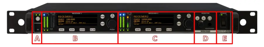
FRONT PANEL
MRK980 allows an easy and quick configuration using buttons, push knobs and displays. The front panel is functionally divided in the following section:
A – ANTENNA BOOSTER and INFRARED PORT: ON/OFF booster button for A&B antennas and IRDA port.
B – RECEIVER 1 CONFIGURATION: display, menu and shortcut buttons.
C – RECEIVER 2 CONFIGURATION: display, menu and shortcut buttons.
D – MONITORING AREA: monitoring audio output on headphone jack (6.3mm – ¼”)
E – RECEIVER POWER SWITCH: turn the receiver ON/OFF.NOTE: the devices takes 5 secs to turn OFF for safety reasons (e.g. accidental turn OFF)
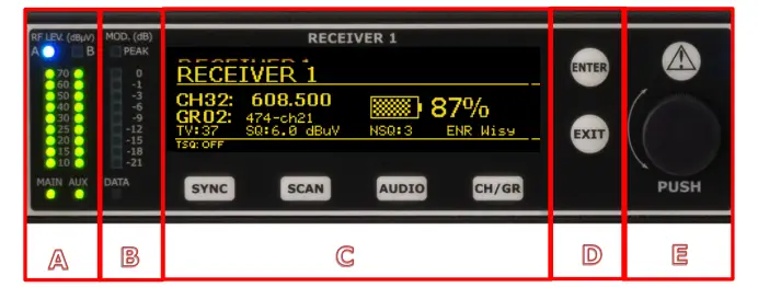
RECEIVER 1 and RECEIVER 2
AREA A: RF Bars, MAIN and AUX LED indicates what output port is currently in use.
AREA B: Modulation bar and DATA led which indicates the Ethernet connection status (ON/OFF)
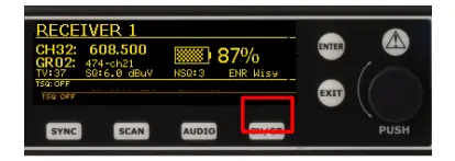
AREA C: Receiver display (Name, channel info, audio info, sub menu) and shortcuts buttons (SYNC, SCAN, AUDIO, CH/GR) to quickly access the main receiver functions.
AREA D: action button to choose or exit while in the menu.
AREA E: rotary knob to scroll within the menu and choose different options (push) and lamp indicator.
- Fixed Yellow (Warning): no audio on both COM and AUX outputs
- Red slow blinking (Alarm level 1): Tx battery level <25%
- Red fast blinking (Alarm level 2): Tx battery level <12%
- Red fixed (Alarm level 3): A or B antenna short circuit (pop up on the display will also shows up “Overcurrent on antenna A/B”)
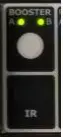
ANTENNAS BOOSTER
BOOSTER activates antenna power (phantom power) with 12VDC (200mA max) and the green LED is illuminated. Blinking LED indicates a fault condition. If this is the case, power down the device and check for short circuits or overloads on the RF cables or the boosters.
Booster supply for antenna A and antenna B are independent, switchable from the RADIO > OPTIONS menu.
MONITOR & POWER
Monitor 1 and 2 buttons activate monitor audio on the jack output (6.3mm – ¼”), 1 and 2 respectively per receiver (a green LED is lighted when audio is enabled). Audio level can be adjusted with the rotary knob. The red LED (CLIP) indicates a clipping in the audio monitor output. The button labelled ‘headphones’ enables the advanced monitoring options (e.g. Dante monitoring) configurable by the Audio or the Dante sub menus.
Power ON/OFF powering switch turns on/off the receiver. When in OFF position both phases are disconnected from power. Note that to avoid unintentional shutdowns, the device takes 5 seconds to turn off. During those 5 seconds (countdown on the display) the device is still working and the switching off procedure can be interrupted by switching the MRK980 back on before the 5 seconds countdown expires.
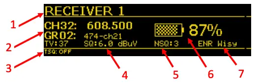
LCD DISPLAY: MAIN VIEW

All the basic information about the receiver status can be found in the main menu overview. Here you can find the following info:
- Receiver name
- Current tuned frequency, Group, Channel and TV Channel
- Tone Squelch Status (ON/OFF)
- Squelch Level
- Noise Squelch Level
- Transmitter Battery status
- Compander currently in use
Through the main menu on the LCD display and the LED bars for the RF level and modulation the user has real time monitoring off the wireless channel in use.
REAR PANEL
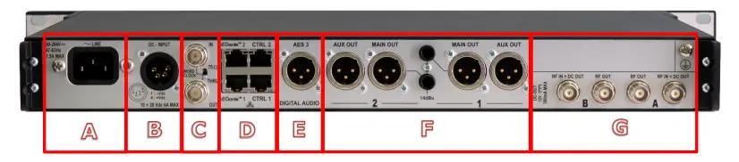
The rear panel is functionally divided into the following sections:
A – Main Power Supply
B – Redundant +12V DC Power Supply
C – Word Clock I/O
D – Remote control module: redundant Dante connectors and redundant Ethernet connectors
E – AES3 Digital output
F – Receiver 1 and Receiver 2 Audio outputs: Main, Aux and TRS
G – Antenna BNC I/O (lower part) and optional boards slot (upper part)
MAIN MENU
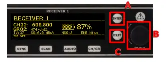
To access the receiver main menu and the sub menus press the “ENTER” button (A) or rotary knob (B). Use the “EXIT” button to exit the sub menus.
Keep pressed “ENTER” or the rotary knob pressed to confirm your selection. Scroll around the menu by using the rotary knob.
Presets
Use this to load or save presets to device. These presets include all the config. Settings. You can also restore factory settings here. Press and hold ‘enter’ button to save setting.
Receiver IF Bandwidth
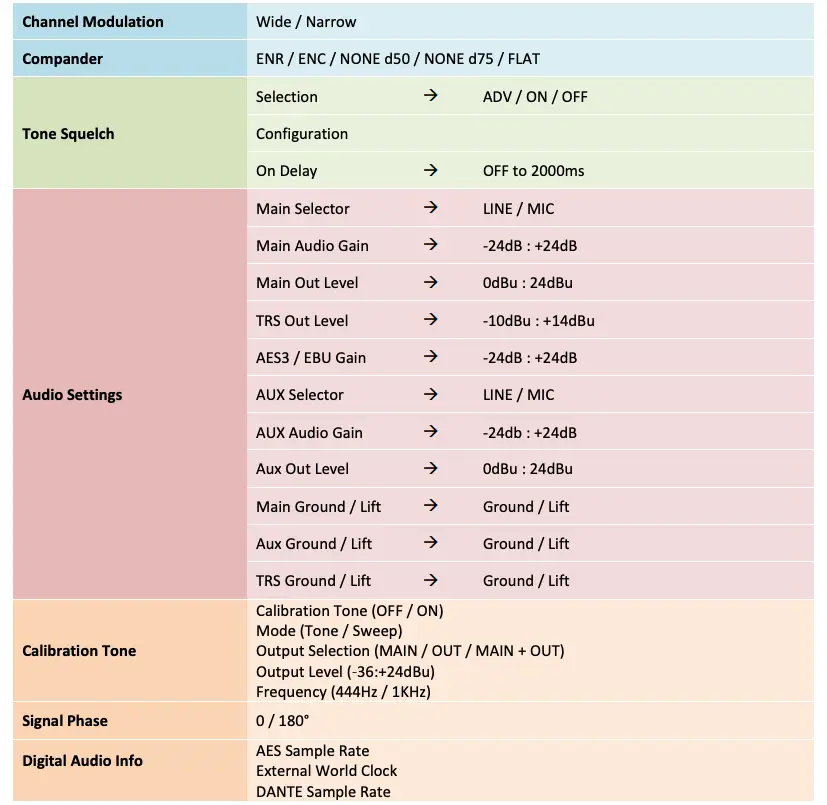
Here you can select either ‘wide’ (200kHz channel) or ‘narrow’ (100kHz channel). Make sure you are using the correct setting. If you are using with a standard Wisycom TX or a pack from another manufacturer (Sennheiser, Shure etc) then set to ‘wide’. For use with the Wisycom narrow band TX (these have the letters ‘NB’ in the manufacturer’s part number) this should be set to ‘Narrow’. N.b. Narrow band mode offers double the number of channels in a given slice of spectrum. Narrow band also increases the receiver sensitivity by 3dB, equivalent to doubling the TX power.
Squelch
From here you can set the precise RF level above which the audio will un-mute. It is set in dBuV (dB relative to 1 microvolt, therefor 0dBuV is 1uV, 6dBuV is 2uV…). This can be set manually or using the automatic squelch setting described below.
Note: If the ‘Noise Squelch’ (see below) is set to one of the levels other than ‘off’ then the audio will not un-mute unless both the squelch level set is achieved and the required noise squelch criteria is also met.
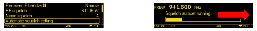
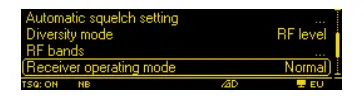
Automatic Squelch setting
This runs a sequence which measures the RF noise level on the channel. Obviously the associated TX must be off when this routine is run. It is worthy of note that the auto squelch setting is a legacy feature that is less useful when the noise squelch is used as the noise squelch tracks the noise floor as it changes and is looking for actual link quality rather than just the signal level. The recommendation therefore is to not use this feature and use a low setting of RF squelch and noise squelch.
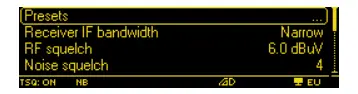
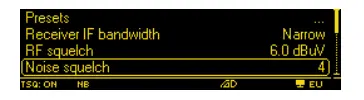
Noise Squelch
This has ‘off’ and levels 1 thru 4 available. The recommended setting is ‘1’. Noise squelch is a more powerful tool than RF squelch because it actually looks at the quality of the signal from the TX relative to the noise floor on the channel which can vary over time. With the noise squelch set to on you can set the RF squelch to a much lower level. With the noise squelch set to ‘1’ the recommended setting for the RF squelch is 3dBuV.
Note: noise squelch setting ‘1’ means a signal to noise ratio of 60dB measured before any companding. This is adequate for a reasonable link quality. Levels 2 thru 4 are for higher S/N ratios and may mean that your audio will mute when you still have a usable signal, this is why we recommend setting to ‘1’.
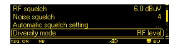
Diversity Mode
If this is set to ‘RF Level’ then the diversity antenna selection occurs based on which antenna is producing the most signal level. If it is set to ‘Channel quality’ then this choice is based upon which has the best link quality (S/N Ratio). The recommended setting is ‘Channel quality’.
Note: although it might be thought that the antennas ‘switch’ from one to the other, actually, the Wisycom true diversity system crossfades between antennas. When a similar quality of signal is being received by both antennas they are mixed together equally so any noise is reduced by 3dB thus increasing the absolute sensitivity of the receiver by the same amount.
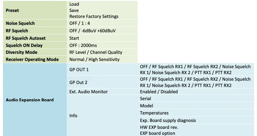
RF Bands
The RF Bands menu allows the user to manage the internal MRK980 band filtering section to increase the receiver protection level on the entire bandwidth. This matrix allows to choose for each available band either a manual or an automatic filter setup.
When the automatic selection is enabled the receiver will automatically assign itself the filter based on the band in use.
E.g. Receiver one tuned on 514.000MHz and RF Bands on AUTO: the receiver will filter the band on the UHF and exclude DME and VHF. The same if you tune the receiver one on 972.000MHz: the AUTO function will filter only DME band while excluding UHF and VHF.
Keep in Mind that the AUTO setting will affect both the RF input as well as RF output, so if you plan to use more than a unit in daisy-chain (cascade), tuned in different bands (e.g. unit 1 in UHF, unit 2 in DME), you must enable the band manually by switching ON for the bands you plan to use.
Receiver operating mode
Is selected to ‘normal’ then the receiver is working with normal sensitivity and is very immune to intermods being produced in the receiver circuits. In ‘High sensitivity’ mode then the receiver circuitry is optimized for absolute sensitivity, but there is a higher risk of intermods when lots of signals are present. The recommended setting is ‘normal’ in any situation where there are more than a handful of channels in use in the same band.

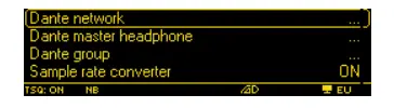
Dante
Use the Rotary knob to configure the receiver as the Headphones Master via Dante, allowing the receiver to act as a central monitoring point for your system. You can add additional Dante Groups.
Channels in the same Group can be monitored by pressing and holding the headphones button on the front panel, in the monitoring area.
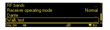
Walk test
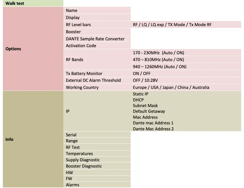
The WALK TEST function records the RF level of the two antenna inputs, separately, for a total time of 90 seconds (up to 24 hours if launched via Wisycom Manager). Using the first button, it is possible to choose what the user prefers to monitor: the antenna A or B RF Levels, max values or both antenna levels separately. To do a Walk Test press START and walk around your working area with a wireless transmitter tuned to the frequency in use on that receiver. While you do this the MRK980 will record the RF levels and gives you a clear image of the RF performance of your setup, to make you sure that there is no evidences of signal dropouts, which could compromise your wireless coverage. Once you have done, push the 3rd button (EXIT) to leave this function. The “golden rule” would be to have the signal level of “MAX AB” never lower than 20dBµV (10µV).
In case you don’t achieve this value in the walk test we suggest you to verify your cabling, the antenna boosters or change the antenna positioning.
Note: the scale for RF level is the same chosen for the Squelch level (i.e. dBuV or uV).
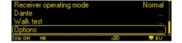
Options
This menu item allows selection, viewing of many functions:
- ‘Name’ – This shows the current name of the receiver channel that will display on the tops screen and on the software. Pressing the rotary knob allows this to be edited. It can also be edited via connected software.
- ‘Boost’ – This selects which antennas are powered for active antennas when ‘BOOSTER’ (phantom power) is selected from the front panel. This would normally be set to ‘A + B’, you would only turn the booster power off to one of the antennas if you had two different antennas and one did not need power, though this would be an unusual configuration.
- ‘TX battery monitor’ – This can be used to turn on or off the display of battery info on the top screen. This would normally be on.
- ‘Display’ – This allows setting of OLED display brightness, ‘Low timeout’ the time before the display dims and ‘OFF timeout’ sets the time before the displays turns off completely and can be set up to 4 minutes. Note: It is not possible to have the display stay on permanently as it would seriously reduce the life of the OLED.
- ‘RF LEV. Bars’ – This selects the function and behaviour of the LED bargraph (RF. LEV (dBuV) on the front panel:
- ‘RF’ – This will show the actual RF level on each of A and B antenna.
- ‘LQ’ – This will show the link quality of the signal received on each antenna. Link quality is derived from the actual signal to noise ratio from the TX on each RX antenna. This is a more useful indication than RF level as the RF level can look artificially high if there is a lot of noise on the channel.
- ‘LQ exp’ – This is as ‘LQ’ above, but the scale has been expanded so the bars reach full scale for a lower signal to noise ratio. This is useful where the system has been setup and an operator with limited RF experience is watching the unit to avoid unnecessary alarm if the display is not full scale in the normal mode. Full scale in this mode is a perfectly usable signal. The normal LQ mode only allows engineers to see a much wider dynamic range but is not needed in many instances.
- TX Mode – This is the mode that is very useful for non-skilled RF operators once the system has been setup and tested and is great for use during the actual show. This shows the RF level on the A bargraph, but with the scale expanded so that now FSD is 30dBuV and not the 70dBuV on the normal scale. Please note that this shows the RF level of the higher of either A or B antennas. The B bargraph shows the expanded LQ scale as described above and is also the best of either A or B.
- ‘TX Mode RF’ – This shows the RF level for both A and B antennas with FSD at 30dBuV and no LQ display.
- ‘Info’ – This allows the serial number, the frequency range of the unit, temperatures, internal voltages, ‘booster diagnostic’ (this is useful for checking that active antennas are drawing the correct current and that the RF feeder cable is not open or short circuit), Hardware version, Firmware version and alarms to be viewed. It also allows the IP address to be viewed and set. Also in the IP menu you can turn DHCP on or off (DHCP is useful where the MRK980 is connected to a switch with a router providing a DHCP server as it automatically allocates an IP address to the unit). You can also view the MAC address of the ethernet and Dante adaptors.
- ‘Working country’ – This enables the setting of the unit to global regions by adapting the TV Channel readout on the main display to reflect your local allocations.
- ‘RF Test’ – This gives an accurate numeric readout of the signal strength on the A and B antennas. It also displays the ‘Tsq mod’ which is the modulation level of the tone squelch from the TX. This is an engineering mode that is not usually needed in normal operation.
- ‘Activation code’ – This menu item allows the entry of a code to unlock new features or compander modes.
CHANNEL / GROUP QUICK MENU
The CHANNEL-GROUP menu enables the user to edit channel, channel group and frequency of the selected receiver. To change group (00 to 39), channel (00 to 59) or frequency scroll the rotary knob until you find the desired one, then keep ENTER pressed to confirm or EXIT cancel. To edit the frequency of the selected channel (it must be UNLOCKED to be modified), press the middle button and change it with the knob (25Khz steps). Press the knob to move between MHz and KHz. Confirm or exit with the buttons. Note that the modified frequency will be saved into the MRK98 frequency plan, shared by both Rx1 and Rx2, so be sure to select a different channel/group for each receiver when tuning frequency manually or both receivers will be tuned to the same frequency.
Connecting with your computer to the device via Wisycom Manager helps speed up the frequency management procedure, with several dedicated functions and a user friendly interface.
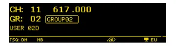
Group name
The first line inside the Options Menu is GROUP NAME; with this function it is possible to assign or change the name of a group of channels. This short name (8 characters) is displayed to the right of the group number in the main display overview.
First chose the group and then press the knob to confirm. You will be able to edit any character of the group name by rotating the knob. Push the knob to edit the next character and the keep pressed ENTER to confirm or EXIT to cancel.
As shown in the above picture, the display area has 3 rows with:

- Channel number (0 to 60) and Channel frequency (in 25kHz step)
- Group number (1 to 40) and group name (8 char.)
- Group description (30 char.)
The MRK980 has 40 groups of 60 channels each which means 2400 preloaded frequencies, more than any other wireless microphones system.
By connecting through the PC with the Wisycom Manager, it is possible to hide/unhide single channels or even complete groups of channels: once hidden those items are not shown any more on the channels or groupsselection on the device.
With this software it is also possible to lock/unlock channels or groups: when a channel is locked, it is not possible to change the frequency from the receiver CH/GR menu. Locking a group will lock all the channels contained within it.
When a channel or a group is locked, at the left of the group name in the Chan-Group menu will appear a “Lock” icon. When the lock picture is shown, the central button is not displayed, so changing frequency is not possible.
AUDIO MENU
This menu item allows selection, viewing of many functions:
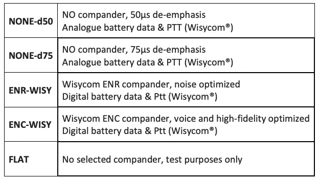
‘Compander’ – This enables the setting of the Compander you want to work with. The MRK980 features a multiple compander system which includes Wisycom ENR and ENC plus various other companders which allow you to work with a large range of transmitters. Thanks to the DSP board, it is possible to choose different types of audio processors. MRK980 supports, as standard configuration, the following type of “Companding system”:
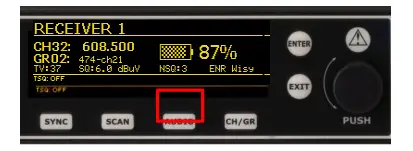
Use the buttons to save or exit from this function. Depending on selected noise reduction system, tone squelch function and transmitter battery status could be enabled or disabled (since not all the wireless microphones have this enhanced functionality).
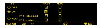
‘Tone Squelch’ – This function is an advanced option whose behavior depends on the selected noise reduction system. This chapter explains Tone Squelch operations when associated with a Wisycom wireless microphone with the ENR-WISY or ENC-WISY as active noise reduction system. Other types of wireless microphones could have different behavior or could not work properly. The tone squelch selection could be OFF, ON or ADV (advanced). After ‘SAVE’ of tone squelch is selected, a CONFIG submenu appears on the right. Enter on the CONFIG submenu to change the setting of the chosen Tone Squelch (see matrix below).
With the knob and the buttons, it is possible to choose, for any one of the three TSQ modes, the status of the audio outputs LINE and COM and in the TSQ ADV mode it is possible to choose the audio routing to outputs LINE and AUX, when the transmitter PTT button is either pressed or released. The dot in the circle on the left of the display shows the actual setting off the tone squelch function.
Tone Squelch OFF enables the audio output on LINE and AUX connectors even when no pilot tone is received from the TX, it will be muted only by the Noise and/or the RF level squelch if signal is not good enough.
Tone Squelch ON enables the audio output on LINE and AUX only if the transmitter sends the correct identification pilot tone signal (Tone Squelch).
Tone Squelch ADV on transmitters, this gives more options for audio routing and GPI signaling (GPI only if Expansion board EXP1 is installed)
Note: Tone Squelch doesn’t replace RF squelch or Noise Squelch. For the best performances remember to use Tone Squelch together with at least one of the two options above or, preferably all three (e.g. Tone Squelch ON and RF Squelch @ 6BuV).
TREE MENU
MAIN MENU
AUDIO MENU
SAFETY INSTRUCTION
- Read this safety instruction and the manual first.
- Follow all instructions and information.
- Do not lose this manual.
- Do not use this apparatus in the rain or near water.
- ATTENTION: supply the apparatus with the correct mains voltage and with the ground connection. Check the power cord integrity.
- The power cord must be protected from damage.
- Do not install the apparatus near heaters or in hot environments, do not use outside the operating temperature range.
- Mount the apparatus as indicated in the instruction, do not block side grilles from air ventilation.
- If an external air filter is mounted, clean it regularly.
- WARNING: do not open the apparatus, RISK OF ELECTRIC SHOCK!
- Do not open the apparatus, only qualified service technicians are authorized to work on it. The apparatus needs servicing when is not working properly or is damaged by liquids, moisture or other objects have fallen into the apparatus.
- Use only accessories or replacement parts authorized or specified by the manufacturer.
- Do not supply more than seven MRK980 from the mains output, see power requirements for other apparatus.
- Clean the apparatus only with dry cloths, do not use liquids.
- The ON/OFF is a double pole circuit breaker, but to ensure the complete disconnection of the apparatus, disconnect the power cord.
- Provide the serial number and the purchasing date in front of the manual, it is needed to have proper replacement parts or accessories from the manufacturer.
- When replacement parts are needed, use only replacement parts authorized by the manufacturer. Substitution with not authorized parts could result in electric shock, hazards or fire.
- Pay attention to all the labels with warnings or hazards on the apparatus.
- WARNING: The apparatus is intended for professional use, anyway the manufacturer alerts the user that the headphone output power of the apparatus could exceed the level of 85 dB(A) of sound pressure level and this could be dangerous for hearings. Do not use headphones with high power level or for a long time. Reduce the power or stop listening in case of any kind of hearing problem.
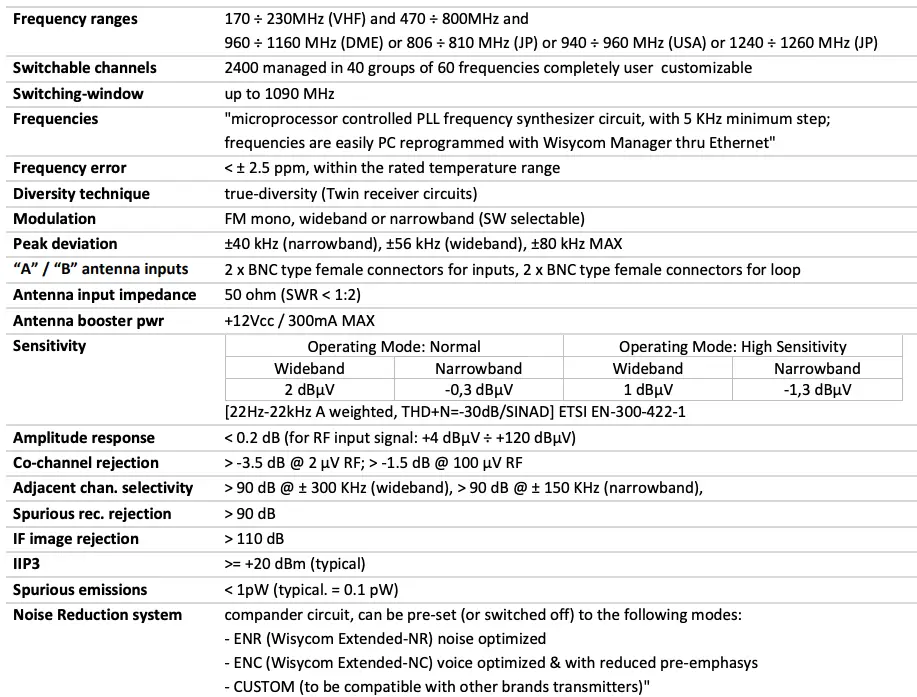
TECHNICAL SPECIFICATIONS
![]()
Via Tiepolo 7/E • 35019 Tombolo (PD) • Italy
Tel. +39 -0424 -382605 • Fax +39 – 0424 – 382733
www.wisycom.com • e-mail: [email protected]