![]()
OWNER’S MANUAL
TWO-CHANNEL AMPLIFIER
![]()
ABR-200.2
CLASS AB BURAN SERIES
https://alphard.audio
![]()
INTRODUCTION
Thank you for purchasing this Avatar product! Our company is committed to the creation of extremely loud systems with no loss of quality.
To ensure proper use, please carefully read through this manual before using this product. It is especially important that you read and observe the caution’s in this manual. Please keep the manual in a safe and accessible place for future reference.
SAFETY INSTRUCTIONS
- Make sure that your vehicle has a 12V DC electrical system with negative grounding. Before installing the amplifier in cars, trucks or buses, check the battery voltage.
- Check the state of the onboard power supply of your vehicle, the battery, and the alternator. When the engine is running, depending on the ambient temperature, the voltage to be outputted by the alternator must be within the range of 14 to 14.7 V. Open circuit voltage (OCV) of the battery must be within the range of 12.5 to 13 V. Make sure that the rated current of the alternator and the battery capacity is enough to provide increased consumption.
For example, for the power of the amplifier 1000 W, the rated current of the alternator is required at the rate of 1000 W / 13 V = 77 amperes. A more powerful amplifier requires a more powerful alternator as well as an additional battery. - Do not place the amplifier in the engine compartment and also in the places exposed to water, moisture, dust or dirt.
- Never stretch the cables outside of the car and near the moving parts of the car. This can lead to destruction of the insulating layer, short circuit and fire.
- The amplifier should be installed in areas of the car where the temperature varies from 0 °C (32 °F) to 55 °C (131 °F). The amplifier should be in a place with a good air circulation. The horizontal position of the amplifier is the best way to install.
- During the operation the amplifier may be heated up to 80 °C (176 °F). Before you touch it, make sure it is not overheated that may be dangerous.
- To improve the cooling of the amplifier, it is recommended to clean periodically the heatsink from dust. When cleaning the heatsink strong solvents should not be used as they may damage the amplifier. Do not use compressed air, because solids can penetrate inside the amplifier. Cleanings best done with wet towels or cloth.
- Make sure that the location of the amplifier does not violate the proper operation of mechanical and electrical devices of the vehicle.
- Make sure that during the installation and connection of the battery, the power cables are not shorted.
- When performing plumbing, drilling or cutting works with the car, make sure that there is no wiring, brake lines, fuel pipe or other structural elements under the place of work. Follow the safety rules! Use protective glasses and gloves.
- To protect the wires use rubber gaskets if the wire passes through a hole in the plate, or other similar materials if it lies close to the parts exposed to heat.
- Make sure that all the cables are fixed over the entire length. Also make sure that their outer protective shell is noncombustible. Use a clamping screw to secure the positive and negative cables next to the appropriate terminals of the amplifier.
- Select a diameter of the power cable in accordance with the power of the amplifier and the recommendations provided here. Power cables are extremely important since they directly affect the system damping factor and sound quality. The cables to the battery must be in the copper crimp terminals pressed with the help of a hydraulic press, and well fixed to the battery terminals.
- To avoid accidental damage, keep the amplifier in its original packaging prior to installation.
- Use high-quality copper speaker and power cables.
CAUTION!!! High sound pressure can damage your health! Please use the common sense when controlling volume!
TYPICAL INSTALLATION SEQUENCE
- Before installing the amplifier disconnect the battery from the electrical system.
- To connect the amplifier it is necessary to stretch the power cable from the location of the battery to the place of installation of the amplifier. Select the power cable with the appropriate regulations in AWG (see Table: Selection of the diameter of the power cables)
- Connect the power supply with the correct polarity. Connect all (+) terminals of the amplifier to the cables stretching from the positive terminal of the battery and all (-) terminals of the amplifier to the cables stretching from the negative terminal of the battery.
- Place the fuse holder for each positive cable within 40 cm from the positive terminal of the battery and connect one end of the power cable to the holder after connecting the other end to the amplifier. Do not install the fuse.
- Route all signal cables next to each other and separately from the power cables.
- Connect the wires of RCA input. The input signal power must be between 0.2V and 6V.
- To connect the power wire supply is necessary to use special power cables.
- Fasten the amplifier properly when installing it in the vehicle. If the component is disconnected during driving, it may cause serious damage to the passengers of the vehicle or another vehicle. It is not recommended to screw the amplifier directly to the metal it can lead to distorsions at the signal outputs.
- After installation is complete, check the wiring of the system and make sure that all connections have been made correctly. Before installing the fuses, disconnect the positive lead from the battery and then install the fuse in the fuse holder. Using the light bulb 12V 21W, connect the positive lead to one contact of the bulb and the other contact of the bulb to the positive terminal of the battery. When properly connected, the bulb must briefly light up and go out. Now you may connect the positive lead to the (+) of the battery. If the light does not go out, then something is wrong. This will prevent damage to the amplifier in case of reverse polarity and unwanted sparks when connecting. Install the rest of the fuses.
- To activate the amplifier, it is necessary to apply the positive potential of 12V to the control input of the amplifier (REM) through a switch or a corresponding control output (REMOTE OUT) with the head unit (HU).
- LED indicator on front of the amplifier turns green to indicate that the amplifier is turned on. If the indicator does not light up see chapter “Possible faults and their solutions” for more information.
- The sound level is calibrated by adjusting the volume of the source up to 3/4 of its maximum level. Then, adjust the sensitivity level of the amplifier up until you hear distortions.
SELECTION OF THE DIAMETER OF POWER CABLES AND SPEAKER CABLES EN
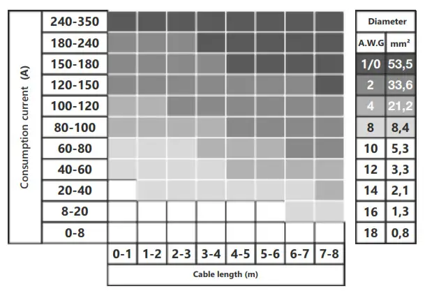
Selection of the diameter of the power cables
Use the table below to select the desired diameter based on the length and the current consumption.
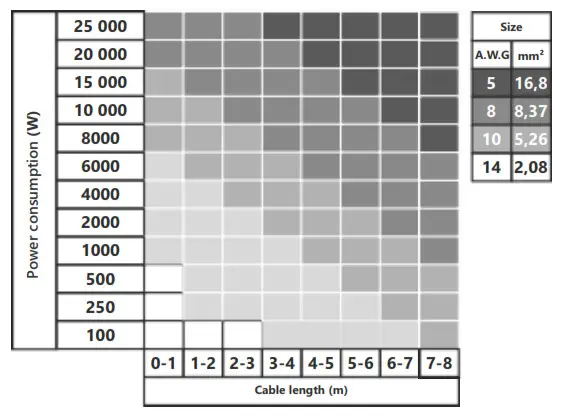
 Selection of the diameter of the speaker cables
Use the table below to select the desired diameter based on the length and the power consumption.
WIRING DIAGRAMS
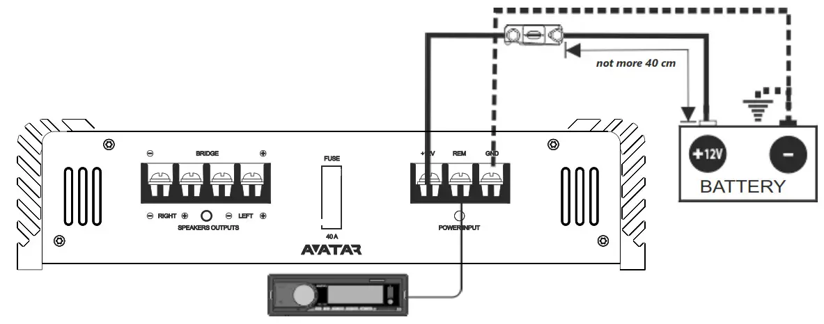
Connect the speaker cables from the positive and negative terminals of the speakers to the respective outputs of the amplifier terminal marked with right / left speakers outputs as shown at the diagram. To connect the power wire supply it is necessary to use special power cables. The fuse is placed in the holder and fixed in the cable cut. One end of the cable is connected to the positive terminal of the battery, the second one to the amplifier terminals marked with +12V. Be sure to use a fuse with the parameters sufficient for use in the system. The length and diameter of the grounding cable must conform to the length and diameter of the cable +12V. Connect one end to the negative terminal of the battery and the other end of the grounding cable to the terminals marked with GND. Connect the head unit (HU) to low-level inputs of the amplifier using RCA cable.
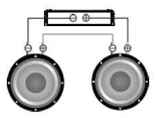
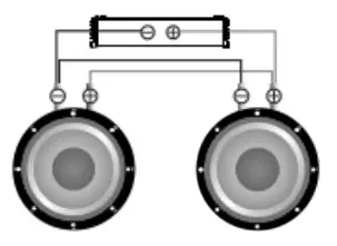
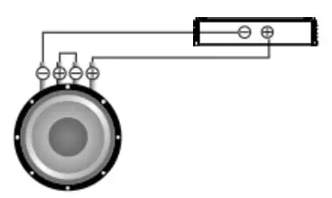
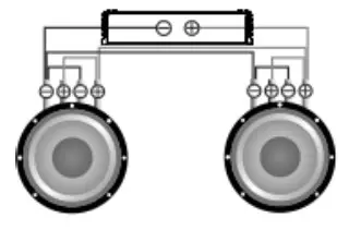
Standard wiring diagram of two-channel amplifier to two speakers.
Step 1. Connect the speaker cable from (+) terminal of the amplifier to (+) terminal of the speaker.
Step 2. Connect the speaker cable from (-) terminal of the amplifier to (-) terminal of the speaker.
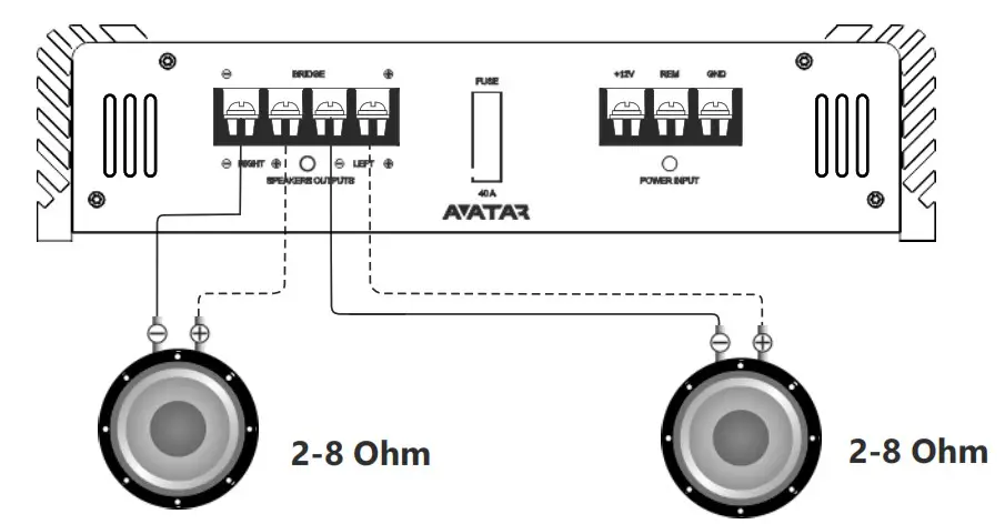
Caution!!! The minimum permissible connection load impedance at every single channel is 2 ohm. For model ABR-200.2 the operating voltage is 9-15V.
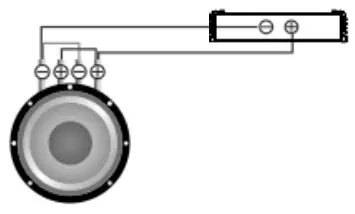
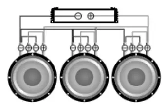
Standard wiring diagram of two-channel amplifier to one subwoofer
Step 1. Connect the speaker cable from (+) terminal of the amplifier to (+) terminal of the subwoofer.
Step 2. Connect the speaker cable from (-) terminal of the amplifier to (-) terminal of the subwoofer.
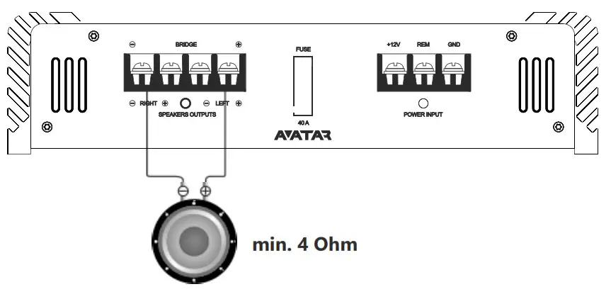 Caution!!! The minimum permissible connection load impedance for bridged connection is 4 ohm. For model ABR-200.2 the operating voltage is 9-15 V.
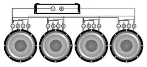
Standard wiring diagram of two-channel amplifier to battery
Step 1. Connect one end of the power cable from (+) terminal of the battery and the second end to the amplifier terminal marked with +12V. Do not forget to protect positive power cable with appropriate fuse.
Step 2. Connect one end of the power cable from (-) terminal of the battery and the second end of the grounding cable to the terminals marked with GND.
Step 3. Connect one end of the cable to the Remote output terminal at the HU and the second end to the amplifier terminal marked with REM.
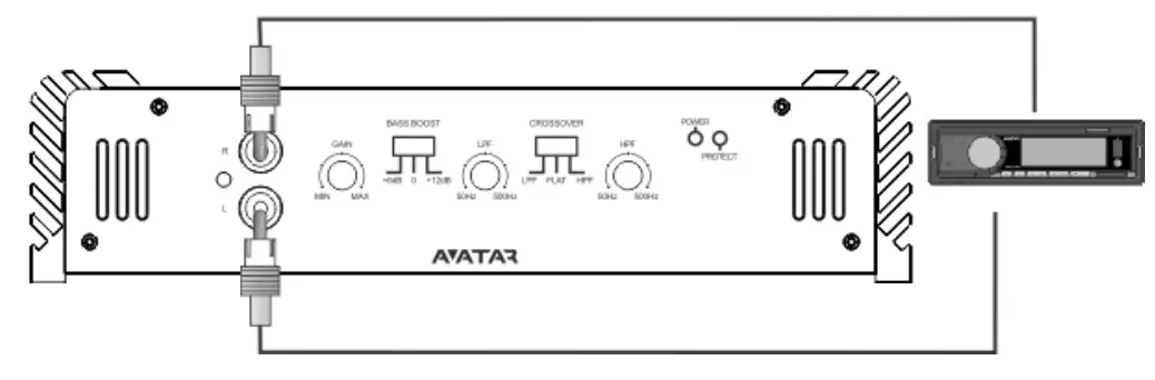
 Standard wiring diagram of the two-channel amplifier to Head Unit
Step 1. Connect one end of the RCA cable to the RCA output terminals at the HU and the second end to the amplifier RCA inputs terminals marked with INPUT.
 Application of connectors and controls
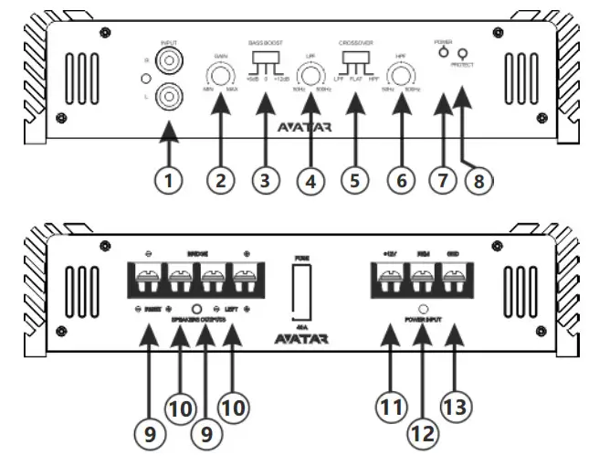
- INPUT signal input, RCA jacks
- GAIN input signal level adjustment 0.2V – 6V
- BASS BOOST bass level adjustment 0/+6/+12 dB at 45 Hz
- LPF low pass filter 50 Hz -500 Hz (12 dB/Oct)
- CROSSOVER selection of built-in filters operating mode (LPF, FLAT, HPF)
- HPF high pass filter 50 Hz – 500 Hz (12 dB/Oct)
- POWER – LED for operation (green)
- PROTECT – LED for protection (red)
- SPEAKERS OUTPUTS “+” speakers positive terminal connections
- SPEAKERS OUTPUTS “-” speakers negative terminal connections 1
- +12V power supply terminal (+12V)
- REM connector of remote activation of the amplifier
- GND grounding supply terminal «-»
CONNECTION METHODS
The minimum permissible load impedance at the output of the amplifier is 2 ohm.
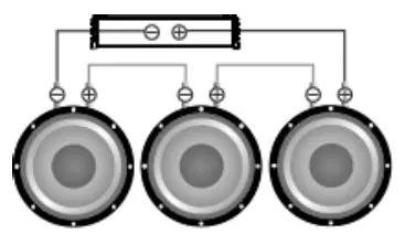
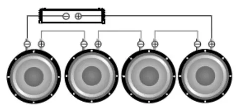
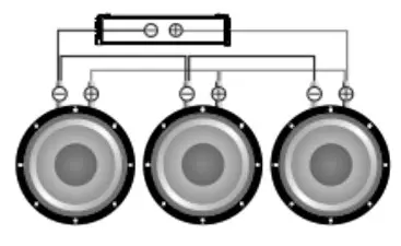
SPEAKERS WIRING DIAGRAMS
In any case do not expose the amplifier to loads lower than specified by the manufacturer. Use these schematics to calculate load impedance of different connection types.
Serial connection of the speakers
| Voice coil | Total impedance |
| 4 Ohm | 8 Ohm |
| 8 Ohm | 16 Ohm |
| Voice coil | Total impedance |
| 4 Ohm | 12 Ohm |
| 8 Ohm | 24 Ohm |
| Voice coil | Total impedance |
| 4 Ohm | 16 Ohm |
| 8 Ohm | 32 Ohm |
Parallel connection of the speakers
| Voice coil | Total impedance |
| 4 Ohm | 2 Ohm |
| 8 Ohm | 4 Ohm |
| Voice coil | Total impedance |
| 4 Ohm | 1.33 Ohm |
| 8 Ohm | 2.66 Ohm |
| Voice coil | Total impedance |
| 4 Ohm | 1 Ohm |
| 8 Ohm | 2 Ohm |
Mixed connection of the speakers
| Voice coil | Total impedance |
| 4 Ohm | 4 Ohm |
| 8 Ohm | 8 Ohm |
CAUTION!!! High sound pressure can damage your health! Please use common sense when controlling volume!
SUBWOOFERS WIRING DIAGRAMS
The minimum permissible load impedance at the output of the amplifier is 2 ohm. Use these formulas to calculate the load impedance of various types of connections.
Series connection
Total impedance=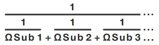
SCHEMES OF ENABLING THE LOAD OF THE SUBWOOFER
In any case do not expose the amplifier to the loads lower than specified by the manufacturer. Use these schematics to calculate load impedance of different connection types.
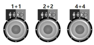
Voice coils 1+1, 2+2, 4+4 Ohm
The subwoofer has voice coil D1, D2 or D4.
One subwoofer, coils in series
| Voice coil | Total impedance |
| 1+1 Ohm | 2 Ohm |
| 2+2 Ohm | 4 Ohm |
| 4+4 Ohm | 8 Ohm |
One subwoofer, coils in parallel
| Voice coil | Total impedance |
| 1+1 Ohm | 0.5 Ohm |
| 2+2 Ohm | 1 Ohm |
| 4+4 Ohm | 2 Ohm |
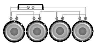
Subwoofers in series, coils in parallel
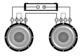
| Voice coil | Total impedance |
| 1+1 Ohm | 1 Ohm |
| 2+2 Ohm | 2 Ohm |
| 4+4 Ohm | 4 Ohm |
| Voice coil | Total impedance |
| 1+1 Ohm | 1.5 Ohm |
| 2+2 Ohm | 3 Ohm |
| 4+4 Ohm | 6 Ohm |
| Voice coil | Total impedance |
| 1+1 Ohm | 2 Ohm |
| 2+2 Ohm | 4 Ohm |
| 4+4 Ohm | 8 Ohm |
Subwoofers in series, coils in series
| Voice coil | Total impedance |
| 1+1 Ohm | 4 Ohm |
| 2+2 Ohm | 8 Ohm |
| 4+4 Ohm | 16 Ohm |
| Voice coil | Total impedance |
| 1+1 Ohm | 6 Ohm |
| 2+2 Ohm | 12 Ohm |
| 4+4 Ohm | 24 Ohm |
| Voice coil | Total impedance |
| 1+1 Ohm | 8 Ohm |
| 2+2 Ohm | 16 Ohm |
| 4+4 Ohm | 32 Ohm |
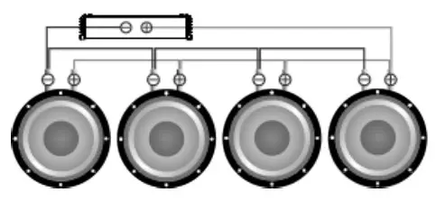
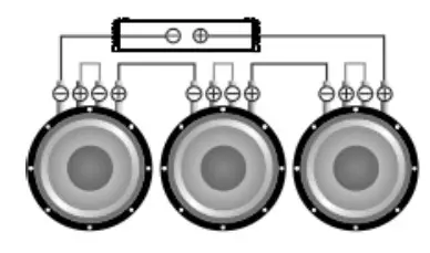
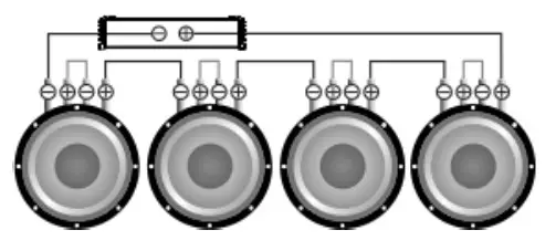
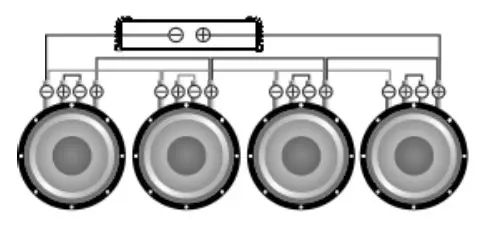
Subwoofers in parallel, coils in series
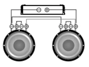
| Voice coil | Total impedance |
| 1+1 Ohm | 1 Ohm |
| 2+2 Ohm | 2 Ohm |
| 4+4 Ohm | 4 Ohm |
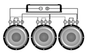
| Voice coil | Total impedance |
| 1+1 Ohm | 0.66 Ohm |
| 2+2 Ohm | 1.33 Ohm |
| 4+4 Ohm | 2.6 Ohm |
| Voice coil | Total impedance |
| 1+1 Ohm | 0.5 Ohm |
| 2+2 Ohm | 1 Ohm |
| 4+4 Ohm | 2 Ohm |
| Voice coil | Total impedance |
| 1+1 Ohm | 0.25 Ohm |
| 2+2 Ohm | 0.5 Ohm |
| 4+4 Ohm | 1 Ohm |
| Voice coil | Total impedance |
| 1+1 Ohm | 0.16 Ohm |
| 2+2 Ohm | 0.33 Ohm |
| 4+4 Ohm | 0.66 Ohm |
| Voice coil | Total impedance |
| 1+1 Ohm | 0.125 Ohm |
| 2+2 Ohm | 0.25 Ohm |
| 4+4 Ohm | 0.5 Ohm |
CAUTION!!! High sound pressure can damage your health! Please use the common sense when controlling volume!
SPECIFICATIONS
| Model | ABR-200.2 |
| Power RMS 4 Ohm* (W) | 80 x 2 |
| Power RMS 2 Ohm* (W) | 100 x 2 |
| Power RMS 4 Ohm bridged mode* (W) | 200 х 1 |
| High pass filter (Hz) | 50 – 500 |
| Low pass filter (Hz) | 50 – 500 |
| Crossover (dB/Oct) | 12 |
| Bass level adjustment (dB at 45 Hz) | 0/+6/+12 |
| Frequency response (Hz) | 10 – 20 000 |
| Input sensitivity (V) | 0.2 – 6 |
| Signal to noise ratio (dB) | > 92 |
| Damping factor | > 170 |
| Input terminal connection (AWG/)mm² | 6 / 13.3 |
| Output terminal connection (AWG/ mm²) | 14 / 2.08 |
| Working voltage (V) | 9-15 |
| Minimum permissible load on the single channel (Ohm) | 2 |
| Minimum permissible load in a bridged mode (Ohm) | 4 |
| Size (LхWхH mm) | 270 x 220 х 50 |
| Size (LхWхH inch) | 10.63 x 8.66 х 1.97 |
*RMS Power at 14.4 V, THD 1%
POSSIBLE FAULTS AND THEIR SOLUTIONS
Avatar amplifiers are high-quality and technically perfect products. The problems often arise due to improper use, faulty connection of components or lack of power supply of the on-board network.
- The amplifier does not turn on. Problem solution: check all the contacts and the presence of 9-15V the amplifier terminals. Check whether the control input of the amplifier “REM” receives the positive potential of +12V.
- Power turns on, but goes into protection (protection indicator lights up). Problem solution: check if there is a short circuit (fault) on the amplifier output which is connected to the speakers. Make sure that commutation of the voice coils of the speakers is correct. The rated impedance of the voice coils should not be lower than the permissible rated load impedance of the amplifier. Check the supply voltage of the amplifier. It must be within the range of 9-15V.
- The amplifier turns on but at a high volume it goes in to protection. Problem solution: The amplifier may lack power. Make sure that the rated current of the alternator and the battery capacity is enough to power this amplifier. Check the amplifier for overheating. Check the load impedance.
- The amplifier is turned on, but there is no sound from the speakers. Problem solution: check the connection of the amplifier, the integrity of the interconnecting cable, HU or speakers.
BOX CONTENT
- Amplifier 1 pc.
- Owner’s Manual 1 pc.
- Warranty card 1 pc.
- Mounting Kit 1 pc.
WARRANTY AND MAINTENANCE INFO
Avatar products are warranted against defects concerning materials and their manufacturing under normal functioning conditions.
While the product is under warranty, defective parts will be repaired or replaced at the manufacturer’s discretion. The defective product, along with notification about it, must be returned to the dealer from which it was purchased together with the warranty certificate duly filled in, complete with the original packaging. If the product is no longer under warranty, it will be repaired at the current costs.
Our company does not undertake any liability for damages due to transportation. Our company does not take any responsibility for: costs or loss of profit due to the impossibility to use the product, other accidental or consequential costs, expenses or damages suffered by the customer. Warranty according to laws in force. For more information visit our website and carefully read warranty card. The manufacturer reserves the right to change design and specification without prior notice.
INFORMATION ON DISPOSAL OF THE ELECTRICAL AND ELECTRONIC EQUIPMENT (FOR THE EUROPEAN COUNTRIES WITH SEPARATE WASTE COLLECTION).
Items marked “crisscrossed wheeled bin” are not allowed to be disposed of together with usual household waste. These electrical and electronic products should be disposed of in special reception centers, equipped for recycling such products and components. For information about the location of the nearest disposal / recycling spot and the rules of delivery of waste please contact your local municipal office. Recycling and proper disposal helps to protect the environment and prevent harmful effects on health.
]]>
User Manual
Read this owner’s manual thoroughly before operating the I appliance and keep it handy for reference at all times.
![]()
![]()
SAFETY INSTRUCTIONS
The following safety guidelines are intended to prevent unforeseen risks or damage from unsafe or incorrect operation of the appliance. The guidelines are separated into ‘WARNING’ and ‘CAUTION’ as described below.
This symbol is displayed to indicate matters and operations that can cause risk. Read the part with this symbol carefully and follow the instructions in order to avoid risk.
 WARNING
This indicates that the failure to follow the instructions can cause serious injury or death.
CAUTION
This indicates that the failure to follow the instructions can cause a minor injury or damage to the product.
IMPORTANT SAFETY INSTRUCTIONS
WARNING
To reduce the risk of explosion, fire, death, electric shock, injury or scalding to persons when using this product, follow basic precautions, including the following:
Children in the Household
This appliance is not intended for use by persons (including children) with reduced physical, sensory or mental capabilities, or lack of experience and knowledge unless they have been given supervision or instruction concerning the use of the appliance by a person responsible for their safety. Children should be supervised to ensure that they do not play with the appliance.
Installation
- Electrical or installation work needs to be performed by qualified service personnel.
- Do not install the appliance less than 2.3 m from the ground and 1 m from the wall to the blades.
- Do not install the appliance with a dimmer switch.
- Ensure that the ceiling hook can sustain more than 10 times the appliance weight.
- Ensure that the shaft has been fully tightening to the motor shaft and
- Firmly tighten the blade screws using a screwdriver.
- Do not install the appliance in a place where flammable liquids or gases such as gasoline, propane, paint thinner, etc., are stored.
- Do not install the appliance somewhere exposed to direct sunlight.
- Do not install the appliance in an area prone to combustible gas leaks, grease, or metal dust.
Operation
- Connect this appliance as per the rated voltage and frequency printed on the nameplate.
- Do not touch the power switch with wet hands.
- Do not disassemble, repair, modify or touch the appliance while it is
- Do not insert hands or any objects into the appliance.
- Do not place any objects on the appliance.
- Do not use or store flammable or combustible substances (ether, benzene, alcohol, chemical, LPG, combustible spray, insecticide, air freshener, cosmetics, etc.) near the appliance.
- If there is a gas leakage [isobutane, propane, natural gas, etc.), do not touch the appliance or power switch and ventilate the area immediately.
- Cut off the power supply if there is any noise, smell, or smoke coming from the appliance.
- Do not expose the appliance to splashing water or rain.
- Do not touch, operate, or repair the appliance with wet hands.
- Dispose of all packaging materials (such as plastic bags and Styrofoam) away from children. The packaging materials can cause
Maintenance
- Before cleaning or performing maintenance, disconnect the power supply and wait until the blade stops.
- Do not use an abrasive cloth, sponge, or a metal brush to clean the
Battery
- 2 MA batteries are used in the remote controller of the appliance. This battery is not rechargeable. May explode or leak if charged, connected reversely, disposed of in fire.
- Replace all batteries in the remote controller with new ones of the same type. Do not mix old and new batteries or different types of batteries
CAUTION
To reduce the risk of minor injury to persons, malfunction, or damage to the product or property when using this product, follow basic precautions, including the following:
Installation
- Do not install the appliance at a wet, high temperature, high humidity area, high vibration, windy places.
- Do not install the appliance in freezing temperature.
- Do not install the appliance on or near items that may be damaged or discolored by heat or humidity.
- Do not install the appliance near curtains.
- Do not install the appliance within 1 m of a TV or stereo equipment. It may cause interference.
- After installation make sure the appliance does not tremble
Operation
- Do not use the appliance in place of a vent hood. Doing so will shorten the appliance’s lifespan.
- Do not operate in an area with unstable voltage, the appliance may automatically shut down to protect appliance components.
- This appliance is intended to be used in household and domestic applications only and must not be used for commercial purposes.
Maintenance
- Replace all the blades if any of them breaks or cracks.
- Never use strong cleaning agents or solvents when cleaning the Use a smooth cloth.
- Use a sturdy stool or ladder, when cleaning, maintaining or repairing the ceiling fan at height.
Battery
- Do not modify the battery arbitrarily.
- Misplaced battery may cause an explosion.
- Do not recharge or take apart the battery.
- Do not throw the battery in the fire for disposal or leave it near the
- Remove and store the battery in a safe location if you don’t intend to use the remote controller for a long time.
PRODUCT OVERVIEW
Parts and Accessories
![]()
Accessories
Thank you for purchasing our smart ceiling fan! Please check the accessories list immediately after unpacking.
| Parameters | Values | |
| Model Number | AFL44L | AFL5OL |
| Item Weight(Net) | 12.5 pounds | 12.7 pounds |
| Size | 44 inches | 50 inches |
| Color | Matte Black, Wood Grain Blades | |
| Style | Contemporary | |
| Material | Metal, Wood Laminate | |
| Power Source | AC | |
| Voltage | 120 Volts | |
| Wattage | 25 watts | |
| Type of Source | LED Panel. 24 watts | |
| Luminous Flux | 1800 Lumen | |
| Lamp Temp. | 3000K | |
| Plug Profile | Downrod Mount | |
| Usage | Ceiling Fan | |
| Batteries Included? | Yes, AAA 1.5V x 2PCS | |
| Special Features | Reversible Airflow Remote Control App Control Anywhere Works with Amazon Alexa Works with Google Assistant |
|
NOTE
Specified weight may differ from the actual weight.
INSTALLATION GUIDE
Tools Required
![]()
If there is no existing mounting box, then read the following instructions. Disconnect the power by removing the fuses or by turning off the circuit breakers.
Secured the outlet box directly to the building structure. Use appropriate fasteners and building materials. The outlet box and its support must be able to fully support the moving weight of the fan(at least 35 Ibs]. Do not use plastic outlet boxes.
WARNING
To reduce the risk of fire, electric shock, or another personal injury, mount fan only to an outlet box marked acceptable for fan support and use the mounting screws provided with the outlet box outlet boxes commonly used for the support of lighting fixtures may not be acceptable for fan support and may need to be replaced. Consult a qualified electrician if in doubt.
Hanger Options
To avoid possible electrical shock, before installing your fan, disconnect the power by turning off the circuit breakers to the outlet box associated with the Wall switch location.
a. Installing the mounting bracket
Step 1. Pass the power wires through the hole in the mounting bracket as shown in Fig.1.
Step2. Secure the mounting bracket to the ceiling outlet box with the wood screws and falt washer provided with your outlet box.
![]()
b.Installing the mounting bracket
When the case of concrete ceiling, use a drill hole drilled in the ceiling of two 08 (distance between the two holes should be appropriate), expansion screw into the hole, then put the mounting bracket expansion screw set into the tum flat washers and nuts and tighten with a spanner.
![]()
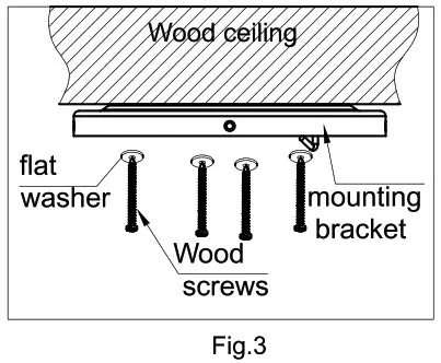
c.Installing the mounting bracket
The ceiling is made of wood, please lock with a screwdriver mounting bracket on the ceiling[Figure 3), Parts bag flat washer set into the wood screws.
![]()
Hanging Motor housing
Lift the Motor housing and hang it on the hook of the mounting bracket.![]()
Wiring (continued)
![]()
- Connect the 2 grounding wires (green, green/yellow stripe, or bare copper) coming from the ceiling, download, and hanger.
- Connect the white wire from the receiver to the white wire from the fan.
- Connect the blue wire from the receiver to the blue wire from the fan.
- Connect the UVW wire from the receiver to the UVW wire from the
- Connect the blue wire from the receiver to the white wire from the
- Connect the brown wire from the receiver to the black wire from the ceiling.
The controller installation
Put the controller in the Motor housing after the wire is connected
![]()
Installing Motor housing
Remove the motor housing from the hook and align it with the mounting bracket hole of the suspension plate and tighten it with screws.
![]()
Attaching the Fan Blades
Place each blade between a blade iron and medallion. install three-blade screws and washers, found in the hardware bag, to attach the medallion to the blade iron. Repeat steps for the remaining blades.
![]()
Blade assembly installation
- Remove blade iron screws from fan motor
- Attach the blade irons to the motor with blade iron screws
- Repeat this step for each blade assembly
![]()
Switch housing installation
- Feed the wire through the center hole of the switch housing
- Attach the switch housing to the motor with screws
![]()
The LED installation
- Connect the wire from fan to the LED. Blue to black, white to white
- The LED is attracted to the switch housing by a magnet
![]()
The lampshade installation
Beand the lampshade properly and then put it in the switch housing.
![]()
Remote Configuration
- Diagram of Remote
- How to pair a smart ceiling fan with a remote controller?
When the ceiling fan is powered on, you will hear a sound of “beep” in 3 seconds, press the key of the PAIR CODE until you hear two sounds of “beep beep”, done.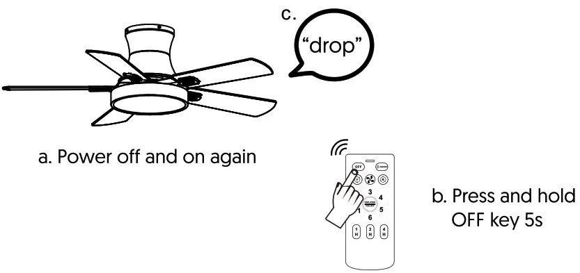
APP Connection
- Download AvatarControls App
Download AvatarControls from Apple Store or Google Play Store or scan the OR code below to install the Avatar Controls APP for either iOS or Android.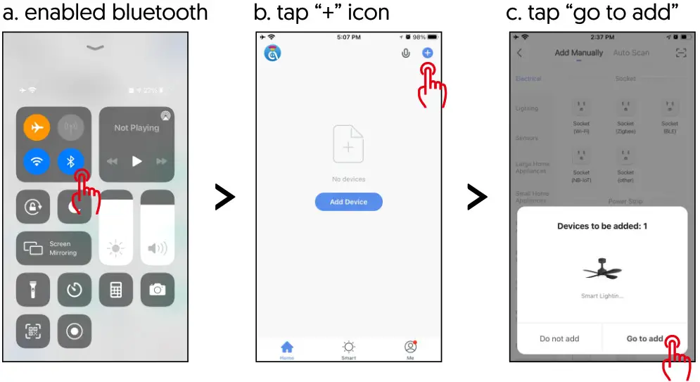
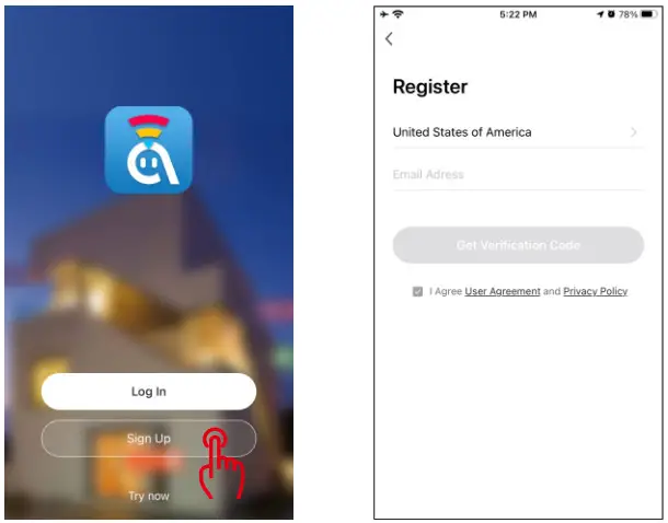
https://smartapp.tuya.com/avatarsmarthome - Register an account in AvatarControls APP
•Open AvatarControls APP into account registration page, click on the “Sign Up”
•At the registration page, select your region and enter the email to create a new account.
•After successful registration, you can add a device on your APP now.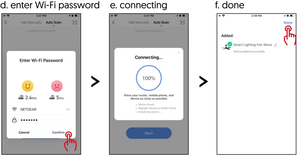
- Activate smart ceiling fan to network paring mode Power on the smart ceiling fan again, then press the remote OFF key for 5 seconds until the smart ceiling fan makes a “drop” sound, that’s mean the smart ceiling fan has entered the network pairing mode.
- Add device in AvatarcontrolsApp
 NOTE: The router WiFi can not be set to the hidden state, and the WiFi must be 2.4G network. The product does not support 5G network temporarily. The WiFi hidden state controller cannot be successfully distributed, and the router WiFi name must be in English
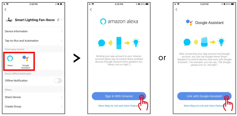
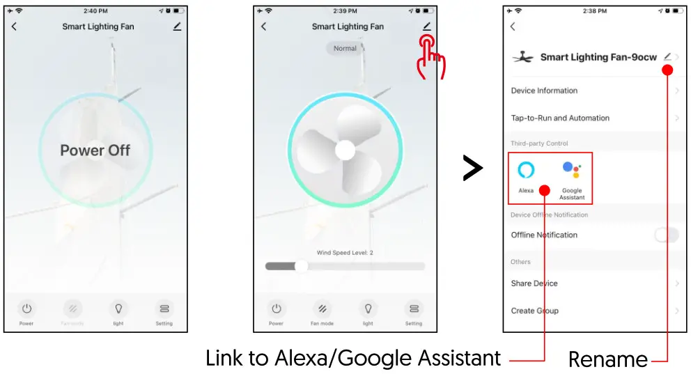
- App cPanel After the device be added successfully, you can control ceiling fan power on/off, wind speed level [level 1-6), fan mode[normal or nature), lamp on/off, and fan direction(forward or reverse). You also can tap L icon to the device attribute page to get more function configurations, like device rename, 3rd-party control, share device, create group, etc.

- How to works with Amazon Alexa/Google Assistant?
• Tap the “ ” icon of the smart ceiling fan main panel
• Tap the 3rd-party control Alexa or Google icon to be operated
• Sign in with your Amazon Alexa or Googe account
![]()
Now you can use your voice to control the smart ceiling fan:
| Functions | Alexa Commands |
| Fan On/Off | Alexa, turn <device name> on/o |
| Fan Speed | Alexa, set <device name> speed to 1/2/3/4/5/6 |
| Fan Mode | Alexa, set <device name> to nature/normal |
| Fan Direction | Alexa, set <device name> to forward/reverse |
| Light On/Off | Alexa, turn on/oe name> |
| Functions | Google Commands |
| Fan On/Off | Hey Google, turn <device name> on/o |
| Fan Speed | Hey Google, set <device name> speed to 1/2/3/4/5/6 |
| Fan Mode | Hey Google, set <device name> to nature/normal |
| Fan Direction | Hey Google, set <device name> to forward/reverse |
| Light On/Off | Hey Google, turn on/oe name> |
Need help?
![]()
https://www.youtube.com/channel/UCsGqB4IKW1NmZlK2mfBBAww https://www.tidio.com/talk/service_chatonline
]]>