![]()
INSTRUCTION MANUAL
CATALOG NUMBER
| BPP05WTB BPP06WTB BPP08WTB |
BPP08HWTB BPP10WTB BPP10HWTB |

Thank you for choosing BLACK+DECKER!
PLEASE READ BEFORE RETURNING THIS PRODUCT FOR ANY REASON.
If you have a question or experience a problem with your BLACK+DECKER purchase, go to www.blackanddecker.com/instantanswers
If you can’t find the answer or do not have access to the Internet, call 844-299-0879 from 10:30 a.m. to 6:30 p.m. EST Mon. – Fri. to speak with an agent. Please have the catalog number available when you call.
SAVE THIS MANUAL FOR FUTURE REFERENCE.
PRODUCT REGISTRATION
Thank you for purchasing our BLACK+DECKER product. This easy-to-use manual will guide you in getting the best use of your air conditioner.
Remember to record the model and serial numbers. They are on a label on the rear.
Staple your receipt in your manual.
You will need it to obtain a warranty service.
Model number
Serial number
Date of purchase
SAFETY INFORMATION
![]() DANGER – Immediate hazards which WILL result in severe personal injury or death
DANGER – Immediate hazards which WILL result in severe personal injury or death
![]() WARNING – Hazards or unsafe practices that COULD result in severe personal injury or death
WARNING – Hazards or unsafe practices that COULD result in severe personal injury or death
![]() CAUTION – Hazards or unsafe practices that COULD result in minor personal injury
CAUTION – Hazards or unsafe practices that COULD result in minor personal injury
IMPORTANT SAFETY INSTRUCTIONS
![]() WARNING
WARNING
When using electrical appliances, basic safety precautions should be followed, including the following
- To reduce the risk of injury, read this guide before using the appliance.
- The air conditioner must be connected to a proper electrical outlet with the correct electrical supply.
- Proper grounding must be ensured to reduce the risk of shock and fire. DO NOT CUT OR REMOVE THE GROUNDING PRONG. If you do not have a three-prong electric receptacle outlet in the wall, have a certified electrician install the proper receptacle. The wall receptacle MUST be properly grounded.
- Do not operate the air conditioner if power cord is frayed or otherwise damaged. Avoid using it if there are any cracks or abrasion damage along the length, plug connector or if the unit malfunctions or is damaged in any manner. Contact an authorized service technician for examination, repairs, or adjustments.
- DO NOT USE AN ADAPTER OR AN EXTENSION CORD.
- Do not block airflow around the air conditioner. The exhaust hose should be free of any obstructions.
- Always unplug the air conditioner before servicing it or moving it.
- Do not install or use the air conditioner in any area where the atmosphere contains combustible gases or where the atmosphere is oily or sulfurous. Avoid any chemicals coming in contact with your air conditioner.
- Do not place any object on the top of the unit.
- Never operate the air conditioner without filters in place.
- Do not use the air conditioner near a bathtub, shower, or washbasin.
- This appliance is not intended for use by persons (including children) with reduced physical sensory or mental capabilities or lack of experience & knowledge unless they have been given supervision or instruction concerning the use of the appliance by a person responsible for their safety.
- Children should be supervised to ensure that they do not play with the appliance.

- The air conditioner shall be installed in accordance with national wiring regulations.

HANDLING ALKALINE BATTERIES
![]() WARNING
WARNING
When handling alkaline batteries, basic safety precautions should be followed, including the following
- Should fluid from the battery accidentally gets into your eyes, there is a threat of loss of eyesight, do not rub them. Immediately rinse your eyes with clean tap water and then consult a physician immediately.
- Do not put the battery in a fire, expose it to heat, dismantle or modify it. If the insulation or safety valve is damaged, the battery may leak fluid, overheat or explode.
- Do not insert the battery with the poles reversed. Doing so may cause some abnormality or a short and the battery may leak fluid, overheat or explode.
- Keep the battery out of the reach of children. If the battery is swallowed, contact a physician immediately.
- If the alkali fluid gets in your mouth, rinse your mouth with water and contact a physician immediately.
- If the alkali fluid gets on your skin or clothes, it may burn your skin, thoroughly rinse the affected area with tap water.
- Do not mix new and old batteries or other makes of batteries. The different attributes may cause the battery to leak fluid, overheat or explode.
- This battery was not made to be recharged. Recharging this battery may damage the insulation or internal structure and may cause the battery to leak fluid, overheat or explode.
- Do not damage or remove the label on the exterior of the battery. Doing so may cause the battery to short, leak fluid, overheat or explode.
- Do not drop, throw or expose the battery to extreme impact. Doing so may cause the battery to leak fluid, overheat or explode.
- Do not alter the shape of the battery. If the insulation or safety valve is damaged, the battery may leak fluid, overheat or explode.
- Immediately remove batteries when they have lost all power. Leaving the batteries in the unit for a long time may cause the batteries to leak fluid, overheat or explode due to gas that is generated by the batteries.
- Remove the batteries from the unit when not using the unit for an extended period of time. The batteries may leak fluid, overheat or explode due to gas that is generated by the batteries.
- Do not apply solder directly to the batteries. The heat may cause the batteries to leak fluid, overheat or explode.
- Do not get the batteries wet. Doing so may cause the batteries to overheat
- Store batteries someplace out of direct sunlight where the temperature and humidity are not high. Not doing so may cause the batteries to leak fluid, overheat or explode. Also, it may cause the life and performance of the batteries to decline.
- Follow the regulations of the local government when disposing of these batteries.
- NEVER mix alkaline, standard (carbon-zinc), rechargeable (nickel-cadmium) batteries with this product.
SAVE THESE INSTRUCTIONS FOR HOUSEHOLD USE ONLY
GROUNDING INSTRUCTIONS
ELECTRICAL REQUIREMENTS
In the event of malfunction or breakdown, grounding provides a path of the least resistance for electric current to reduce the risk of electric shock.
The appliance must be connected to a cord having an equipment-grounding conductor and a grounding plug. The plug must be plugged into an appropriate outlet that is properly installed and grounded in accordance with all local codes and ordinances.
![]() DANGER – Improper connection of the equipment-grounding conductor can result in a risk of electric shock. The conductor with insulation having an outer surface that is green with or without yellow stripes is the equipment grounding conductor. If repair or replacement of the cord or plug is necessary, do not connect the equipment-grounding
DANGER – Improper connection of the equipment-grounding conductor can result in a risk of electric shock. The conductor with insulation having an outer surface that is green with or without yellow stripes is the equipment grounding conductor. If repair or replacement of the cord or plug is necessary, do not connect the equipment-grounding
conductor to a live terminal. Check with a qualified electrician or service person if the grounding instructions are not completely understood, or if in doubt as to whether the appliance is properly grounded. Do not modify the plug connected to the appliance – if it will not fit the outlet, have a proper outlet installed by a qualified electrician.
FOR GROUNDED, CORD-CONNECTED APPLIANCES RATED LESS THAN 15A AND INTENDED FOR USE ON A NOMINAL 120V SUPPLY CIRCUIT
The appliance is for use on a nominal 120V circuit and should be connected to a grounding outlet that looks like the one illustrated below. The use of a temporary adaptor is not recommended.

LCDI POWER CORD AND PLUG
This air conditioner is equipped with an LCDI (Leakage Current Detection and Interruption) power cord that is required by UL. This power supply cord contains state-of-the-art electronics that sense leakage current. If the cord is damaged and leakage occurs, power will be disconnected from the unit.
The test and reset buttons on the LCDI Plug are used to check if the plug is functioning properly.
WARNING: Test LCDI before each use.
To test the plug:
- Plug the power cord into a grounded 3-prong outlet.
- Press RESET (on some units a green light will turn on).
- Press the TEST button, the circuit should trip and cut all power to the air conditioner(on some units green light may turn off).
- Press the RESET button for use. You will hear a click and the A/C is ready for use.
- The power supply cord must be replaced if it fails to trip when the TEST button is pressed and the unit fails to reset.
NOTES:
- Do not use this device to turn the unit on or off.
- Always make sure the reset button is pushed in for the correct operation
 WARNING:
 - The power supply cord must be replaced if it fails to reset when either the test button is pushed, or it cannot be reset.
- If the power supply cord is damaged, it cannot be repaired.
- It must be replaced by one obtained from the product manufacturer.

![]() WARNING – RISK OF FIRE
WARNING – RISK OF FIRE
It is important the plug fits tightly into the wall outlet.
If the plug does not fit securely and appears loose, it should not be used.
Have a licensed electrician replace the receptacle.
SAFETY GUIDELINES
To prevent injury to the user or other people and property damage, the following instructions must be followed. Incorrect operation due to ignoring instructions may cause harm or damage.
| ALWAYS DO THIS | NEVER DO THIS | ENERGY SAVE |
| • Your air conditioner should be used in such a way that it is protected from moisture. e.g. condensation, splashed water, etc. Do not place or store your air conditioner where it can fall or be pulled into water or any other liquid. Unplug immediately. • Always transport your air conditioner in a vertical position and stand on a stable, level surface during use. • Turn off the product when not in use. • Always use the switch on the control panel to start or shut off the unit. • Always contact a qualified person to carry out repairs. If the supply cord is damaged it must be repaired by a qualified technician. • Keep an air path of at least 12 inches. all around the unit from walls, furniture, and curtains. • If the air conditioner is knocked over during use, turn off the unit and unplug from the power supply immediately. |
• Do not operate your air conditioner in a wet room such as a bathroom or laundry room. • Do not touch the unit with wet or damp hands or when barefoot. • Do not press the buttons on the control panel with anything other than your fingers. • Do not remove any fixed covers. Never use this appliance if it is not working properly, or if it has been dropped or damaged. • Never use the plug to start and stop the unit. • Do not cover or obstruct the inlet or outlet grilles. • Do not use hazardous chemicals to clean or come into contact with the unit. Do not use the unit in the presence of inflammable substances or vapor such as alcohol, insecticides, gasoline, etc. • Do not allow children to operate the unit unsupervised. • Do not use this product for functions other than those described in this instruction manual. |
• Use the unit in the recommended room size. 5,000 BTU up to 150 sq. ft. 6,000 TU up to 250 sq. ft. 8,000 BTU up to 350 sq. ft.10,000 BTU up to 450 sq. ft. • Locate the unit where furniture cannot obstruct the airflow. • Keep blinds/curtains drawn. • Keep the filters clean. • Keep doors and windows closed to keep cool air in and warm air out. |
OPERATING CONDITION
The air conditioner must be operated within the temperature range indicated below:
NOTE: · Unit performance may be affected when in use outside of these operating temperatures.
| MODE | ROOM TEMPERATURE |
| COOL | 64˚F (18˚C) ~ 95˚F (35˚C) |
| DEHUMIDIFY | 64˚F (18˚C) ~ 95˚F (35˚C) |
| HEAT (ELECTRICAL HEAT TYPE) | 45˚F (7°C) ~ 81˚F (27˚C) |
SET UP and USE
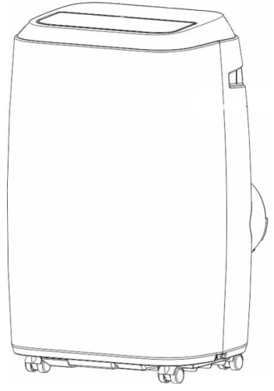
PARTS and FEATURES


SPECIFICATIONS
| BPP05WTB Unit dimensions (W x D x H): 17.32” x 14.05” x 27.16” BPP06WTB Unit dimensions (W x D x H): 17.32” x 14.05” x 27.16” BPP08WTB Unit dimensions (W x D x H): 17.32” x 14.05” x 27.16” BPP08HWTB Unit dimensions (W x D x H): 17.32” x 14.05” x 27.16” BPP10WTB Unit dimensions (W x D x H): 17.32” x 14.05” x 27.16” BPP10HWTB Unit dimensions (W x D x H): 17.32” x 14.05” x 27.16” Electric Requirements: 115V ~ 60Hz |
Unit Weight approx. 51.1 lbs. Unit Weight approx. 54.8 lbs. Unit Weight approx. 63.1 lbs. Unit Weight approx. 64.5 lbs. Unit Weight approx. 65.1 lbs. Unit Weight approx. 66.6 lbs. |
INSTALLATION GUIDE
LOCATION
- The air conditioner should be placed on a firm floor to minimize noise and vibration. For safe and secure positioning, place the unit on a smooth, level floor strong enough to support the unit.
- The unit has casters to aid placement, but they should be rolled on smooth, flat surfaces. Use caution when rolling on carpet surfaces. Do not attempt to roll the unit over objects.
- The unit must be placed within reach of a properly rated grounded socket.
- Never place any obstacles around the air inlet or outlet of the unit.
- Allow 12 inches to 36 inches of space from the wall with a window for efficient air-conditioning.
SUGGESTED TOOLS FOR WINDOW KIT INSTALLATION
- Screwdrivers (medium-size Phillips)
- Tape measure or ruler
- Knife or scissors
- Saw (In the event that the window kit needs to be cut down in size because the window is too narrow for direct installation)
WINDOW SLIDER KIT INSTALLATION
Your window slider kit has been designed to fit most standard “Vertical” and “Horizontal” window applications; however, it may be necessary for you to improvise/modify some aspects of the installation procedures for certain types of windows. Minimum and maximum window openings:
MAXIMUM : 47.2” (120 cm) MINIMUM : 27.5” (70 cm)
NOTE: · Adjust the length of the window slider kit according to the window width or height, and secure it with the provided locking screws.
NOTE: · If the window opening is less than 27.5” the minimum length of the window slider kit, cut the one with a hole in it short to fit for the window opening. Never cut out the hole in the window slider kit.

DOUBLE-HUNG SASH/SLIDING CASEMENT WINDOW INSTALLATION
- Cut the foam seal (adhesive type) to the proper length and attach it to the window sash.
- Attach the window slider kit to the window sash. Adjust the length of the window slider kit according to the width of the window. Shorten the adjustable window kit if the width of the window is less than 27.5”.
- Cut the foam seal (adhesive type) to the proper length and attach it to the top of the window.
- Close the window securely against the window slider kit.
- Secure the window slider kit to the window sash.
- Cut the foam seal to an appropriate length and seal the open gap between the top window frame and the outer window frame.

EXHAUST HOSE INSTALLATION
The air exhaust hose and hose inlet must be installed or removed from the portable air conditioner in accordance with the way it is being used:
COOL, DEHUMIDIFY, HEAT (Heat models BPP08HWTB and BPP10HWTB only:
The air exhaust hose and hose inlet should be connected to the portable air conditioner.
FAN: Air exhaust hose and hose inlet should be disconnected from the portable air conditioner.
- Connect the hose inlet to one end of the air exhaust hose. Push the hose inlet over the end of the hose, push in slightly and then start threading it on in a clockwise direction. (see Fig. 1)

- Connect the hose outlet to another end of the air exhaust hose. Push the hose outlet over the end of the hose, push in slightly and then start threading it on in a clockwise direction. (see Fig. 2)
- Align the tabs on the hose inlet into the slots over the air outlet, and insert and push down. (see Fig. 3)

- Insert the hose outlet into the window panel.
- Affix the hose outlet into the window slider kit and seal.
(Fig. 4 & 5)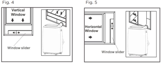


NOTE: The exhaust hose can be compressed or extended moderately, but it is desirable to keep the length to a minimum. Also, make sure that the hose does not have any sharp bends.

CONTROL PANEL

Pictures are for illustration purposes only. Your model may or may not have all the features.
OPERATING FROM THE CONTROL PANEL
The Control Panel enables you to manage all the main functions of the appliance, but to fully exploit its potential, you must use the remote control.
TURNING THE APPLIANCE ON
- Plug into the dedicated electrical outlet.
- Press the
 button until the appliance comes on. The last function active when it was turned off will appear.
* Never turn the air conditioner off by unplugging it from the outlet. Always press the button , then wait for a few minutes before unplugging. This allows the appliance to perform a cycle of checks to verify operation.
Note: Before pressing the Power On button make sure the condensate drain plug in the rear of the unit is securely in place to avoid any leaking. - Press the MODE button until the light corresponding to the required Mode lights up.

BPP08HWTB and
BPP10HWTB only
COOL MODE 
Ideal for hot weather when you need to cool the room.
To set the operation of the appliance correctly, press the + or – buttons until the desired temperature is displayed.
(See Fig. 7)

Then select the fan speed by pressing the Fan Speed Button until the light corresponding to the required fan speed lights up:


DEHUMIDIFY 
Press the “MODE” button until the “DEHUMIDIFY” indicator light comes on.
- Under this mode, you cannot select a fan speed or adjust the temperature.
The fan motor operates at LOW speed. - Keep window and door closed for the best dehumidifying effect.
- An exhaust hose attachment is not required to reduce humidity, however, it is recommended in very humid rooms so the warm air can be exhausted outside.
DEHUMIDIFICATION MODE
- It is recommended that the dehumidification drain and drain hose can be used for continuous drainage.
- FULL TANK –

The unit will have to be drained.

NOTE: Refer to the Water Drainage section.
FAN MODE 
- Press the “MODE” button until the “FAN” indicator light comes on.
- Press the speed button to select HIGH, MEDIUM, or LOW fan speed.
The temperature cannot be adjusted. - An exhaust hose attachment is not required in this mode.
HEAT MODE 
Press the “MODE” button until the “HEAT” indicator light comes on.
- Press the + or – buttons to select your desired room temperature.
The temperature can be set within a range of 61°F-88°F. - Press the speed button to select
HIGH, MEDIUM, or LOW fan speed.
NOTE: At the beginning of this mode, you may have to wait a few seconds before the appliance starts to give out hot air.
TIMER 
- To set the AUTO STOP timer. When the unit is ON, press the TIMER button.
- Press the + or – button to select the AUTO TIME in 1-hour increments, up to 24 hours. The LED Display will indicate the remaining time. Press the TIMER button again. The TIMER indicator light illuminates to show that the AUTO STOP program is initiated.
- To set the AUTO START timer. When the unit is OFF, press the TIMER button.
- Press the + or – button to select the AUTO TIME in 1-hour increments, up to 24 hours. The LED Display will indicate the remaining time. Press the TIMER button again. The TIMER indicator light illuminates to show that the AUTO START program is initiated.
- Pressing the POWER button or the TIMER button will cancel the AUTO START/STOP timed program and the timer indicator light will not be illuminated
SWING INDICATOR LIGHT 
When this light is illuminated, it indicates that the air swing is activated from the remote and the louvers will move up and down.
SLEEP INDICATOR LIGHT 
When this light is illuminated, it indicates that SLEEP has been activated from the remote control and that the temperature will gradually adjust.
OPERATING FROM THE REMOTE CONTROL
BATTERY INSTALLATION (BATTERIES NOT INCLUDED)
- Slide open the battery compartment cover.
- Insert 2 × “AAA” batteries as shown.
- Slide back the battery cover.

![]() CAUTION: Use only AAA or IEC R03 1.5V alkaline batteries. Remove the batteries if the remote is not used for a month or longer. Do not attempt to recharge the batteries. Both batteries should be replaced at the same time. Do not dispose of the batteries in a fire as the man explodes. Point the remote control at the receiver on the appliance. The remote control must be no more than 7 meters away from the appliance (without obstacles between the remote control and the receiver).
CAUTION: Use only AAA or IEC R03 1.5V alkaline batteries. Remove the batteries if the remote is not used for a month or longer. Do not attempt to recharge the batteries. Both batteries should be replaced at the same time. Do not dispose of the batteries in a fire as the man explodes. Point the remote control at the receiver on the appliance. The remote control must be no more than 7 meters away from the appliance (without obstacles between the remote control and the receiver).
The remote control must be handled with extreme care. Do not drop it or expose it to direct sunlight or sources of heat.

REMOTE CONTROL

POWER BUTTON: Press to turn ON or OFF
TIMER BUTTON: Used to set a delayed start or shut down downtime.
MODE BUTTON: Each time you press the button COOL, DEHUMIDIFY, FAN, HEAT (models BPP08HWTB and BPP10HWTB are selected)
˚C / ˚F SELECTOR BUTTON: Select Fahrenheit or Celsius.
INCREASE: Increase the temperature setting.
DECREASE: Decrease the temperature setting.
LED BUTTON: Illuminates the LED screen on the unit.
SWING BUTTON: Activates the air swing of the louvers.
FAN SPEED BUTTON: Used to select the HIGH, MED, or LOW Fan speed.
SLEEP BUTTON: Gradually adjusts the temperature.
| LED Display Indicators | |||
|
Cooling mode |  |
Fan speed |
 |
Dehumidify mode | |
Swing |
|
Fan mode |  |
Timer on |
 |
Heat mode Heat models BPPO8HWTB and BPP1OHWTB only |
 |
Time |
 |
Sleep | ||
 |
Display temp. or hours |
 |
Fahrenheit or Celsius. |
POWER BUTTON ![]()
- Press to Turn Air Conditioner ON or OFF. Press the LED button to illuminate the LED screen on the unit.


MODE BUTTON 
- Press the mode button to scroll through COOL


FAN

- The corresponding symbol will illuminate on the LED display to indicate which mode is selected.
COOL
- Select the target temperature 61˚F – 88˚F (16˚C – 31˚C) by pressing the + or – buttons until the desired temperature is displayed on the LED screen.
- Press the Fan Speed Button

DEHUMIDIFY
Ideal for reducing humidity.
- Keep window and door closed for the best dehumidifying effect.
- An exhaust hose attachment is not required to reduce humidity, however, it is recommended in very humid rooms so the warm air can be exhausted outside.
Draining in Dehumidify mode - It is recommended that the dehumidification drain and drain hose be used for continuous drainage.
- FULL TANK – When the water level reaches a predetermined level, the “full tank” indicator light goes on. The unit will have to be drained.
NOTE: Refer to the Water Drainage section. - In this mode, fan speed is selected automatically by the appliance and can not be set manually.
FAN
- Press the Fan Speed Button
HEAT
- Select the target temperature 61˚F – 88˚F (16˚C – 31˚C) by pressing the + or – buttons until the desired temperature is displayed on the LED screen.
- Press the speed button to select HIGH, MEDIUM, or LOW fan speed.
NOTE: At the beginning of this mode, you may have to wait a few seconds before the appliance starts to give out hot air.
SWING
- Press this button to activate the air swing of the louvers. Press it again to deactivate.
TIMER
- To set the AUTO STOP timer. When the unit is ON, press the TIMER button. The TIME ON/OFF symbol on the remote LCD display will blink.
- Press the + or – button to select the AUTO TIME in 1-hour increments, up to 24 hours. The Remote LCD Display will indicate the selected time. Press the TIMER button again to set the selected time. There will be a steady TIME ON/ OFF symbol on the remote LCD display and the TIMER indicator light will be illuminated on the control panel of the unit to show that the AUTO STOP program is initiated.
- To set the AUTO START timer. When the unit is OFF, press the TIMER button.
The TIME ON/OFF symbol on the remote LCD display will blink. - Press the + or – button to select the AUTO TIME in 1-hour increments, up to 24 hours. The Remote LCD Display will indicate the selected time. Press the TIMER button again to set the selected time. There will be a steady TIME ON/ OFF symbol on the remote LCD display and the TIMER indicator light will be illuminated on the control panel of the unit to show that the AUTO START program is initiated.
- Pressing the POWER button or the TIMER button will cancel the AUTO START/ STOP timed program and the timer indicator light will not be illuminated
SLEEP
- The SLEEP function gradually adjusts the temperature of the rooms to provide a comfortable environment. Press the SLEEP button to activate.
- In COOL mode, the temperature will increase 1°F after an hour and 2°F after 2 hours.
- In HEAT mode, the temperature will decrease 1°F after an hour and 2°F after 2 hours.
- To cancel this setting press the SLEEP button again.
°C / °F SELECTOR BUTTON
- When the appliance is powered on, press the °C / °F button, then you can select the unit of temperature from Fahrenheit or Celsius.

WATER DRAINAGE FOR COOLING AND HEAT MODES
This air conditioner is equipped with auto water evaporation so the water compartment would not typically fill in cooling or heating mode unless there is high humidity. Water drainage will generally only be required at the end of the season for these modes. (see START-END OF SEASON OPERATIONS).
NOTE: FULL TANK – When the water level reaches a predetermined level, the “full tank” indicator light located on the control panel of the unit goes on.
If an error code appears on the display screen on the control panel “E2” in COOL mode or “E4” in HEAT mode. The unit will have to be drained.
Intermittent Draining
- Unplug the unit from the power source. Carefully move the unit to a drain area over your basement floor or drip pan (not included). Remove the bottom drain cap.
- Let the water drain away and replace the drain cap. Restart the machine until the error codes E2 or E4 disappear. If the error repeats, call for service.

NOTE: Be sure to reinstall the bottom drain plug before using the unit.
Continuous Draining
- Unplug the unit from the power source. Remove the bottom drain cap. While doing this operation some residual water may spill so have a drip pan (not supplied) to collect the water.
- Connect the drain hose (supplied) as shown in the diagram. The water can be continuously drained through the hose into a floor drain or drip tray.
- Turn on the unit.

WAIT 3 MINUTES BEFORE RESUMING THE OPERATION
- After the unit has stopped, it cannot be restarted for 3 minutes. The operation will automatically restart after 3 minutes.
Continuous Draining for Dehumidification Mode
Unplug the unit from the power source.
Remove the drain cap located in the back center of the unit. While doing this operation some residual water may spill so have a drip pan (not supplied) to collect the water.
Connect the drain hose (supplied) as shown in the diagram. The water can be continuously drained through the hose into a floor drain or bucket.
Turn on the unit.

WAIT 3 MINUTES BEFORE RESUMING THE OPERATION
- After the unit has stopped, it cannot be restarted for 3 minutes. The operation will automatically restart after 3 minutes.
CLEANING and CARE
CLEANING
WARNING: Before cleaning or maintenance, turn the appliance off by pressing the ![]() button on the control panel or
button on the control panel or ![]() the button on the remote control. Unplug from the electrical outlet.
the button on the remote control. Unplug from the electrical outlet.
CLEANING THE CABINET
You should clean the appliance with a slightly damp cloth and then dry it with a dry cloth.
- Never saturate the air conditioner with water.
- Never use petrol, alcohol, or solvents to clean the appliance.
- Never spray insecticide liquids or similar near the air conditioner.
CLEANING THE FILTER
To keep your air conditioner working efficiently, you should clean the evaporator filter every week of operation.
The filter is housed in the intake grill.
Use a vacuum cleaner to remove dust accumulations from the filter.
If it is very dirty, immerse it in warm water and rinse a number of times.
The water should be lukewarm.
After washing, leave the filter to dry then re-insert the filter.

START-END OF SEASON OPERATIONS
START OF SEASON CHECKS
Make sure the power cable and plug are undamaged.
Follow the installation instructions precisely.
END OF SEASON OPERATIONS
See the Water Drainage section to make sure the air conditioner is completely drained of water.
Clean the filter and dry thoroughly before reinstalling.
TROUBLESHOOTING and WARRANTY
BEFORE YOU CALL FOR SERVICE
IF THE AIR CONDITIONER FAILS TO OPERATE:
A) Check to make sure that the air conditioner is plugged in securely. If it is not, remove the plug from the outlet, wait 10 seconds, and plug it in again securely.
B) Check for a blown circuit fuse or a tripped main circuit breaker. If these seem to be operating properly, test the outlet with another appliance.
WARNING
IF NONE OF THE ABOVE SOLVES THE PROBLEM, CONTACT A QUALIFIED TECHNICIAN. DO NOT TRY TO ADJUST OR REPAIR THE AIR CONDITIONER YOURSELF. Any person who is involved with working on or breaking into a refrigerant circuit should hold a currently valid certificate from industry accredited assessment authority, which authorizes their competence to handle refrigerants safely in accordance with an industry-recognized assessment specification.
WARNING
Do not use means to accelerate the defrosting process or to clean other than those recommended by the manufacturer.
WARNING
Servicing shall only be performed as recommended by the equipment manufacturer. Maintenance and repair requiring the assistance of other skilled personnel shall be carried out under the supervision of the person competent in the use of the flammable refrigerants.
CUSTOMER SERVICE
IMPORTANT
DO NOT RETURN THIS PRODUCT TO THE STORE
If you have a problem with this product, please contact the BLACK+DECKER Customer Satisfaction Center at 844-299-0879. DATED PROOF OF PURCHASE, MODEL #, AND SERIAL # REQUIRED FOR WARRANTY SERVICE
 |
 |
| Caution: Risk of fire/ flammable materials (Required for R32/R290 units only) | IMPORTANT NOTE: Read this manual carefully before installing or operating your new air conditioning unit. Make sure to save this manual for future reference. |
Troubleshoot your problem by using the chart below. If the air conditioner still does not work properly, contact BLACK+DECKER customer service center or the nearest
authorized service center. Customers must never troubleshoot internal components.
| TROUBLE | POSSIBLE CAUSE | POSSIBLE REMEDY |
| The unit does not start when pressing the ON/OFF button | A.Water full indicator light is on. LED display indicates “E2” in COOL mode or “E4” in HEAT mode. B.Room temperature is lower than set temperature (cooling mode) |
A.Drain the water B.Reset the temperature |
| Not cool enough | A.The windows or doors in the room are not closed B.There are heat sources inside the room C.Exhaust air duct is not connected or blocked D.Temperature setting is too high E.Air filter is blocked by dust F.The unit will take approx 3 minutes of operation before cooling occurs. |
A.Make sure all the windows and doors are closed B.Remove the heat sources if possible C.Connect the duct and make sure it can function properly D.Decrease the set temperature E.Clean the air filter F.A microprocessor control delays the compressor from operating until 3 mins have passed. |
| Noisy or vibration | A. The surface is not level or not flat enough | A. Place the unit on a flat, level surface if possible |
| The unit does not run and the water full indicator light is on. LED display indicates “E2” in COOL mode or “E4” in HEAT mode. |
A. The unit needs to be drained. | A. Refer to the water drainage section. |
| LED display “EO” , “El”, “E3” | A.EO – Room temperature sensor issue B.El- Condenser temperature sensor C.E3- Evaporator temperature sensor |
Contact the Customer Satisfaction Center for assistance with the error code. |
| The Remote is not working | A.Nothing Appears on the LED screen. B.The temperature and symbols appear on the LED screen but the selection cannot be changed. |
A.Press the LED button on the remote. If it does not illuminate, change the batteries. B.Make sure the remote is being pointed at the remote control receiver on the unit within 23 feet away and that there are no obstructions. |
LIMITED WARRANTY
Any repair, replacement, or warranty service, and all questions about this product should be directed to BLACK+DECKER at 844-299-0879 from the USA or Puerto Rico.
BLACK+DECKER warrants to the original purchaser that the product will be free from defects in material, parts, and workmanship for the period designated for this product. The warranty commences the day the product is purchased and covers up to a period of 1 year (12 months) for labor/1 year (12 months) for parts (manufacturing defects only).
BLACK+DECKER agrees that it will, at its option, replace the defective product with either a new or remanufactured unit equivalent to your original purchase during the warranty period. Exclusions: This warranty does not apply to the below:
- If the appearance or exterior of the product has been damaged or defaced, altered, or modified in design or construction.
- If the product’s original serial number has been altered or removed or cannot be readily determined.
- If there is damage due to a power line surge, user damage to the AC power cord or connection to an improper voltage source.
- If damage is due to general misuse, accidents, or acts of God.
- If repair attempts are done by unauthorized service agents, use of parts other than genuine parts or parts obtained from persons other than authorized service companies.
- On units that have been transferred from the original owner.
- On products that have been purchased as refurbished, like new, second-hand, in “As-Is” or “Final Sale” terms.
- To products used in a commercial or rental setting.
- To products used in settings other than ordinary household use or used other than in accordance with the provided instructions.
- To damages for service calls for improper installations.
- Transportation and shipping costs are associated with the replacement of the unit.
- Service calls to instruct you how to use your product.
- Service calls to repair or replace the house fuse, reset the circuit breaker or correct the wiring in the house.
REPAIR OR REPLACEMENT AS PROVIDED UNDER THIS WARRANTY IS THE EXCLUSIVE REMEDY OF THE CUSTOMER; BLACK+DECKER. SHALL NOT BE LIABLE FOR ANY INCIDENTAL OR CONSEQUENTIAL DAMAGES FOR BREACH OF ANY EXPRESS OR IMPLIED WARRANTY ON THIS PRODUCT, EXCEPT TO THE EXTENT PROHIBITED BY APPLICABLE LAW.
ANY IMPLIED WARRANTY OF MERCHANTABILITY OR FITNESS FOR A PARTICULAR PURPOSE ON THIS PRODUCT IS LIMITED TO THE DURATION OF THE WARRANTY.
Some states do not allow the exclusion or limitations of incidental or consequential damages, or limitations on how long the warranty lasts. In these cases, the above exclusions or limitations may not apply to you.
This warranty gives you specific legal rights and you may also have other rights which vary from state to state.
Obtaining Service: To obtain service, product literature, supplies, or accessories please call 844-299-0879 to create a ticket for exchange/repair.
Please make sure to provide the date of purchase, model number, and a brief description of the problem.
Our customer service representative will contact you or send detailed return instructions.
BLACK+DECKER does not warrant that the appliance will work properly in all environmental conditions, and makes no warranty and representation, either implied or expressed, with respect to the quality, performance, merchantability, or fitness for a particular purpose other than the purpose identified within this user’s manual. BLACK+DECKER has made every effort to ensure that this user’s manual is accurate and disclaims liability for any inaccuracies or omissions that may have occurred. Information in this user’s manual is subject to change without notice and does not represent a commitment on the part of BLACK+DECKER.
BLACK+DECKER reserves the right to make improvements to this user’s manual and/or to the products described in this user’s manual at any time without notice. If you find information in this manual that is incorrect, misleading, or incomplete, please contact us at 844-299-0879.
W Appliance Co.
1356 Broadway
New York, NY 10018
This device complies with part 15 of the FCC rules. Operation is subject to the following two conditions: 1) This device may not cause harmful interference, and 2) This device must accept any interference received, including interference that may cause undesired operation. This equipment has been tested and found to comply with the limits for a Class B digital device, pursuant to Part 15 of the FCC rules. These limits are designed to provide reasonable protection against harmful interference in a residential installation. This equipment generates, uses, and can radiate radio frequency energy and, if not installed and used in accordance with the instructions, may cause harmful interference to radio communications. However, there is no guarantee that the interference will not occur in a particular installation. Suppose this equipment does cause harmful interference to radio or television reception, which can be determined by turning the equipment off and on. In that case, the user is encouraged to try to correct the interference by one or more of the following measures: a) Reorient or relocate the receiving antenna. b) Increase the separation between the equipment and the receiver. c) Connect the equipment into an outlet different from that which the receiver is connected. d) Consult the dealer or an experienced radio/ TV technician for help.
BLACK & DECKER, BLACK+DECKER, the BLACK & DECKER and BLACK+DECKER logos and product names, and the orange and black color scheme are trademarks of The Black & Decker Corporation, used under license.
All rights reserved.
The product in this box may differ slightly from that pictured. Does not affect function. Not all accessories shown in photography are included in this package.
Imported by W Appliance, Inc., 1356 Broadway, New York, NY 10018
January 2021
Printed in China