CORSAIR RM650 Fully-Modular ATX Power Supply

CONGRATULATIONS ON THE PURCHASE OF YOUR
NEW CORSAIR RM SERIES ATX POWER SUPPLY!
CORSAIR RM Series fully modular power supplies deliver reliable 80 PLUS Gold efficient power toyour system.Please be sure to only use the screws, cables, and other hardware included in the box. Use of third-party hardware could result in damage to your power supply or your system and its components.
SAFETY AND PROTECTION
- Over-Voltage Protection (OVP)
Over-voltage protection for the 12V, 5V, and 3.3V DC outputs is required to comply with the ATX specification. OVP shuts down the PSU in the event that the DC outputs exceed a set level, determined by the PSU manufacturer. - Over-Current Protection (OCP)
OCP is featured on the 3.3V, 5V, and 12V rails. OCP ensures that the output of the DC voltage rails remains within safe operating limits. - Over-Temperature Protection (OTP)
OTP ensures that the PSU will shut down when the internal temperature reaches a set point. This is usually as a result of internal current overloading or a fan failure. - Short-Circuit Protection (SCP)
A short-circuit is defined as any output impedance of less than 0.1 ohms. Amongst other things, SCP ensures that the PSU shuts down should the 3.3V, 5V, and 12V rails short to any other rail, or to ground. It also ensures that no damage should occur to the unit, or your PC’s components in the event of a short.
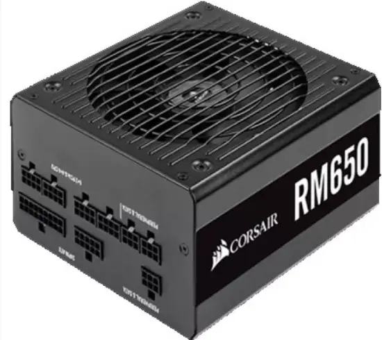
RM650 INCLUDED HARDWARE AND SPECIFICATIONS
Dimensions: 160mm(L) x 150mm(W) x 86mm(H)
Package contents: Power Supply, AC cable, DC cables, cable ties, mounting screws, safety leaflet
CORSAIR RM650 POWER TABLE
CORSAIR RM650 POWER SUPPLY EFFICIENCY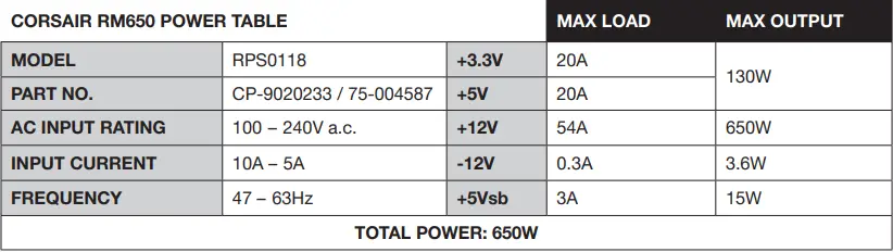
CORSAIR RM650 POWER SUPPLY FAN NOISE CURVE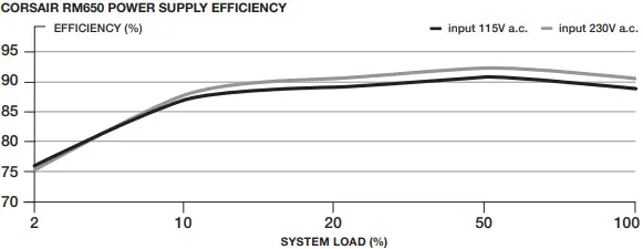
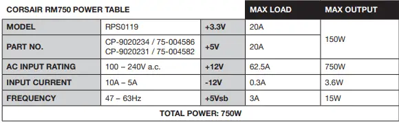
RM750 INCLUDED HARDWARE AND SPECIFICATIONS
Dimensions: 160mm(L) x 150mm(W) x 86mm(H)
Package contents: Power supply, AC cable, DC cables, cable ties, mounting screws, safety leaflet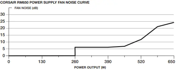
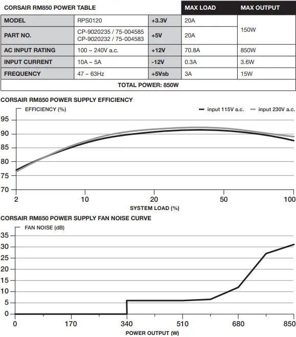
RM850 INCLUDED HARDWARE AND SPECIFICATIONS
CORSAIR RM SERIES CABLE INFORMATION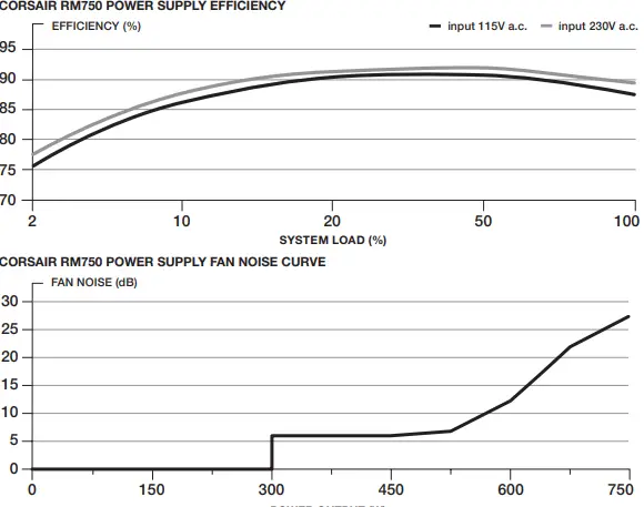
INSTALLING YOUR NEW RM SERIES POWER SUPPLY
Step 1: Removing Your existing PSU
WARNING! To ensure proper function, only use the DC cables included with your new PSU, unless your old cables are genuine CORSAIR cables of the same type. Please confirm your e xisting cables’ type before using them!
If you are building a new system, skip to Step 2:
- Disconnect the AC power cord from your wall outlet or UPS and from the existing power supply.
- Disconnect all the power cables from your video card, motherboard and all other peripherals.
- Follow the directions in your chassis manual and uninstall your existing PSU.
- 4. Proceed to Step 2.
Step 2: Installing the New Power Supply
- Make sure the power supply’s AC power cable is not connected.
- Follow the directions in your chassis manual and install the power supply with the screws provided.
- Connect the 24-pin (ATX) cable to the motherboard. Connect the 8-pin +12V (EPS12V) cable to the motherboard.
- If your motherboard has an eight-pin +12V socket, connect the eight-pin cable directly to your motherboard.
- If your motherboard has a four-pin socket, detach the four-pin from the eight-pin cable, and then plug this four-pin cable directly to your motherboard.
- Some motherboards will require a mix of 8+4 pins, use as many EPS12V cables as necessary and do not mistake them for PCIe cables.
- Connect the peripheral cables, PCI-Express cables, and SATA cables.
- Connect the SATA cables to your SATA SSD or hard drive’s power sockets.
- Connect the PCI-Express cables to the power sockets of your PCI-Express video cards if required.
- Connect the peripheral cables to any peripherals requiring a 4-pin connector.
- Make sure all the cables are tightly connected. Be sure to save any unused modular cables for future component additions.
- Connect the AC power cord to the power supply and turn it on by pushing the switch to the ON position (marked with “I”).