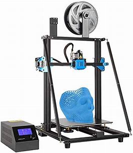
CR-10 V3 3D Printer 300x300x400mm with Meanwell Power Supply Support
View Fullscreen
CREALITY
3D Printer User Manual
( CR-10 V3)
V1 .0
Content El~
Dear Consumers, Thank you for choosing our products. For the best experience, please read the instructions before operating the Printer. Our teams will always be ready to render you the best services. Please contact us via the phone number or e-mail address provided at the end when you encounter any problem with the Printer. For a better experience in using our product, you can also learn how to use the Printer in the following ways: View the accompanied instructions and videos in the storage card. Visit our official website www.creality.com to find relevant software/hardware information, contactdetails and operation and maintenance instructions.
~11Jl(S<Jfrj’®::C:i!/llP : ~lt-J/fzJ’i’, ile/llfrU/:ll.=i!B<lF6/,onT/file/ll7J1′:, ii!l1ftEile/llLITTfff@li!IJi~~iJl,SJl’tl, #Ff!l:iilssi!/,SJl’tlB”it~’1’i!:!fi!lHl’o frU’®::C:i!im!,!.Sstt<U;Jtiinltmi!ifLmlB”l~~~otrile/lli1f¥’11:Jci1′:~iUH2,JcJl’J!i, illl:iilssi!/, S)l’tl~PP!imi!B”i~ii’i, ill!ffi~ttil’Ji!Hj~J.’~o n T1t,m~l!a:Htilif;$c~tttm S<Ji”-61,, 1mESoJ”Y-M”Y-~JJ’i’l’.Rl!Xiliii!ildemm: IIM/lile/lli!/,S)l: imoJ “y_ffl’¥ii1!-tPJ!’UUt§*ile/lli!/,SJlEl.t’lli)Jjo frU’®::C:i!!1llRJ :www.cxsw3d.com 1&’loJml’!MU/:ll::C:i!!1llRlsl-tM§*~~111′,lll<~7J’i”., iliii!lH’, ili&i~~~i/Li,!,o
Notes
Assemble the 3D Printer
Use the 3D Printer
f:fffl 3D HEP1′!1
Level the Heated Bed
i/al,:P:
Load Filament
~Jlq
Start Printing
:iHilJJEP
‘ ,——————————————————————————
l.Do not use the printer any way other than described herein in order to avoid personal injury or property damage.
‘
2.Do not place the printer near any heat source or flammable or explosive objects. We suggest placing it in a well-ventilated, low-dust environment.
3.Do not expose the printer to violent vibration or any unstable environment, as this may cause poor print quality.
4.Before using experimental or exotic filaments, we suggest using standard filaments such as ABS or PLA to calibrate and test the machine.
5.Do not use any other power cable except the one supplied. Always use a grounded three-prong power outlet.
6.Do not touch the nozzle or printing surface during operation as they may be hot. Keep hands away from machine while in use to avoid burns or personal injury.
7.Do not wear gloves or loose clothing when operating the printer. Such cloths may become tangled in the printers moving parts leading to burns, possible bodily injury, or printer darn age.
8.When cleaning debris from the printer hotend, always use the provided tools. Do not touch the nozzle directly when heated. This can cause personal injury.
9.Clean the printer frequently. Always turn the power off when cleaning, and wipe with a dry cloth to remove dust, adhered printing plastics or any other material off the frame, guide rails, or
wheels. Use glass cleaner or isopropyl alcohol to clean the print surface before every print for consistent results.
10.Children under 10 years of age should not use the printer without supervision.
11.This machine is equipped with a security protection mechanism. Do not manually move the nozzle and printing platform mechanism manually while booting up, otherwise the device will
automatically power off for safety.
12.Users shall comply with related nation and region’s laws, regulations and ethical codes where the equipment or produced prints by it is used, and users of our product shall not use
aforesaid products to print any end-use products,objects,parts or components or any other physical prints that violate the national or regional laws, regulations and ethical codes where herein
referred product and produced prints by it is located.
‘,—————————————————————————————————————————————————————-‘,
I
1, i.~?J.J’ii’ii’tfffoJ-fleffli.)/,Bjjq:i;~~:li’i’il&BkJJJ5!*1lem*tfl, lM:9’c@-5xBkJ~$lAs{95~;f
m1f”tvl~;
2, i.~mi~*tflm:’l!l’i’±~m,~~!to/J£!l!Gi’@ii?i5)j’11ili, i.~i~*tflm:’l!l’i’.±JfflJx, ~jj;jj'(,:J>~BkJifiipg;
3, J.~mi~HEPtflm:’l!l’i’±[email protected];fl:!l!Gtf;let{tlfff&)EilkJif±ipg, tfl~~ii;/J~f_;PfiilHEPtJlHfP,W:~;
4, ~i.x’.-fleffl1*1tf.¥~M, ~J:fcm-5xi±l*t’a>
tfl~v:;
s, J.~mi’±~*lif¥$-flem1t@f”£cg5)j~1-u~, l!-flem*tfl’1-tmtlkJcg5)jtf, cg5mm*~ffltE1ji’.±m~:1:ttJtxilkJ-=::J’LHag[;
6, i.~mi’±nEPtJlI{1’B1fflffi’RPJlj:Pjf/;~;l_&i!.r,R, mali:::±:Jl)l,i’@i).ifi.~195, @-6xAs{95~;
7, i.~mi’±Mk11’tfl~B11Fil.m-¥~!l!Gt!i~till, ~:J_llJ:ipJii!.Jl’!B{!j=xs_t Asl’l~f:J:m:,ox;g)ffiEHDtJJl!i’U{jj~;
8, tnEP’,c:.$F
&B1tUm
Plll:*BkJ#s).ifi.1’1l’HJJL~i~Plll:*…tilkJ~WlW’f;$, 51U~B1i.~mffifflffl-‘f.ffi’Rtf Pjjl:*, ~:J_llJ:i :±:ll)ll,~{jj;
9, ~1t0:f”£iUf’, )El1Jli’.±fficgilkJ·~;_1tT, ffl’f{1i’x1nEPtflfl&tfls5~55, Mzs:1x~>fD141:ii6il’9nEPM*”k~$tl…til’9~4ill;
l0,’iJc~i’.±105′! ~;!_ HkJ) Lil::, i!mi’.±59:~ )J,3_ll£_gtl’9ffi;5nfiem*tfl, W~’.@-6xAsf95~;
11,*tfli.~~~:@:1:iiUNJltU, i!mi’±:rHJl~~T-‘f.ii!.J'(:R:l!~ii!.JPJll:*&nEP:IJZi:l’tflfi.J, ‘i5’IJlU i.~ El ii!.J l’tli cg*tflf*tf’;
n -flemtf@Jj’tj’J.~~nEPf”£~i.~~,6Ji’1:±:1:tlJ&*El@§l*&:1:tlJ[R5!ft, 5!*)11,, ‘l’i§”1″~R,IJ:l~1i, F~-fleffl~P]f”£HEP~Jii.~~nEPf”£~i.~~,6/i’i’.±:l:tlJ&ffl@§j*,
:t:ttJIR5!ft~li::il’9fffoJF£!l!G!to/J11!=0
Introduction i9:”©f~*
11– – – 1 8
—————————————————————– ‘
1 Filament Holder~~&~~
1O Printing Platform jJEp:xp:;g
18 Filament Detector il/r~~;li!j
2 Control Box ~$!~
11 Pull Rod t.i’rlf
19 XE Transfer interface XE~Ji:l
3 LCD Screen fil.;f,lff
12 Base Frame ;j<Jl,~JEE~
20 X-axis Motor Xtib~i’/1,
4 Knob 11/fW.
13 Coupling ~
21 Z Limit Switch Z~llHi’L:ff:;1,c
5 USB per USB:li
14 Z-axis Motor(Z2) Z~~i’/l,(Z2)
22 Z-axisMotor(Zl) z~~i’/1,(Zl)
6 Storage Card Slot 1’¥~–lcl!i
15 Y Limit Switch Y~ll&1.i’r:ff:;1c
23 YZ Transfer interfac
YZ~Ji:l
7 Voltage Selection ~ffiJ!Ji’i~ 8 x Limit Switch X~~1.i’r:ff:;1c
16 Titan Extrusion Device~±§!!J’Hl:li’/1, 17 Y-axis Motor Ytib~m
24 Platform Connection i?.Pl<M!
25 Power Cable Connection ~;Jjiiffl.§l’,:f:;1,c
9 Nozzle Kit Pil!~ii’1~
‘-
2
¥*~~ Basic Parameters
Model I~”5
CR-10V3
Printing Size I .Bx~R’J
300*300*400mm
Molding Tech I .Bx~~* Nozzle Number I Pilt:~U;z~ Slice Thickness ItJJhfzi~ Nozzle Diameter I PjlP//HlH
FDM 1
0.lmm-0.4mm
Standard 0.4mm I~3.iil!c0.4mm
Precision I HfP*ii~ Fliament I HEPM11File Format ItJJh3Z’F-Ht:it Working Mode I HfPjj”:i:I’.; Slice Software I i:iJ*~tJJh~1!:!= Power Supply I Wt~’.~ffi Total Power I Wl~J:jJ$ Bed Temp I11.*~~5~~ Nozzle Temp I PjlPt/J~~5~~ Resume Print I iffi~gin
±0.lmm 1.75mm PLA STL/OBJ/AMF
Online or TF card offline I l!HJ,~TF-tfilWl,
Creality Slicer/Cura/Repetier-Host/Simplify3D Input! $#ii.J:AC115/230V 50/60Hz Outputl$tiil:±:l:DC 24V
350W ~100°( ~250°(
Yes I 3Zt~
Filament Detector I lffi11-Ml;DJ!
Yes I 3Zt~
Daul Z-Axis I xJ(Z$[iJ Auto Leveing I Elii.i.J~.l:JL
Yes I 3Zt~ No I 7f3Zt~
language Selection I 9:r~t)]~
English I ‘t1X
Operating System I ~~®J:*1-‘F~gfE Windows XP/Vista//7/8/10 MAC/Linux
Printing Speed IHEP~~
~180mm/s,Normall:i:E*~ 30-60mm/s
3
Parts List ~l’l~f!f:51~
I
e Pull Rod I Hrff x 1
~
C, Filament I ~;M x 1
–lil
0 Gantry Frame I ftl’l~ x 1
B lllll___ll · l!!jj__________
Spool & Nuts x 1
M~&:/,I~-jij
· Spool Holder x 1 M~
0 Base Frame I ~
x 1
8 Control Box I ~M
x 1
$ Tool list I~fil51~
M5X25 Bolt & Lock X 4
·
Washer
· M5X25 ffl~&sii!i!’mf”
Nozzle Cleaner x 1
—‘-· – – ~tt
:, >—C ·
(lti’._~ ~-
Cable Ties X 1 tL1i;
~:~;~;r Hex keys, Wrench x 1
(}
C, Tool Box I I~§ x 1
/ 7 — -“””-,,
(
‘
G) PTFE Tubing X 1
(spare part)
~m::lt~(ill-ilil
· Spade x 1
lfJJ
CY
El) Storage Card & X 1
Card Reader
l’¥fit-H
~-tf
~
G) M3xl8 Hexagon x4 Countersunk Head Screw
M3xl8i!sf.;J!l’JJJi::li<II~
~
G M5xl2 screws x 4 M5xl2llg/;
p
(P
· Diagonal Pliers x 1 ~m
& Material Detection x 1
I] ~~=::::o W Extension Cord
l#JiM~i!i!!!Jafil*!Ja
· L pull rod connector x 2 Ll!!11/i:fflllt14
~
.,. live bolts M6X35 X 4
W 5!Jtffl~M6X35
· MST nut x 4 M5Tl!J1ffljij
G, M6nut x4
M6ffljij
iwwD e
~ ~
-t!i) Po_wer Adapter x 1
Eg;J,l!Ji
· ScrewsM6X40 x 2
W’ t/*fflg/;M6X40
fli) Spare Limit switch x 1
ill-!llBIHi’Itf*
e
G M4T nut x 4 M4Tl!J1!1jij
G, Spare Parts x2
il!-llJPjPJo/lB14
~ b
~
limitswitchforZaxis x 1
W Z1l!illHi’Itf*
~
M4*16 cup head x 2
W’ screw
M4*161l!iltt:li<llH
~
LJ
G M5x30Hexagon Socket x 4 Button Head Screws M5x30[!s;’;;J!i’J’!”~:Ji<fflg!;
G M4x8 Hexagon Socket x 4 Button Head Screws M4x8i!s;’;;J!l’J’!”ll!il:li<II~
0 G Isolation Column x 4 ~il’itt
A Material Detection x 1 W Switch
l#Ji~~i!i!ltf*
4
Install the Gantry Frame ~~1.El’l~
Q Gantry Frame I ftfl~ x 1
O Base Frame I litt~ x 1
A MSX25 Bolt & Lock Washer x 4 W MSX25 ~tt:&s!f!’iiHtl:/t 5
Twist the coupling to raise the X axis to the position as picture shown.
t’rQJl!Hill~fleX~m_tft¥1J~D~rfi5TT{li.il:o
Pull Rod Installation G
0 ·?!· ·
PullRod x4
; ,. til:ff
‘
. . ‘
~
/ I
L pull rod connector x 2
Lll!ltftffii~i’t
~
~
· live bolts M6X35 X 4 W J!~!lttM6X35
~ ~
ScrewsM6X40 x 2
· ;!Jl,*ll~M6X40
M5xl2 screws X 4
E) M5xl2!1~
(P
· MST nut X 4 MST!l!l!IJll
~ff) -· M6nut x 4 M6lll;t
M5x30Hexagon Socket X 4 1
Button Head Screws M5x30P;J:;’-;1/l’!”lffll3isll~
· Isolation Column x 4 flilll!itt
——— ….. ,
I
6
Install the Rack and Filament Detector
~ft
l’ffi~~fd!!
‘,
· Spool Holder X 1
~
Q– — –·
Material Detection Bracket x 1 lffi~~;!i!!;!;~
Material Detection Switch x 1 lffi~~li!!f f *
u
M4x8 Hexagon Socket x 4 Button Head Screws M4x8Pl1’;!(l’l’mll~dilll~
~
M4Tnut x 4
M4Tl!!i!lll;,
M3x18 Hexagon x 4
Countersunk Head Screw M3x18PlMl1i)Ekt!!~
7
,, _______________________ ,,
I, ,-_ —— — ___ …, ——, ‘ I
~l
111..a.-….LI
I
I
Xt
,
~AIn~HZgsoldttl~ahIe.lHlHulmHimi~t,,wixt;;JkXshHwwLf;iutthlc§t,hheffhfl2ooflj)er/MaZo4d*a1t6hx(eji’ogs~lo*c-kJ~:~~;tz!ol$!loithrtt~lhl~!etr1fl1tef1lf~tfFipc:1cXo!;if!iYleIDo!f~thJ1e:ogaot,y w;th two M4·16 cop head sccew.
~ W
limit switch for Z axis Zld!~i.Uff~
x 1
Ci) M4·15 cup head screw x 2 M4·1s~tt~li!ln
8
Cable Connection i~*H~Mz
Connect the modules to the Controller as illustrated and power on. J1ill!ijf-11Hllffl.J/i’li¥1J~ltLlH, HH<tl)Jli:
Connect the Stepper Motors according to the yellow labels on the 6pin (4-wire) side 11,’!&6pin (4;Jl) li .tli’1M/£mjf-J!;<, Connect the Limit Switches according to the yellow labels on the 3pin (2-wire) side J1iW.l3pin (2;Ji) l li .tli’fM,!mj-J~u:H*
Connect the aviation connectors to the ports with corresponding pins J/i’!U1@ttl’l9:a<JM”2’llf~
dJ
& Material Detection x 1 W Extension Cord
IIJi~~;romQ;*!Ji
1 ~®P · PowerAdapter x 1 W <tJli!Ji
i– ——-i
0
I
I
o
I
I
I
I
I I
Zl I I
!§i
~ 1_ – – – – – – – – … ——·
Caution
e Select the correct input voltage to match your local mains (115/230V)
e Damage can occur If voltage is set incorrectly.
e connect the power cord and turn the power switch to 1 to turn it on.
e Do not connect or disconnect the cables when the machine is powered on.
e llUcfiEfflla<Jltl.>–<llEiiJ~[!!;io/Sla’J:211:±t!!<tllm (115/230V)
· ~ li’1f9:-E,
mll!l~~.6J!m~.
e l!i’li’1llm~#~’1llmlH*~~,~~mHm.
e §m§~<tl~. ~~l!i’li~~Hl!i’li~.
,,— —- —————-,’
I
I
I
~
: – -, – – – – – – – :
0
,
Z2
I
1_ – – – – – – – –
,
I
I ,., ..·
I O .———, I
VI z ~—
9
Bed Leveling iJal’fI’fii:l-
Prepare -Auto Home (Waiting for the nozzle to move to the left/front of the platform) -Prepare-Disable Steppers(Close stepper drive, release motor)
,itm-@J!Jli:,~ (~1~DPiD!il’~ivltUIJii’l’~ilu15) -,itm-*lltv~~l&ivl (ffb”)(~;jf],)
Info :::creen
~ ~ Pr I nt from TF
Ch-:1n;ie TF c =1rd
:t +
..
f1a,n
1
Mol,ie ax Is
+
– ~ – – – – – – – Set home offsets
..
D1s-:1ble stepper.;.
Info sct-een
~ ~
Pr In+. frc,m TF
Ch :in ~e TF c-:1rd
:t
..
fJa In Mol.Je ax Is
1
+
Auto home
+
Set h,:irne c,ff sets
D1.:-able steppers
f-Afif@_§_Wr_ ni _ _ _ _1·
~
L::1t191139e
-..
;il;-$.
·
..
..
ffi@. W.mi
~ ~
L::1t191J:1~e
;il;-$.
1 ..
-+
·
10
Move the nozzle the front/left leveling screw and adjust the platform height by turning the knob underneath (The thickness of a piece of A4 paper).
Use a piece of A4 paper (standard printer paper) to assist with the adjustment, making sure that the nozzle lightly scratches the paper. Complete the adjustment of the screw on all 4 corners.Repeat above steps 1-2 times if necessary.Keep adjusting until there is slight resistance on the A4 paper from the nozzle.
* ~iQJP]allJlj~~~..tJJllt-.tili:otl’iQJ~~, l}.Ji,tJ£P’J’~P]allJlj1l’.=~5li’TliilUHW,!;~;J;I;~, faJ~eJ<Jt,JO.lmm (-lAA4;E;a<J~J!t) o
~ff]j,JJ.;ffij,E!j-lJxM;MiU;/Jl}.J’J’>1l’.P]aPllilJUH~~t£A4;JUF~tUlao-(jx;;:’11,pJ/;11!l1’lt!R.i..tif,J’J’~~a<Jif,Ji,01′ f!Jil}.J~]jjilJ tt!:i’LiQJM;El;Bsl~~~~JIJ § PJallJlj a<J~11&:mtti0
,-
‘
, ————————————,
I
,, ____________________________________ , I
‘——————————————–‘
– -r!
· @
The nozzle is too far away from the platform, so the
-~ consumables can not adhere to the platform. £ OJID/liili’l’B;is;z, ;.~,c5’1a:r.l~tt’l’BLo
2=
2=
0
Filament are extruded evenly,just sticking on the platform.
;.tti/Hll!:,l’a, ~!Jzl’911tt’l’B Lo
2=
2=
CD
The nozzle is too close to the platform, and the filament are
not extruded enough, even scraping the platform.
OloJll/l(F!’B;!s;l!i,;.~mtll’flE,llEejW.:f’l’Bo
11
Preheating
r!M&
Method 1
I nf,:i screen
~ ~ Pr Int fr om TF Cf ,ang’:’ TF card
:t
..
Auto hoMe Set hc,rne c,ff:= et s
D 1.:-able :::tepFers
-t
Pt ehe3+_ Fl.A
-t
Pt ehe 3+_ ABS
+
Method 2
Info :::cre’:’n Prepare ~
~ Pr I t1+. from TF
:t
-t
..
Ha 1n
M~ -u–+-,-o-,-,-
t
FI l 3rnent
-t
-t
Store sett I t1~s
Control
t
B~ -~–d-:- – – – – – – – 0
..
Nozzle:
200
Fan .:,peed:
0
Preheat PLA conf
+
r[@.;al.rni
:i:*
~
L:1r,911d=”=’
~sjl.
..1
·
+
·
1[!:ll.;al.rni
i* l:i:m1J
….. .,…….
~sjl.
..1
· ·
…
·
..
0~11/!’::
200
12
When you wait for the temperature to rise, hang the filament over the Filament Holder.
31~W1~;Jll’i!Jt_trt-st ~nt,Hittl¥3t~_to
For smoother printing, the end of the filament should be placed as shown above. Y;J7Jll!ii~Ujt,ox:/JEP, ff;t;tB{)*yi/ii{n:ii@:PDl!l.olimo
i~ ·A
I
13
Load Filament “&*’1-
when the current temperature hits the target temperature, Pass the filament through the filament sensor, press the extrusion spring and feed in the filaments to the nozzle, and then keep await until you see the liquid filament comes out of the nozzle.
~mr;gJJ:JisiU 13 t~;.!i!.JJ:111, :mnM~i1Jlli~~;Dltl, ~ttmtilm~ii, :mnMtiliAffitilmJJ,JL~~lli!!DlfiL’li, ~fliUVmlil~!HmM5JiltilllP~ff-nMB ~ilt!liiG/Jxo
Tips: How to Replace the Filament? 1,Cutting filament near the Extruder and slowly feed new filament until they are fed into the new filament. 2, Withdrawing the filament quickly and feeding the new !aliment after nozzle preheated and filament pushed a little forward. Tips:Ji[JfoJ~jj!J,tW :t;;!-, ff:li!lffl1H:l:ltll~~~~;/Jgl!Ji, 11f:1Ji~tttlilll<J, Ei:llmttllllll<J-lllfl’il!t,J.Lt. :n1t=,fli11.IPllll’iFc, 1~~ttttiluJ’iJ1!-~Fc, ffil!Jl!it:l:l~tt, 1~ffi~ttzJo
I I I
14
Start Printing fHBHEP
Custom RepRap Information
RopRaomadries con bo,.s t ~ -or,, sohofa:,oo con ‘8t )Wl””‘1’ottrQ< ~ eue to re·e’Wthea,t,,jt cmilebefcre rt.ffir,Jton,curmchr,, If :,oolkii a <»f.Ut prc. . tor:,w,macrno addod thonrM<ei>1″‘-‘!!on ~
g~~:~s rw,_..,.1ne1, :,oo
O CR-=
Macm<l-“h X lrrm)
O cR-JO<O,l:R-30<0 O CR-400
0 CR-5ffiJ
O c·-:;cw _
M>cmii<loap(t, Y(mm ) Nozrle size (mm)
== I I CA-10V3
~
~
O CR-mm Q cR-l c.’O’-lOS
Q cR-lffi P!O
><oatodbod
Bed c ert<
i,0 , 0.O(RoS
t cd )
O cR-10&1
Q cR-lO S!5 O en
Oc=
Oc= –
O Erm-1 0 Erd9-,,.._-3 1
0 Er<laf-5
0 00..(E,:R~
·-
CrHlity Slicer_l.2.1msi
>>
( reality Slicer
3. Select langue your machine
Next
Selct
Next
Finsh.
1. Double click to install the software. Ig.::j;!,~14 2, Double click to open the software. Ifflf~14
Hli t l . aoJtJ -H’Ullt,/il’l.l i i.!i. 4’oltJ iclc lll f’: B28′.Dl!i
l l if; fflTWf:t t l ‘ l l l i l l l : ~ : l l : # J t c·t::tw:
–
~
~ ~ M J.:i fMJffi a ! !
t~~
O cR-5 O CR-~ 0 CR-:mo
Q CR-DIO/CR-DIOS
O c·-<040 Oc·-=
“1Mftn, lll tJl!~
IH:lH9tl>il.b”Jiti
lli:liTIJ:A’!Mt;J,,,…, or~· l!il#
fliiM
=fr,i;-,oval
~
~
Q cR-9:BJ
li!lllilttf
~
Q CR-lOrti Q CR-10,’at-lOS O cR-1.WPto
U l ll!jljJ!,!t
I ll’&~<‘.· (0JJ)] I ___io i!fl i!IR<£itoj,;)
O CR-10 5<
0 CR-10S5
O c·-·
a,~
O c~ Pro
0 Erdef-l 0 Erdl,-, . -.:JP<o Q Erdar-5
o ,rn1turnt1u ·~
® Bii:!<:11.a
lf Z~ /ltW/1’11.1:&.-i
ilWfi’M·XsaJ!I( 11:ll:IIU:.lt!llitl l : 0
3.-f1!<;~Jl’Eig
Next ~fxst/i!
tJL~ Next Finsh,
i1;J;xiSt:il.
15
>>
,_
4.0pen the software :fl~J/;!ICtn}’-
Load
Selct
the file Wait
Load (~IIJDzf’i’) Jltmxf’I
–
for slicing to finish
Start Printing
:rHtnm
>>
5.Generate G-code, and save the geode file to storage card.
~PX G ft~ 1JiH
6.lnsert the storage card Print Select the file to be printed.
fE!j) fil”F
Jg;:'”filEW.
lz;:fE3~
~nEP:st14
1r 1t _ , r …. ,~r,
1
M-:11n
:t
-r ‘=’F ::at.=1,-ttt,-l
~
—
Ft-I -t -t t — fl Tf
–
. ·
· >>
,.
ORefresh
Rabb I t . 9c,Jde test .geode
ffi”@.Wjjjj
t
.3::;j!;!ajl.
f
;jf~
l’i’ffi!J
L-:1r1~1ia-1….
;j!;!ajl.
+
+ +
+
>>
l’JRefre:::h
~ ~
File names must be Latin letters or numbers, not Chinese
characters or other special symbols
J :st1H5 ~~t.JLT~~li!G~~. ;i;:,m~5:ll~li!G:let1-t!J~?!i<N”5
Notes: For details on the software instructions, please refer to the slicing software manual in the memory card!
;,l.!llt~~: ~14-fiefflJ.Jl.a.llWffl, i.!!ii!fl’fil”””Fpgt:JJF”~14-fieffl-¥Jlfr !
16
Circuit Wiring
~ H
X axis motor
X’lil~l/1
o[
t!l ~ti]
~il
~I
G: uEnJ~nG: EJ
!Cl .. 11:1 . .
E2 axis motor E2′,l~il
.. J[: -]
ti]
Iii
tIii!l9″··M~ t!Iiil
ti]
i
G: E]
E] [:]m E] 00
H~U IJ ~uua I ~nun
0
Power input
~;!ili!JA
17
Heating pipe1
1mmtt 1
Storage Card
8’11if-Nl’i
Micro USB Port Micro USB ti
EXP1/12864 Screen interface EXP1/12884 }}/:l!Wm
EXP2/12864 Screen interface EXP2/12864
m1;rna:1
Y Limit switch
Yi!limi!z
Z Limit switch
Z’lilmi!z
Reserved port liilOO!lH:l
Reserved port
m1mm
BL-Touch Reserved port BL-Touch jjiji1iJjl[Q
Trouble-shooting
End
TF card File name
1, Erase t he TF card 2, Format the TF card 3, Replace the TF card
1. Rename the file wi th alphabet and numbers
Sl i ce
1. Move the model and rcst.’.lrt the slicing
> – – – – – 2, Restore the model with software
limit sw i tch
1. Reconnect the cables 2, Check via the replacement method
1. Reconnect the cables 2, Check vi a the replacement method
hot bed
1. Reconnect the cables
Thermistor
1. Reconnect the cables
Heat pipe
L Reconnect the cables
Thermistor
Slice/ T im i n g belt
Coupl ing
1. Reconnect the cables
1, Restart the slicing 2, Adjust the tension of the synchronous
belt
I, Fasten the coupling
Other Filament E stepper
I , Cl ean t he f i lament 2, Replace f i lament
l, Reconnect the cables 2, Check via. the replacement method
Resolved daused l contact for roplacnent The fault cannot be identified, r:ont1u:t to reso lved
18
1, jfJ;l!UJlt 2. lilitftUJlt 3. if~UJlt
1. ~iJJ!llllili:l!IJHU/rtJJit 2. ill!l!l!J!i:~f’f!J!i:!lll!
~-1:
~-_ 1:~ 8:fl :t-~ :- :-:-:-:-~
~ b · ·—-~-~-=-:-7:-:
~
~
~
<B>ll’c i”l
~ -~: , ~:.
1. lii!’1!lll 1. lii!’1!lll
~—–,
IJJftlf”l$’ill
t
–
–
–
–
~ _
_
_ 2_.
1.liffilJJ;t _iJ_.!l!,_! f_o”l _,$_’ill_l’·_’!_ i
_
_ ~
1. i'<liUt~.1<iili!l.liE 2. if~fl:~
E’1!!Ji.
, . lli:i!’1!lll 2. /!lM~i~!!H!’
19
Due to the differences between different machine models, the physical objects and the final images can differ.The final explanation rights shall be reserved by Shenzhen Creality 3D Technology Co., Ltd. ~4ij~t/lll!!=f151,:ll;!lm-‘alfiliiJ/JglJJili~J”F, illl>:ll;!lm;is)l, Ji,~ffillm:J;*tjll”$frl1fl=§!l’fl!ill!l.0a’J/ilill o
SHENZHEN CREALITY 3D TECHNOLOGY CO.,LTD. 11 F & Room 1201,Block 3,JinChengYuan,Tongsheng Community,
Dalang,Longhua District,Shenzhen,China,518109 Oflicial Website: www.creality.com Tel: +86 755-8523 4565 E-mail: [email protected] [email protected]
0’a’Jl»lil~: www.cxsw3d.com ~~%-J:MJl: 400 6133 882
0755-8523 4565

