DEWALT DW735 Portable Thickness Planer

DEWALT DW735 Portable Thickness Planer
DW735
13″ (325 mm) Heavy-Duty Portable Thickness Planer
If you have questions or comments, contact us.
1-800-4-D E WALT
Definitions: Safety Guidelines
The definitions below describe the level of severity for each signal word. Please read the manual and pay attention to these symbols.
 DANGER: Indicates an imminently hazardous situation which, if not avoided, will result in death or serious injury.
WARNING: Indicates a potentially hazardous situation which, if not avoided, could result in death or serious injury.
CAUTION: Indicates a potentially hazardous situation which, if not avoided, may result in minor or moderate injury.
NOTICE: Indicates a practice not related to personal injury which, if not avoided, may result in property damage.
IF YOU HAVE ANY QUESTIONS OR COMMENTS ABOUT THIS OR ANY D E WALT TOOL, CALL US TOLL FREE AT: 1-800-4-D E WALT (1-800-433-9258).
WARNING: To reduce the risk of injury, read the instruction manual.
SAVE THESE INSTRUCTIONS
Important Safety Instructions for All Tools
WARNING: For your own safety, read the instruction manual before operating the planer. Failure to heed these warnings may result in personal injury and serious damage to the planer. When servicing this tool, use only identical replacement parts. Have damaged cords replaced by an authorized service center.
DOUBLE INSULATION
Double insulated tools are constructed throughout with two separate layers of electrical insulation or one double thickness of insulation between you and the tool’s electrical system. Tools built with this insulation system are not intended to be grounded. As a result, your tool is equipped with a two prong plug which permits you to use extension cords without concern for maintaining a ground connection.
NOTE: Double insulation does not take the place of normal safety precautions when operating this tool. The insulation system is for added protection against injury resulting from a possible electrical insulation failure within the tool.
POLARIZED PLUGS
To reduce the risk of electric shock, this equipment has a polarized plug (one blade is wider than the other). This plug will fit in a polarized outlet only one way. If the plug does not fit fully into the outlet, reverse the plug. If it still does not fit, contact a qualified electrician to install the proper outlet. Do not change the plug in any way.
WARNING: When using electric tools, basic safety precautions should always be followed to reduce the risk of fire, electric shock, and personal injury, including the following:
General Safety Instructions
- KEEP GUARDS IN PLACE and in working order.
- REMOVE ADJUSTING KEYS AND WRENCHES. Form habit of checking to see that keys and adjusting wrenches are removed from tool before turning it on.
- KEEP WORK AREA CLEAN. Cluttered areas and benches invite injuries.
- DON’T USE IN DANGEROUS ENVIRONMENT. Don’t use power tools in damp or wet locations, or expose them to rain. Keep work area well lighted. Always operate tool in a well-ventilated area free of combustible materials, gasoline or solvent vapors. If sparks come in contact with flammable vapors, they may ignite, causing fire or explosion.
- KEEP CHILDREN AWAY. All visitors should be kept safe distance from work area.
- MAKE WORKSHOP KID PROOF with padlocks, master switches, or by removing starter keys.
- DON’T FORCE TOOL. It will do the job better and safer at the rate for which it was designed.
- USE RIGHT TOOL. Don’t force tool or attachment to do a job for which it was not designed.
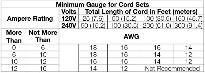
- USE PROPER EXTENSION CORD. Make sure your extension cord is in good condition. When using an extension cord, be sure to use one heavy enough to carry the current your product will draw. An undersized cord will cause a drop in line voltage resulting in overheating and loss of power. The following table shows the correct size to use depending on cord length and nameplate ampere rating. If in doubt, use the next heavier gauge. The smaller the gauge number, the heavier the cord. When operating a power tool outside, use an outdoor extension cord marked “W-A” or “W.” These cords are rated for outdoor use and reduce the risk of electric shock.
- WEAR PROPER APPAREL. Do not wear loose clothing, gloves, neckties, rings, bracelets, or other jewelry which may get caught in moving parts. Nonslip footwear is recommended. Wear protective hair covering to contain long hair. Air vents often cover moving parts and should also be avoided.
- ALWAYS USE SAFETY GLASSES. Also use face or dust mask if cutting operation is dusty. Everyday eyeglasses only have impact resistant lenses, they are not safety glasses.
- ACTUATING TOOL MAY RESULT IN FLYING DEBRIS, COLLATION MATERIAL, OR DUST WHICH COULD HARM OPERATOR’S EYES. The operator and all those persons in the general area should wear safety glasses with permanently attached side shields. Approved safety glasses are imprinted with the characters “Z87.1”. It is the employer’s responsibility to enforce the use of eye protection equipment by the tool operator and other people in the work area.
- SECURE WORK. Use of clamps or a vise to hold work when practical. It’s safer than using your hands and it frees both hands to operate tool.
- DON’T OVERREACH. Keep proper footing and balance at all times.
- MAINTAIN TOOLS WITH CARE. Keep tools sharp and clean for best and safest performance. Follow instructions for lubricating and changing accessories.
- DISCONNECT TOOLS before servicing; when changing accessories, such as blades, bits, cutters, and the like.
- REDUCE THE RISK OF UNINTENTIONAL STARTING. Make sure switch is in off position before plugging in.
- USE RECOMMENDED ACCESSORIES. Consult the instruction manual for recommended accessories. The use of improper accessories may cause risk of injury to persons.
- NEVER STAND ON TOOL. Serious injury could occur if the tool is tipped or if the cutting tool is unintentionally contacted.
- CHECK DAMAGED PARTS. Before further use of the tool, a guard or other part that is damaged should be carefully checked to determine that it will operate properly and perform its intended function—check for alignment of moving parts, binding of moving parts, breakage of parts, mounting, and any other conditions that may affect its operation. A guard or other part that is damaged should be properly repaired or replaced.
- DIRECTION OF FEED. Feed work into planer according to direction of feed arrows on top of the unit.
- NEVER LEAVE TOOL RUNNING UNATTENDED. TURN POWER OFF. Don’t leave tool until it comes to a complete stop.
Additional Specific Safety Rules for Planers
- To reduce the risk of injury, user must read and understand instruction manual before operating planer.
- Always wear eye protection and dust mask if necessary.
- Keep hands away from the underside of the cutter head carriage.
- Never clear clogs, make cutter knife replacement, or any other repairs/adjustments with unit plugged in.
- Make certain that the switch is in the OFF position before connecting plug to a power source.
- Be sure that the cutter knives are mounted as described in the instruction manual and check that all bolts are firmly tightened before connecting unit to power source.
- To avoid injury, never rotate the cutter block directly with your hands.
- Keep guards in place and in good working order.
- Stay alert—never operate the unit when tired or under the influence of drugs, alcohol, or medication.
- Do not use in dangerous environments. Do not use near flammable substances, in damp or wet locations, or expose to rain.
- Never plane material which is shorter than 12″ (304.8 mm).
- Exhaust chute: remove shavings with brush or vacuum after power has been shut off and cutter head has stopped rotating.
- ALWAYS LOCATE PLANER WITH PROPER CLEARANCE ON THE OUTFEED SIDE of the unit to prevent pinching or binding of the workpiece against any obstacle.
- Clean out your tool often, especially after heavy use. Dust and grit containing metal particles often accumulate on interior surfaces and could create a risk of serious injury, electric shock or electrocution. ALWAYS WEAR SAFETY GLASSES.
WARNING: For your own safety, it is recommended that two people carry this machine or serious injury could result.
WARNING: Always wear proper personal hearing protection that conforms to ANSI S12.6 (S3.19) during use. Under some conditions and duration of use, noise from this product may contribute to hearing loss.
WARNING: Some dust created by power sanding, sawing, grinding, drilling, and other construction activities contains chemicals known to the State of California to cause cancer, birth defects or other reproductive harm. Some examples of these chemicals are:
- lead from lead-based paints,
- crystalline silica from bricks and cement and other masonry products, and
- arsenic and chromium from chemically-treated lumber.
Your risk from these exposures varies, depending on how often you do this type of work. To reduce your exposure to these chemicals: work in a well ventilated area, and work with approved safety equipment, such as those dust masks that are specially designed to filter out microscopic particles.
- Avoid prolonged contact with dust from power sanding, sawing, grinding, drilling, and other construction activities. Wear protective clothing and wash exposed areas with soap and water. Allowing dust to get into your mouth, eyes, or lay on the skin may promote absorption of harmful chemicals.
WARNING: A dust mask or respirator should be worn by all persons entering the work area. The filter should be replaced daily or whenever the wearer has difficulty breathing. See your local hardware store for the proper NIOSH/OSHA approved dust mask.
- The label on your tool may include the following symbols. The symbols and their definitions are as follows:
Specifications
Input ______________ 120 V AC , 15 Amp
No load speed _______ 10,000 RPM
Feed speed __________ 14 ft. (4.3 m) per minute or 26 ft. (7,9 m) per minute
Planing height ________Maximum 6″ (152 mm), Minimum 1/8″ (3 mm)
Planing width ________ Maximum 13″ (325 mm)
Planing depth ________ Maximum 1/8″ (3 mm) (for boards 6″ (152 mm) wide or less)
Electrical Connection
Be sure your power supply agrees with the nameplate marking. Volts, 50/60 Hz or “AC only” means your planer must be operated only with alternating current and never with direct current. Voltage decrease of more than 10% will cause loss of power and overheating. All D E WALT tools are factory tested, if this tool does not operate, check the power supply.
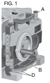
Transporting the Planer (Fig. 1)
WARNING: For your own safety, it is recommended that two people carry this machine or serious injury could result.
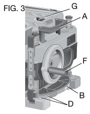
When moving your planer, carry it either by the side carrying handles (A) or by the handles at the base of the planer (B).
Bench Mounting
To facilitate bench mounting, two different sized holes (D) are provided on the four corners of your planer. If mounting the planer with bolts, use the larger holes. If mounting the planer with nails or screws, use the smaller holes. It is not necessary to use both sets of holes. Always mount your planer firmly to prevent movement. To enhance the tool’s portability, it can be mounted to a piece of 1/2″ (12.7 mm) or thicker plywood which can then be clamped to your work support or moved to other job sites and reclamped.
NOTE: If you elect to mount your planer onto a piece of plywood, make sure that the mounting screws don’t protrude from the bottom of the wood. The plywood must sit flush on the work support.
CAUTION: The mounting surface should not be warped or otherwise uneven.
ASSEMBLY
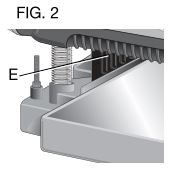
WARNING: Do not remove guards (E, Fig. 2). Serious injury could result.
WARNING: To reduce the risk of serious personal injury, turn tool off and disconnect tool from power source before making any adjustments or removing/installing attachments or accessories. An accidental start-up can cause injury.
TO ATTACH THE DEPTH ADJUSTMENT CRANK HANDLE (FIG. 3)
- Remove the screw located in the crank handle shaft.
- Insert the crank handle (F) over the shaft.
- Secure in place with the screw and T-wrench (G) provided.
DUST EJECTION PORTS
Your planer comes with a dust ejection port. The round port (I) as shown below is for use with a 4″ (100 mm) dust collector hose.
TO SET UP DUST EJECTION
- Select the port (I).
- Depress the lock button (K) on the chip ejection chute (H).
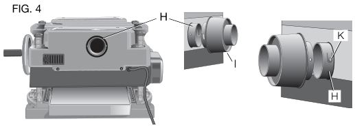
- Slide the notches in the dust port over the pins on the chip ejection chute.
- Rotate the port until the button engages the dust ejection chute and locks in place.
WARNING: Do not operate your planer without the dust ejection port locked into place. Do not insert anything into the dust ejection chute unless the planer is unplugged and you are clearing a clog or obstruction in the unit. Do not get your face or eyes near the dust ejection port when the planer is in operation. Serious injury could result.
WARNING: Chips are ejected at significant velocity. Keep hands and face clear of dust ejection port.
TO REMOVE THE DUST EJECTION PORT
- Use the T-wrench to depress the lock button (K) on the dust chute.
- Twist the port until the pins are disengaged from the notches on the port.
- Pull the dust ejection port off of the dust chute.
OPERATION
WARNING: To reduce the risk of serious personal injury, turn tool off and disconnect tool from power source before making any adjustments or removing/installing attachments or accessories. An accidental start-up can cause injury.
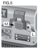
On/Off Switch
To turn the planer on, lift the switch (L) up. The planer locks on automatically. To turn the tool off, press the switch down. A hole (M) is provided under the switch for insertion of a padlock to lock off the planer.
Depth Adjustment
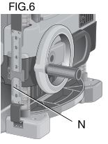
DEPTH ADJUSTMENT SCALE
The depth adjustment scale (N), located on the right front of your planer, indicates the finished thickness of your workpiece. One rotation of the depth adjustment crank is equal to 1/16″ (1.6 mm), half rotation is equal to 1/32″ (0.8 mm), etc.
DEPTH ADJUSTMENT CRANK
Turning the crank clockwise lowers the cutter head. Turning the crank counterclockwise raises the cutter head.
Material Removal Gauge
Your planer is equipped with a material removal gauge (O). It is used to indicate the amount of wood that will be removed in one pass with the carriage set at its current height.
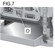
TO USE THE MATERIAL REMOVAL GAUGE
- Slide approximately 3″ (75 mm) of your ma terial under the middle of the carriage.
- Be sure the wood is lying flat against the base of the planer. If the material is inserted at an angle, the reading may be inaccurate.
- Crank the carriage down on the ma terial until the material removal bar engages the wood. You will see the red arrow begin to move up the scale indicating the amount of material to be removed with the carriage at that height.
- Adjust the carriage height until the desired depth of cut appears on the gauge.
- Pull the material out from under the carriage.
- Turn the unit on and feed your material into the cutter head.
NOTE: Do not exceed the recommended depth of cut for various widths of material recommended on the material removal gauge.
WARNING: DO NOT switch the unit on with the material positioned under the carriage. Serious injury could result.
Speed Selection
NOTE: Only switch speeds when the planer is running.
Your planer has the ability to feed material at two different speeds. The two-speed feature (P) was designed to improve efficiency when planing and to provide the best possible surface finish to a variety of materials.
To remove material thickness more quickly, set the unit at speed “2”. This setting delivers 96 cuts per inch to the material.
For finishing, set the unit to speed “1”. Speed “1” is ideal for ensuring the finest finish on the last pass before your final thickness is achieved.
NOTE: When planing particularly hard or figured species of wood, speed “1” is recommended. The slower feed rate will reduce knife wear and tear-out by delivering 179 cuts per inch to the material.
Fan-Assisted Chip Ejection System
Your planer is equipped with a fan-assisted chip ejection system to aid in exhausting chips from the unit. The fan-assisted chip ejection system will work in conjunction with independent dust collection systems.
NOTE: It is not recommended that a shop vac be connected to the DW735. The capacity of most vacs does not support the volume of chips ejected during planing. The vacuum hose may clog stopping the flow of chips.
See the Troubleshooting Guide, for additional information.
Automatic Carriage Lock
There is no manual carriage lock on your planer. A device that automatically minimizes the movement that causes snipe during planing is designed into the four threaded posts.
Turret Stop
Your planer is equipped with a turret stop (Q) for repetitive planing at pre-set depths. Stops are set at 1/8″ (3 mm), 1/4″ (6.5 mm), 1/2″ (12.7 mm), 3/4″ (19 mm), 1″ (25.5 mm), and 1-1/4″ (32 mm).
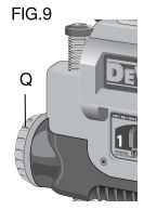
TO SET THE MINIMUM DEPTH TO WHICH THE CARRIAGE CAN TRAVEL WITH THE TURRET STOP
- Be sure the carriage is set above 1-1/4″ (32 mm) before trying to set the turret stop.
- Turn the dial on the front left of the planer until the desired thickness setting aligns with the red indicator, then lower the carriage.
- Plane the workpiece at desired increments until the correct final thickness is achieved.
NOTE: Do not use force to crank the carriage below the level that the turret stop indicates. Permanent damage to the height adjustment system on your planer will result.
PLANING BASICS
Proper Planing Technique
TO PLANE YOUR MATERIAL
- Lower the carriage to the desired height for your first pass.
- Turn the unit on and feed the material into the feed rollers.
- Examine the finished cut and adjust the carriage to the appropriate height for your next pass.
NOTE: Flip the board back and forth between each pass as recommended in Proper Planing Techniques.
See the Troubleshooting Guide, for additional information.
WARNING: DO NOT turn the unit on with the material already inserted under the carriage. Wait until the rollers and cutter head are up to full speed before feeding your material into the machine.
For best results, plane both sides of the workpiece to reach a desired thickness. For example, if you need to remove 1/8″ (3 mm) from your workpiece, remove 1/16″ (1.6 mm) from each side. This not only allows the workpiece to dry with an even moisture content, it also produces finer cuts.
WARNING: Plane only wood that is free from foreign objects, with no loose knots and as few tight knots as possible. Do not plane wood that is severely warped, twisted, knotted or bowed.
WARNING: Do not place your body between the rear of the planer and a stationary object while material is feeding. Serious injury could result.
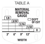
MINIMUM/MAXIMUM WIDTH/HEIGHT/DEPTH
NOTE: Always plane in the direction of the grain. Support the workpiece adequately at all times. Planing material less than 3/4″ (19 mm) wide is not recommended. If you must plane narrow material, group several pieces together and plane them as one wide workpiece whenever possible.
The maximum depth of cut your planer can take in one pass is 1/8″ (3 mm) [on material less than 6″ (152 mm) wide]. Never attempt to modify your planer to take a deeper cut. Follow the recommended depth/width of cut guidelines shown in Table A for best results.
Snipe
Snipe is a depression made when an unsupported end of your material drops toward the floor, causing the opposite end to lift up into the cutter head.
TO AVOID SNIPE
Feed the workpiece into the planer so it is level and remains flat against the base at all times.
Keep the workpiece level throughout planing operation by receiving or “catching” it from the rear of the planer.
If you are planing material that is especially long, the use of additional material support is recommended.
Twisted, Cupped and Bowed Wood
If both sides of your material are very rough or if the material is cupped, bowed or twisted, your planer may not produce the
desired result. Ideally, you should have at least one level face/surface on your material before you plane. Your thickness planer will work best with material that has been run through a jointer to produce one flat surface. If you do not have at least one flat surface or a jointer, see the following recommendations.
TO PLANE TWISTED WOOD (FIG. 11)
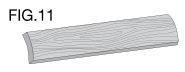
WARNING: Twisted wood may jam your thickness planer. If a jam occurs, turn the power off, disconnect the power supply and raise the carriage to release the material from the cutter head.
If your material is only slightly twisted:
Plane both sides alternating from one to the other until the desired thickness is reached.
TO PLANE CUPPED WOOD (FIG. 12)
To obtain the best possible results with cupped wood:
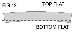
Rip the material down the middle and plane it as two separate pieces. Ripping the material reduces the severity of the cup and allows the machine to deliver better results. Understand that you will have to remove more material on cupped wood to achieve the desired thickness than you would on a normal board.
If ripping the material is not an option:
Plane one side of the material until flat, then plane the opposite side until it is also flat.
NOTE: Do not flip the board back and forth between each pass as recommended by the general planing directions.
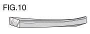
TO PLANE BOWED WOOD (FIG. 13)
The feed rollers and cutter head in your planer will push the bow out of the material as it feeds. However, when the material exits the planer, the pressure of the rollers and cutter head will release allowing the wood to spring back into a bowed formation. To properly remove the bow, use a jointer.

Changing the Planer Knives
WARNING: To reduce the risk of serious personal injury, disconnect the planer from the power source before attempting to change or access the knives. An accidental start-up can cause injury.
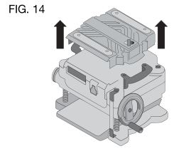
TO CHANGE PLANER KNIVES (FIG. 14–19)
- Use the T-wrench to remove the four screws in the top of the planer.
- Lift the top off (Fig. 14) and place it aside.
- Remove the three wing nuts that seal the dust shroud over the cutter head.
- Rotate the dust shroud up so the round connection that locks onto the fan housing is in the open position (Fig. 15).
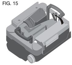
- Push the dust shroud to the left so it disengages from the fan housing.
- Take the dust shroud out of the unit (Fig. 16) and set it aside.
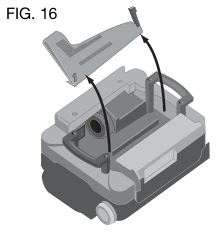
- The cutter head is now exposed.
If the eight screws in the cutter head clamp are not visible, use a piece of scrap wood to carefully rotate the cutter head (Fig. 17) until the screws are accessible and the cutter head lock lever (R) engages. This will prevent further rotation of the cutter head as you change the knives.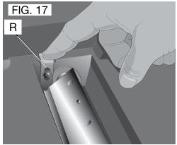 WARNING: Keep your fingers away from the cutter head at all times. Use the tool provided to handle the knives.
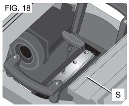
 - Use the T-wrench to remove the eight screws on the knife clamp and set them in the small screws bin (S) on the front panel of the planer (Fig. 18).
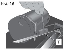
- Use the magnets on the top of the T-wrench to attract the knife clamp and lift it off of the cutter head. One of the knives should now be exposed.
- Use the magnet (T) on the top of the T-wrench (Fig. 19) to attract the knife. Avoid touching it with your fingers.
If only one side of the knife is worn:
- Turn the knife around so that the sharp, unused edge hangs over the end of the cutter head where it will cut the material. Be sure to set the oblong holes in the knife over the pins machined on the cutter head.
- Reset the knife clamp over the knife. Be sure to align the beveled edge on the clamp with the sharp, cutting edge of the knife. If these are not aligned correctly, the clamp will not secure the knife properly.
- Install the screws into the clamp and tighten sufficiently.
To access the other two knives:
- Depress the cutter head lock lever (R) as shown in Figure 17.
- Use the piece of scrap wood to carefully turn the cutter head until it locks into place revealing another knife clamp.
- Follow the same knife change procedure indicated above.
- Repeat the procedure for the last dull knife.
After installing new knives:
- Insert the round end of the dust shroud into the fan housing and rotate it down to lock it into place.
- Place the three wing nuts back into the shroud.
- Screw the top cover of the planer back onto the unit.
NOTE: The planer will not operate if the top cover is not placed correctly.
MAINTENANCE
WARNING: To reduce the risk of serious personal injury, turn tool off and disconnect tool from power source before making any adjustments or removing/installing attachments or accessories. An accidental start-up can cause injury.
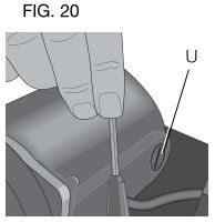
Brush Change (Fig. 20)
Your planer is equipped with brush caps (U) that are external to the motor. If your brushes need to be replaced, begin by acquiring a new set from a DEWALT service center or a dealer authorized to service DEWALT products. Use only identical DEWALT brushes.
TO REPLACE THE BRUSHES ON YOUR PLANER (FIG. 21)
- Use the T-wrench to remove the top cover and brush cover screen on the planer.
- Use a flathead screwdriver to unscrew the brush cap located in the right, rear of the unit (V).
- Do the same for the brush cap located on the side of the motor, inside the planer cover.
- Place the new brushes into the brush holders.
- After installing the brushes, replace the top cover and brush cover screen.
- Before using the planer, run the unit for 10 minutes to seat new brushes.
NOTE: If existing brushes do not need replacing, be sure to maintain the same orientation when you reinstall them.
Calibrating the Depth Adjustment Scale (Fig. 22)
The depth adjustment scale (N) on your planer is set at the factory. However, with extended use, the depth adjustment scale could show an incorrect measurement.
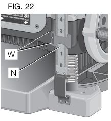
To check the depth adjustment scale, plane a piece of scrap wood, noting the measurement on the depth adjustment scale.
Measure the finished thickness of the workpiece. If the thickness of the workpiece does not match the reading on the depth adjustment scale, loosen the two screws (W) on the red indicator. Adjust the pointer up or down until its reading matches the finished thickness of the workpiece. Securely re-tighten the screws.
Base Maintenance
Keep the table clean and free from oil, grease, and pitch. Treat the table with paste wax to help maintain its smooth finish.
Circuit Breaker Reset Button (Fig. 23)
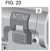
Your planer is equipped with an 18 amp circuit breaker. If your planer becomes overloaded and stops operating, turn off the planer, let the unit sit for 2 minutes and press the reset button (X) before you resume working.
WARNING: To prevent the planer from starting unexpectedly if power is interrupted by a circuit breaker trip, make sure the switch is in the OFF position before restoring power.
NOTE: Circuit breaker overload is often the result of dull knives. Change your knives on a regular basis to avoid tripping your breaker. Check your knives before re-setting the circuit breaker and continuing to plane.
See the Troubleshooting Guide for additional information on circuit breaker trips.
Replacing the Drive Belt
Drive belts are available at extra cost at D E WALT authorized service centers. Replacement of the drive belt should be performed by qualified service personnel.
Chip Ejection Fan (Fig. 24)
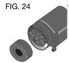
The chip ejection fan on your planer should be cleaned or cleared of debris periodically.
WARNING: Turn off and unplug the planer prior to accessing the chip ejection fan.
TO ACCESS THE FAN
- Remove the top cover of the planer with the T-wrench.
- Remove the dust shroud (Fig. 14–16) and place it aside.
- Remove the screws and clips around the fan housing.
- Remove the fan housing and place it aside as shown. The fan will now be exposed for cleaning.
See the Troubleshooting Guide for additional information.
WARNING: Be sure to properly attach the fan housing and assemble the shroud and top cover correctly before using your planer again.
Accessories
WARNING: Since accessories, other than those offered by DEWALT, have not been tested with this product, use of such accessories with this tool could be hazardous. To reduce the risk of injury, only DEWALT, recommended accessories should be used with this product.
Recommended accessories for use with your tool are available at extra cost from your distributor or local service center.
Four accessories are available for the DW735 Thickness Planer.
- DW7350 Mobile Stand
- DW7351 Folding Tables
- DW7352 13″ (325 mm) Knives
- DW7353 Chip Ejection Accessory
If you need any assistance in locating these accessories, please contact D E WALT Industrial Tool Co., 701 East Joppa Road, Baltimore, MD 21286 or call 1-800-4-D E WALT (1-800-433-9258) or www.dewalt.com
DW7351 Accessory Folding Tables (Fig. 25)
WARNING: For your own safety, read the tool instruction manual before attaching the tables. Failure to heed these warnings may result in personal injury and serious damage to the planer and the accessory. When servicing this tool, use only identical replacement parts. Have damaged cords replaced by an authorized service center.
Your DW7351 folding table box should include
2 folding tables
4 cap screws
4 springs
4 nuts
4 stepped bolts

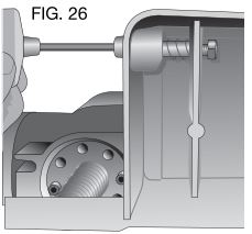
SET-UP AND INSTALLATION OF BASE HARDWARE (FIG. 26–28)
- Place planer on a secure table or workbench. Position planer so the front 3-4″ (75–100 mm) of the base can be accessed from the underside.
- Secure the rear of the planer to the table/bench with nails or screws to prevent it from tilting or falling from the table.
WARNING: The planer could tilt or fall from the table if it is not properly secured opposite the end where the folding table is being installed. Serious injury may result. - Place the spring onto the small end of the stepped bolt.
- Insert the end of the bolt with the spring around it into the larger hole on the side of the base.
- Push the stepped bolt all the way through the hole in the first rib on the underside of the planer. The spring should engage the rib slightly and the threads should show on the right side of the rib.
- On the underside of the planer, use a wrench to hold the nut in place while turning the stepped bolt into it. The T-wrench on your planer can be used to turn the stepped bolt until it is fully secured (Fig. 26).
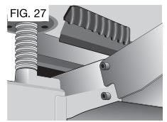
- Install the smaller screw into the lower threaded hole on the side of the base. Use the T-wrench to tighten that fastener securely (Fig. 27).

- Depress the top pin until it is flush with the base and slide the top hole of the table over the pin and release the pin so they lock together (Fig. 27, 28).
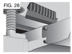
- To attach the table to the rear of the planer, install the bolts and spring following the above procedure.
Your tables should now fold up and down on the top screw and rest on the bottom screw while in position for planing.
NOTE: To transport the planer with the tables, fold them up and carry the unit as recommended by the planer manual.
WARNING: For your own safety, it is recommended that two people carry this machine or serious injury could result.
TO REMOVE THE TABLES
- Depress the spring-loaded bolts on the base and slide each end of the table toward you so they disengage the holes in the tables. You may want to use the T-wrench from your planer to push the bolts flush with the base to easily remove the tables.
- Leave the hardware (stepped bolts and small cap screw) in the base until you need to re-attach the tables.
Repairs
To assure product SAFETY and RELIABILITY, repairs, maintenance and adjustment should be performed by authorized service centers or other qualified service personnel. Always use identical replacement parts.
Register Online
Thank you for your purchase. Register your product now for:
- WARRANTY SERVICE: Registering your product will help you obtain more efficient warranty service in case there is a problem with your product.
- CONFIRMATION OF OWNERSHIP: In case of an insurance loss, such as fire, flood or theft, your registration of ownership will serve as your proof of purchase.
- FOR YOUR SAFETY: Registering your product will allow us to contact you in the unlikely event a safety notification is required under the Federal Consumer Safety Act.
Register online at www.dewalt.com/register.
Three Year Limited Warranty
DEWALT will repair, without charge, any defects due to faulty materials or workmanship for three years from the date of purchase. This warranty does not cover part failure due to normal wear or tool abuse. For further detail of warranty coverage and warranty repair information, visit www.dewalt.com or call 1-800-4-D E WALT (1-800-433-9258). This warranty does not apply to accessories or damage caused where repairs have been made or attempted by others. This warranty gives you specific legal rights and you may have other rights which vary in certain states or provinces.
In addition to the warranty, DEWALT tools are covered by our:
1 YEAR FREE SERVICE
DEWALT will maintain the tool and replace worn parts caused by normal use, for free, any time during the first year after purchase.
90 DAY MONEY BACK GUARANTEE
If you are not completely satisfied with the performance of your DEWALT Power Tool, Laser, or Nailer for any reason, you can return it within 90 days from the date of purchase with a receipt for a full refund – no questions asked.
LATIN AMERICA: This warranty does not apply to products sold in Latin America. For products sold in Latin America, see country specific warranty information contained in the packaging, call the local company or see website for warranty information.
FREE WARNING LABEL REPLACEMENT: If your warning labels become illegible or are missing, call 1-800-4-D E WALT (1-800-433-9258) for a free replacement.
TROUBLESHOOTING GUIDE
IF THE UNIT DOES NOT RUN, CHECK TO SEE:
• if the unit is plugged in.
• if the dust shroud is properly in place.
• if the top cover is properly in place.
• if the circuit breaker needs to be reset.
IF THE MATERIAL DOES NOT FEED PROPERLY, CHECK FOR:
• dull knives.
• excess clogging in the dust shroud.
• excess oil/debris from feed rollers.
• excessively twisted, cupped or bowed material.
• a broken drive belt.
IF CHIPS DO NOT EJECT FROM THE REAR OF THE UNIT, CHECK TO SEE:
• if the dust shroud is properly in place.
• if the dust shroud and fan are clogged or obstructed.
IF THE CIRCUIT BREAKER TRIPS:
• check for dull knives. Dull knives could cause motor overloading.
• reduce depth of cut. An overly aggressive cut could cause motor overloading.
• drop feed rate to 14 ft/min. A reduction in feed rate will reduce the load on the motor and prevent breaker trips.
IF THE BRANCH (HOUSE/SHOP) CIRCUIT BREAKER TRIPS REPEATEDLY:
• unplug or turn off other devices sharing the circuit with the planer OR use the planer on another branch circuit by itself.
• check for dull knives. Dull knives could cause motor overloading.
• reduce depth of cut. An overly aggressive cut could cause motor overloading.
• drop feed rate to 14 ft/min. A reduction in feed rate will reduce the load on the motor and prevent breaker trips.
NOTE: Even under normal loading conditions, other electrical loads on the same branch circuit may cause the circuit breaker to trip.
DOWNLOAD SOURCES
- DEWALT DW735 Portable Thickness Planer Instruction Manual – Download [optimized]
- DEWALT DW735 Portable Thickness Planer Instruction Manual – Download
FAQ’S
How can I tell if my planer is a DW735 or a DW733?
The DW735 has a 3/4″ wide by 2-1/4″ long logo on the front of the planer. The DW733 does not have this logo.
Is the DW735 compatible with the DW733 outfeed table?
No, the DW735 outfeed table is not compatible with the DW733.
What is the maximum depth of cut for this planer?
The maximum depth of cut for this planer is 1/8″.
What is the maximum width of material that can be planed?
The maximum width of material that can be planed with this tool is 13″.
What is the capacity of this thickness planer?
This thickness planer has a capacity of up to 20″ wide by 1-3/8″ thick. It will plane up to a 3/4″ thick board if you use it with an outfeed support stand.
Can I use an outfeed support stand with this tool?
Yes, you can use an outfeed support stand with this tool. However, it will only plane boards up to 3/4″ thick. If you want to plane boards thicker than 3/4″, you will need to purchase an additional infeed and outfeed support stand (DWA1255). These stands are sold separately from the tool and are not included in the box. You can also purchase them from your local hardware store or online retailer. To order these stands, go to www.dewalt.com/planers-jointer-support-stands and enter your zip code into the “Find a Store” field at the bottom right corner of the page. Then click “Find Stores.” If your local hardware store or online retailer does not carry them, they can be ordered directly from us at 1-800-433-9258 (Monday – Friday 8 a.m.-5 p.m., EST). Please have your planer’s model number available when ordering these stands so we can ensure that you receive the correct stands for your tool.
Does the Dewalt DW735 come with blades?
Your DeWALT DW735 comes with them already installed and then when it’s time to replace them… surprise! You have one more use because they’re reversible. But when it’s time to replace them, you can pick up a double pack (6 blades) of the DeWALT 13″ Planer knives for under $80.
Can you run painted wood through a planer?
It is okay to plane most types of painted wood but the blades may dull faster. For safety and environmental reasons, planing painted wood with lead based or cementitious (waterproofing) paint is NOT RECOMMENDED.
Can you sand out planer snipe?
If it’s really small and light, you might get away with a little sanding on the ends, or you can run it through the planer again at a smaller thickness.
Does a planer have to be level?
If the surface isn’t flat you’ll end up getting snipe when your board runs off that bump. The cutter head will be removing material relative to the bed, so any defects in the bed will certainly translate into how the cutter meets the board.
Does a planer make wood smooth?
If neither face is true, a jointer/planer can be used to smooth one face, then the other side can be planed parallel to the first on the thickness planer.) The freestanding planer is a near relation of the jointer/planer. It, too, cuts with a cutter head, but the planer smooths the face of much wider stock.
How do you prevent tears from a planer?
To best prevent this, you need two things. First, use a plane with an adjustable mouth, so you can close it down close to the blade [Photo below] to limit the thickness of the shavings you’ll make. Second, you want a steeper cutting angle of 50–55°.
VIDEO
DEWALT DW735 Portable Thickness Planer
www://dewalt.com/
DEWALT DXMA1902095 Jobsite Pro-X1 Wireless Earbuds with Charging Case

Instruction Manual
WARNING: TO REDUCE THE RISK OF INJURY, USER MUST READ ALL INSTRUCTIONS BEFORE OPERATING THIS PRODUCT
SAVE THESE INSTRUCTIONS
Thank you for purchasing the Jobsite Pro-X1 True Wireless Earbuds with Charging Case and Wall Charger With this wireless headset, you can:
- Enjoy convenient wireless hands free calls
- Control wireless music
- Switch between calls and music
Package Contents
- True Wireless Earbuds – left and right
- Charging case
- Type C charging cable
- 1-Port Wall Charger
- Earbud cushions – 8 sets of cushions
- User manual
COMPONENTS AT A GLANCE
TRUE WIRELESS EARBUDS:
- In Ear Smart Sensor
- LED indicator (earbud)
- Multi-function button(on/off/pause)

CHARGING CASE:
- Battery light indicator
- Factory reset button
- Type C charge port


EARBUD CUSHIONS:
- 8 sets of cushions:

1-PORT WALL CHARGER:
- OUSB

CHARGER CONNECTOR CABLE:
- Type C to USB

DEFINITIONS: SAFETY GUIDELINES
The definitions below describe the level of severity for each signal word. Please read the manual and pay attention to these symbols.
DANGER:
- Indicates an imminently hazardous situation which, if not avoided, will result in death or serious injury.
- Indicates a potentially hazardous situation which, if not avoided, could result in death or serious injury.
- Indicates a potentially hazardous situation which, if not avoided, may result in minor or moderate injury.
- Indicates a practice not related to personal injury which, if not avoided, may result in property damage.
CHARGE THE CASE
Connect the Type C end of the USB cable into the charging case, and USB A end into the included wall charger.
- Charging process is indicated by the white LED light on the front panel.
- When the charging case is fully charged, the white light stays on.
CHARGE EARBUDS
- Place the earbuds in the charging case. The earbuds will start charging.
PAIR THE EARBUDS WITH YOUR BLUETOOTH DEVICE
Take both earbuds from the charging case, the earbuds will power on automatically, entering pairing mode.
- When taking out both earbuds, there will be a voice, “POWER ON -Battery HIGH (or battery medium or battery low}-Pairing” after the voice you will hear two “DOO-DOO”, which means both earbuds are connecting to the Bluetooth device. If unable to connect to previous playing device, it will take 5-10 seconds, the earbuds will flash red and blue. The earbud is now in pairing mode and will voice “PAIRING” from both earbuds.
- Turn on the Bluetooth function of your Bluetooth device and pair the earbuds with your Bluetooth device.
- When successfully connected to a phone or other Bluetooth device, the Blue LED will stay on for 1 second, then voice,”Your device is connected”.
THE FOLLOWING DIRECTIONS SHOW YOU HOW TO PAIR THE EARBUDS WITH YOUR BLUETOOTH DEVICE
Turn on the Bluetooth function of your Bluetooth device, select DEWALT TWS 209A. Enter the earbuds password “0000” if prompted. For those Bluetooth device featuring Bluetooth 3.0 or higher, no need to enter a password.
SINGLE EARBUD PAIRING (MONO MODE}
Take either earbud from the charging case, the earpiece will power on automatically. Search for DEWALT TWS 209A and tap to connect. Once the pairing has succeeded, you will hear a voice “Your device is connected” and the indicator light will be off.
PAIR THE EARBUDS WITH ANOTHER BLUETOOTH DEVICE
If you have another Bluetooth device that you want to pair with the earbuds, make sure the Bluetooth function in any other previously paired or connected devices are turned off. Then follow the steps in “Pair the earbuds” with your Bluetooth device at the first time.
CONNECT THE EARBUDS TO YOUR BLUETOOTH DEVICE
Turn on the Bluetooth function of your Bluetooth device. Take both earbuds from the charging case, the earbuds will power on and reconnect automatically. If no device is connected,the earbuds will automatically turn off after 2 minutes. Both earbuds are now powered on and are paired with each other automatically. The earbuds will search for the previous connected Bluetooth device and reconnect to it automatically. If the last connected one is not available, the earbuds will search and reconnect to the next most recently connected device.
CONTROLS
- To turn earbuds ON: remove from the charging case. Earbuds automatically power on.
- To turn earbuds OFF: place back in charging case and close cover. The first and fourth LED on charging case will stay on for 5 seconds. This indicates the earbuds are off and are charging.
MANAGE YOUR CALLS AND MUSIC:
- To play or pause music:
Press the Multi-Function button once (left or right)
- Multi-Function button
- Forward (next song):Press V+ for 2 seconds Volume increase press V+
- Backward (previous song):Press V- for 2 seconds Volume decrease press V-

CALL CONTROL
USE THE MULTI-FUNCTION BUTTON
- Answer/Hang up:
Press the multi-function button once (left or right) - Reject incoming call:
Press the multi-function button (left or right) and hold for 2 seconds - Switch caller during call:
Press the multi-function button (left or right) twice - Voice Control – Siri/Google:
Press the multi-function button twice (left or right) - Low battery level:
The Red LED will flash 3 times every 2 seconds and will voice,”Battery Low”, every 100 seconds - Battery is fully charged:
The LED is off
Earbuds feature an IPX6 rating for protection against sweat and water.
LED INDICATOR – CHARGING CASE
Close the charging case cover for earbuds to charge. The firstand fourth LED will stay on for 5 seconds.
- 4 White LED lights= 75-100% power
- 3 White LED lights= 50-75% power
- 2 White LED lights = 25-50% power
- 1 White LED lights = 0-25% power
- LED Indicator lights:

LED INDICATOR – CHARGE CASE WITH EARBUDS INSIDE
While charging the case, White LED status:
- 3 White LED lights stay on and the 4th LED flashes everysecond for 75-100% power
- 2 White LED lights stay on and the 3rd LED flashes everysecond for 50-75% power
- 1 White LED lights stay on and the 2nd LED flashes every second for 25-50% power
- 1 White LED light flashes every second for 0-25% power
FACTORY RESET
- Place earbuds into the charging case and keep case open.
- Press the factory reset button twice and it will be disconnected from paired mobile devices and reset to factory setting.
TECHNICAL DATA – EARBUDS
- Music time: Up to 7.5 hours per charge (total up to 30 hours with charging case)
- Talk time: Up to 6 hours per charge (total up to 24 hours with charging case)
- Standby time:220 hours
- Charging time: 1.5 hours
- Rechargeable Li-ion battery: 55mAh on each earpiece Bluetooth version: 5.0
- Compatible Bluetooth profiles:
- HFP
- A2DP
- HSP
- AVRCP
- Supported audio codec: SBC
- Frequency band: 2.4 GHz ISM Band
- Transmitter power: :,; 4 dBm
- Operating range: 10 meters (33 feet)
- Charging time: 2 hours
- Rechargeable Li-ion battery: 500mAh
- Input: 100-240V AC, 50-60Hz, 0.35A
- Output: 5V= 1A
IMPORTANT SAFETY INSTRUCTIONS FOR ALL
RECHARGEABLE BATTERY PACKAGING
The battery is not fully charged out of the carton. Before using the earbuds, read the safety instructions below and then follow the charging procedures outlined. Do not incinerate the battery module even if it is severely damaged or is completely worn out. The battery can explode in a fire. Toxic fumes and materials are created when lithium batteries are burned. If battery contents come into contact with the skin, immediately wash area with mild soap and water. If battery liquid gets into the eye, rinse water over the open eye for 15 minutes or until irritation ceases. If medical attention is needed, the battery electrolyte is composed of a mixture of liquid organic carbonates and lithium salts.
Contents of opened battery cells may cause respiratory irritation. Provide fresh air. If symptoms persist, seek medical attention.These earbuds are splash and water resistant and was tested under controlled laboratory conditions with a rating of IPX6 under IEC standard 60529. Splash and water resistance are not permanent conditions and resistance might decrease as a result of normal wear. Do not attempt to charge wet earbuds; To dry your earbuds, tap it gently against your hand with the port cover open to remove excess liquid. Leave your powerbank in a dry area with some airflow. Placing your earbuds in front of a fan blowing cool air directly onto the earbuds might help the drying process. The charge case does not have an IP rating. Liquid damage is not covered under warranty.
STORAGE RECOMMENDATIONS
- The best storage place is one that is cool and dry, away from direct sunlight and excess heat or cold.
- For long storage, it is recommended to store the earphones in a cool dry place for optimal results.
WARNING:
- DO NOT leave earbuds or charge case in any location with excessive heat.
- DO NOT charge or use the battery in explosive atmospheres, such as in the presence of flammable liquids, gases or dust.
- DO NOT modify the battery in any way to fit a non-compatible charger as the battery may rupture causing serious personal injury.
- DO NOT splash or immerse in water or other liquids. A WARNING: DO NOT store or use the earbuds in locations where the temperature may reach or exceed 105° F (40° C) (such as outside sheds or metal buildings in summer). For best life, store earphones in a cool, dry location. The True Wireless Earbuds should not be disposed of as municipal solid waste. To recycle it, contact your local hazardous waste processor or contact Call 2 Recycle® on their website, call2recycle.org, or by phone at 877-273-2925 to find the nearest drop-off location for lithium-polymer batteries.
- Burn hazard. Battery liquid may be flammable if exposed to spark or flame.
- Fire hazard. Never attempt to open the battery pack for any reason. If the battery pack is cracked or damaged, do not insert the charging cable. Do not crush, drop or damage the battery. Do not use the earphones if they have received a sharp blow, been dropped, run over or damaged in any way (e.g. pierced with a nail, hit with a hammer, stepped on).
Damaged batteries should be returned to a service center for recycling.
LIMITED LIFETIME WARRANTY
We’re here to help. If you are not satisfied with this product or We’re here to help. If you are not satisfied with this product or
NOT NEED TO CONTACT THE RETAILER.
Please contact one of our service representatives, using the contact info listed below. Please provide the product number when contacting us.
PLEASE CALL CUSTOMER SERVICE: 888-480-9885,
8:00 a.m.-5:00 p.m. PT, Monday – Friday,
or e-mail us using: [email protected]
E-filliate Inc.11321 White Rock Road
Rancho Cordova, CA 957 42 USA
DEWALT Two-Way Radio

Before operating the radio, please read all safety and operating instructions. Save all instructions in a safe place for future reference.
Important Safety Instructions
- Only accessories included in this package or specified by the manufacturer should be used with the radio. The 5V micro-USB charging input is compatible with most high quality micro-USB chargers that fully conform to the USB standards.
- Do not use cleaners or solvents to clean the exterior of the radio. Use only a damp or dry cloth.
- Do not attempt to service the radio yourself. Removing the cover will void the warranty. Changes or modifications not expressly approved by DEWALT may void the user’s authority granted by the FCC to operate this device and should not be made.
- Do not plug the wall adaptor into the power outlet if the outlet is wet.
I
- Do not incinerate the battery even if it is severely damaged or is completely worn out.
- Do not discard battery in a fire. The battery pack can explode in a fire.
- Do not replace battery in any area labeled “Hazardous Atmosphere”. Any sparks created in a potentially explosive atmosphere can cause an explosion or fire.
- Do not disassemble, crush, puncture, shred, or otherwise attempt to change the form of your battery.
- Do not dry a wet or damp battery with an appliance or heat source, such as a hair dryer or microwave oven.
- A small leakage of liquid from the battery cells may occur under extreme usage or temperature conditions. This does not indicate a failure. Do not open, deform or mutilate the battery as there may be corrosive materials which can cause damage to eyes or skin and may be toxic if swallowed.
However, if the outer seal is broken and this leakage gets on your skin:
-
- Wash quickly with soap and water.
- Neutralize with a mild acid such as lemon juice or vinegar.
- If battery liquid gets into your eyes, flush them with clean water for a minimum of 10 minutes and seek immediate medical attention.
This product uses Lithium Polymer Battery. Do not transport package if damaged, a fire hazard could exist.
For more information, please call our customer support line at (866) 208-1654.
Recycle Battery
Local, state or federal laws may prohibit disposal of batteries in ordinary trash. Consult your local waste authority for information regarding available recycling and/or disposal options.
Introduction
Making Life Easier and Safer
Staying in touch is convenient and easy when using your radio. Some of the many uses you will discover include:
Communicating with others while hiking, biking, and working; keeping track of family and friends at a crowded public event; checking with travel companions; connecting with neighbors; arranging meeting spots with others while shopping at the mall, talking with your colleagues in warehouse or jobsite.
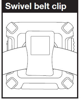
Secure your radio while on the go:
Carrying your radio with you is easy when using the swivel belt clip. The swivel belt clip easily attaches to your belt, purse, or backpack.
Product Service & Support
For any questions about operating this new DEWALT branded product, PLEASE CONTACT US FIRST… do not return this product to the retail store. The contact information for support will vary depending on the country in which you purchased and utilize the product.
To obtain warranty service or other information for products purchased from Altis itself or through its authorized reseller or agent and utilized in the U.S.A., please call our consumer support line at (866) 208-1654. You will receive instructions on how to ship the products at your expense to an our Authorized Service Center. To obtain service, you must include: (a) a copy of your receipt, bill of sale or other comparable proof of purchase; (b) a written description of the problem; and, most importantly; (c) your address and telephone number.
For further information needed on its features, please visit DEWALT.COM for frequently asked questions and the electronic manual.
©2019 Altis Global Limited, Atlanta, GA USA.
Operational Cautions
Exposure to high volume sound levels may cause temporary or permanent damage to your hearing. Although there is no single volume setting that is appropriate for everyone, you should always use your radio with the volume set at low level and avoid prolonged exposure to high volume sound levels.
- Set the volume control in a low position and use as low a volume as possible.
- Avoid turning up the volume to block out noisy surroundings. Whenever possible, use your radio in a quiet environment with low background noise.
- Limit the amount of time you use headsets or earpiece at high volume levels.
- When using the radio without a headset or earpiece, do not place the radio’s speaker directly against your ear.
- Observe all signs and instructions that require an electrical device or RF radio product to be switched off in designated areas, such as gas/refueling stations, hospitals, blasting areas, potentially explosive atmospheres, or aircraft.
- If you experience a skin irritation after using this product, discontinue use and seek medical attention.
- If the product or charger: overheats; has a damaged cord or plug; has been dropped or damaged; has been dropped into water, disconnect any charger from its power supply, discontinue use of the product.
Electromagnetic Interference
Nearly every electronic device is susceptible to electromagnetic interference (EMI) if inadequately shielded, designed, or otherwise configured for electromagnetic compatibility. Turn off your radio in any facility where posted notices instruct you to do so. These facilities may include hospitals or health care facilities that may be using equipment that is sensitive to external RF energy.
- When instructed to do so, turn off your radios when on board an aircraft. Any use of a RF device must be in accordance with applicable laws, regulations and airline crew instructions.
- Some radios may interfere with some hearing aids. In the event of such interference, you may want to consult your hearing aid manufacturer or physician to discuss alternatives.
- If you use any other personal medical device, consult the manufacturer of your device to determine if it is adequately shielded from RF energy. Your doctor or physician may be able to assist you in obtaining this information.
Product Features
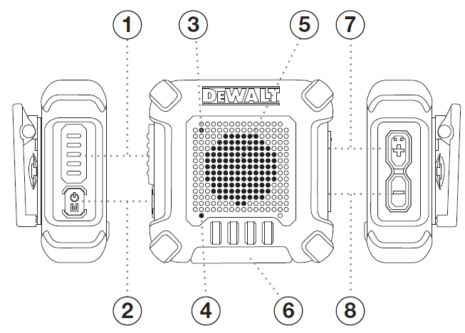
- Talk Button
- Power / Menu Button
- LED Indicator
- Built-In Microphone
- Built-In Speaker
- Micro USB Charge / Audio Jack
- Volume / Channel (+) Button
- Volume / Channel (-) Button
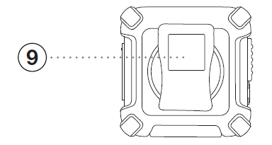
- Swivel Belt Clip
Caring for Your Radio: Your radio will give you years of trouble-free service if cared for properly. Handle the radio gently. Keep the radio away from dust. Never put the radio in water or in a damp place. Avoid exposure to extreme temperatures.
Battery Information: The battery is not charged before delivery, so please charge the battery for your first use. If the battery is not used for a long time or the battery is used up, please charge it before use. Charge / discharge for twice or three times alternately to achieve its optimal performance.
Note:
- Do not cause any short circuit on the battery or throw the battery into fire.
- When charging, please make sure the radio is powered off to guarantee it can be fully charged.
- Unplug the charging cable after it is fully charged. Unnecessary constant charging will shorten the battery life.
- Do not put the fully-charged battery to re-charge, or it may shorten the battery life.
- Please try to keep the battery in an indoor environment at around 25°C. The battery may get easily spoiled after being kept in the environment below – 10°C for a long time.
- In temperatures higher than 35°C or below -10°C, the dischargeable power of the battery may decrease due to the physical property of lithium battery.
Operation
Using Your Radio
For charging radio(s):
- Insert the micro-USB cable into jack located at the bottom of radios.
- Plug the cable into USB compatible power port.
- It will take around 5 hours for a full charge.
- LED indicator
| Power Off the Device during charging | |
| Battery Charging | Solid Red (No flash) |
| Battery Charged | Solid Green (No flash) |
DEWALT recommends your radio be turned off while being charged.
Turning on Your Radio
Press and hold Power/Menu button for 4 seconds to turn the radio on or off. When green LED flashes every 5 seconds, your radio is now in Standby mode, ready to receive transmissions.
The radio is always in Standby mode except when the Talk or Power/ Menu buttons are pressed.
Battery Low
Red LED flashes every 5 seconds. Voice prompt “Please charge” will be heard approximately 30 minutes before device automatically powers off.
Auto Battery Save
If there are no transmissions within 10 seconds, the radio will automatically switch to Battery Save mode. This will not affect the radio’s ability to receive incoming transmissions.
Communicating with Another Person
- Press and hold the Talk button.
- Position the microphone about 6 inches from your mouth, speak in a normal voice.
- Release the Talk button when you are finished talking and listen for a response.
- You cannot receive incoming calls while pressing the Talk button.
You cannot receive incoming calls while pressing the Talk button.
To Select a Channel
To change the channel, press Power / Menu button once, the current channel number prompted. Then, press the + or – buttons to select your channel, and you can: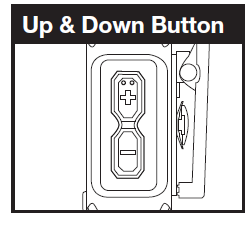
- Fast press to skip voice prompting of every channel number
- Press and hold for fast skipping
It will exit the channel selection mode if there is no + or – button pressing for 5 sec. Or simply press Power / Menu button or Talk button once to return to standby mode immediately.
Listening for a Response
Release the Talk button to receive incoming transmissions. Your radio is always in Standby mode while the Talk button is not pressed.
To Adjust Volume
Press the + or – button to increase or decrease the volume. There are 12 different volume levels.
Do not hold the radio close to your ear. If the volume is set to an uncomfortable level, it could hurt your ear.
Range
- Your range will vary depending on terrain and conditions.
- In flat, open country your radio will operate at maximum range.
- Buildings and foliage in the path of the signal can reduce the range of the radio.
- Dense foliage and hilly terrain will further reduce the range of the radio.
- On Channels 8 through 14, your radio automatically switches to low power, which will limit the range the radio can communicate.
Auto Squelch
Your radio will automatically shut off weak transmissions and unwanted noise due to terrain, conditions limit.
Call Alert
Your radio can alert you to incoming signals by sounding an audible call tone.
Roger Beep Confirmation Tone
Your listener will hear an audible tone when you release the Talk button. This alerts the other party that you have finished talking and it is OK for them to speak.
Key Tone
Key Tone is an audible tone which will sound each time a button is pressed.
LED indicator
| When you press and hold Talk button | Green LED on |
| Standby Mode | Green LED flashes every 5 seconds |
| Battery Low | Red LED flashes every 5 seconds |
| Power Off the Device during charging | |
| Battery Charging | Solid Red (No flash) |
| Battery Charged | Solid Green (No flash) |
IMPORTANT NOTICE:
- WARNING: Changes or modifications to this unit not expressly approved by the party responsible for compliance could void the user’s authority to operate the equipment.
This device complies with Part 15 of the FCC Rules. Operation is subject to the following two conditions: 1) This device may not cause harmful interference, and 2) this device must accept any interference received,including interference that may cause undesired operation.
NOTE: This equipment has been tested and found to comply with the limits for a Class B digital device, pursuant to Part 15 of the FCC Rules. These limits are designed to provide reasonable protection against harmful interference in a residential installation. This equipment generates, uses and can radiate radio frequency energy and, if not installed and used in accordance with the instructions, may cause harmful interference to radio communications.
However, there is no guarantee that interference will not occur in a particular installation. If this equipment does cause harmful interference to radio or television reception, which can be determined by turning the equipment off and on, the user is encouraged to try to correct the interference by one or more of the following measures:
- Reorient or relocate the receiving antenna.
- Increase the separation between the equipment and receiver.
- Connect the equipment into an outlet on a circuit different from that to which the receiver is connected.
- Consult the dealer or an experienced radio/TV technician for help.
Safety Information for Radios
Your wireless handheld portable transceiver contains a low power transmitter. When the talk button is pushed, it sends out radio frequency (RF) signals. The device is authorized to operate at a duty factor not to exceed 50%. In August 1996, the Federal Communications Commissions (FCC) adopted RF exposure guidelines with safety levels for handheld wireless devices
Important
FCC RF Exposure Requirements: For body-worn operation, this radio has been tested and meets the FCC RF exposure guidelines when used with DEWALT accessories supplied or designated for this product. Use of other accessories may not ensure compliance with FCC RF exposure guidelines. Use only the supplied antenna. Unauthorized antennas, modifications or attachments could damage the transmitter and may violate FCC regulations.
Normal Position
Hold the transmitter approximately 2 inches from your face and speak in a normal voice, with the antenna pointed up and away.
FCC Part 15.21 Warning Statement-
NOTE: THE GRANTEE IS NOT RESPONSIBLE FOR ANY CHANGES OR MODIFICATIONS NOT EXPRESSLY APPROVED BY THE PARTY RESPONSIBLE FOR COMPLIANCE. SUCH MODIFICATIONS COULD VOID THE USER’S AUTHORITY TO OPERATE THE EQUIPMENT.
IC RSS-GEN
This device complies with ISED license-exempt RSS standard(s). Operation is subject to the following two conditions: (1) this device may not cause interference, and (2) this device must accept any interference, including interference that may cause undesired operation of the device.
Under ISED regulations, this radio transmitter may only operate using an antenna of a type and maximum (or lesser) gain approved for the transmitter by ISED. To reduce potential radio interference to other users, the antenna type and its gain should be so chosen that the equivalent isotropically radiated power (e.i.r.p.) is not more than that necessary for successful communication. The applicant is responsible for providing proper instructions to the user of the radio device, and any usage restrictions, including limits of exposure durations. The user manual shall provide installation and operation instructions, as well as any special usage conditions, to ensure compliance with SAR and/or RF field strength limits. For instance, compliance distance shall be clearly stated in the user manual.
Radiation Exposure Statement:
Any Changes or modifications not expressly approved by the party responsible for compliance could void the user’s authority to operate the equipment.
For Remote controller, SAR tests are conducted using standard operating positions accepted by the FCC/ISED with the device transmitting at its highest certified power level in all tested frequency bands, although the SAR is determined at the highest certified power level, the actual SAR level of the device while operating can be well below the maximum value.
Before a new model device is available for sale to the public, it must be tested and certified to the FCC that it does not exceed the exposure limit established by the FCC/ISED, Tests for each device are performed in positions and locations (e.g. at the ear and worn on the body) as required by the FCC/ISED.
For body worn operation, this model device has been tested and meets the FCC/ISED RF exposure guidelines when used with an accessory designated for this product or when used with an accessory that Contains no metal and that positions the handset a minimum of 10 mm from the body.
Non-compliance with the above restrictions may result in violation of RF exposure guidelines.
MODEL DXFRS220:
This device complies with part 15 of the FCC Rules. Operation is subject to the following two conditions: 1) This device may not cause harmful interference, and 2) this device must accept any interference received,including interference that may cause undesired operation.
FCC Warnings: Replacement or substitution of transistors, regular diodes or other parts of a unique nature, with parts other than those recommended by DEWALT may cause a violation of the technical regulations of part 95 of the FCC rules, or violation of type acceptance requirements of part 2 of the rules.
Warranty & Trademark Acknowledgment
Limited Lifetime Warranty on Radio
Altis Global Limited warrants to the original consumer purchaser only that this product and the component parts thereof, will be free from defects in workmanship and materials. Altis will, repair or replace, at its sole option and discretion, this product or any defective parts. Altis’ liability hereunder shall be limited to repair or replacement of the defective part or parts, and such correction shall constitute a fulfillment of all of Altis’ warranties hereunder.
This limited lifetime warranty is only valid for the original consumer purchaser in limited jurisdictions and is not transferrable. This limited lifetime warranty will automatically terminate if this product is sold or otherwise transferred to another party. The product must be purchased from Altis or an authorized dealer or the warranty is void. This limited lifetime warranty is valid only for products purchased and utilized in specific jurisdictions. Please visit our website at DEWALT.COM for a list of jurisdictions wherein this lifetime limited warranty is valid.
This limited lifetime warranty does not apply to accessories and consumables and does not cover damage due to misuse, abuse, negligence, acts of God, accident, commercial use or modification of, or to any part of this product. The limited lifetime warranty does not include battery, battery warranty is 180 days from original purchase date; after initial 180 days, owner can return the Radio (at owner’s expense) to Altis for review and can purchase a new battery if necessary. This warranty does not cover damage due to improper operation, maintenance or installation; ordinary wear and tear; or attempted alterations or repairs by anyone other than Altis or someone authorized by Altis to do warranty work. Any unauthorized alterations or repairs will void this warranty. This limited lifetime warranty does not cover product sold AS IS or WITH ALL FAULTS. This limited lifetime warranty is invalid if the factory applied serial number or date stamp has been altered, defaced or removed from this product. This limited lifetime warranty does not cover product purchased or utilized in a jurisdiction not covered.
The procedure for obtaining service and support, and the applicability of this warranty, will vary depending on the country or jurisdiction in which you purchase and utilize the product. For details on obtaining product service, support and other warranty information please visit DEWALT.COM.
This warranty gives you specific legal rights, and you may also have other rights which vary from state to state and country to country.
EXCEPT AS EXPRESSLY SET FORTH IN THIS WARRANTY, ALTIS MAKES NO OTHER WARRANTIES, EXPRESSED OR IMPLIED, INCLUDING ANY IMPLIED WARRANTIES OF MERCHANTABILITY AND FITNESS FOR A PARTICULAR PURPOSE. ALTIS EXPRESSLY DISCLAIMS ALL WARRANTIES NOT STATED IN THIS LIMITED WARRANTY. ANY IMPLIED WARRANTIES THAT MAY BE IMPOSED BY LAW ARE LIMITED TO THE TERMS OF THIS EXPRESSED WARRANTY.
LIMITATION OF REMEDIES AND DAMAGES. REPAIR OR REPLACEMENT AS PROVIDED UNDER THIS WARRANTY IS THE EXCLUSIVE REMEDY OF THE CONSUMER. ALTIS SHALL NOT BE LIABLE FOR ANY INCIDENTAL OR CONSEQUENTIAL DAMAGES, INCLUDING BUT NOT LIMITED TO ATTORNEYS’ FEES AND/OR COSTS OF LITIGATION, FOR BREACH OF ANY EXPRESS OR IMPLIED WARRANTY ON THIS PRODUCT. ALTIS IS NOT LIABLE FOR ANY DAMAGES CAUSED BY THE PRODUCT OR BY THE PRODUCT TO PERFORM, INCLUDING ANY LOST PROFITS, LOST SAVINGS, INCIDENTAL DAMAGES, OR CONSEQUENTIAL DAMAGES. ALTIS IS NOT LIABLE FOR ANY CLAIM MADE BY A THIRD PARTY OR MADE BY YOU FOR A THIRD PARTY. THIS LIMITATION APPLIES WHETHER DAMAGES ARE SOUGHT, OR A CLAIM MADE, UNDER THIS WARRANTY OR AS A TORT CLAIM (INCLUDING NEGLIGENCE OR STRICT PRODUCT LIABILITY), A CONTRACT CLAIM, OR ANY OTHER CLAIM. THIS LIMITATION CANNOT BE WAIVED OR AMENDED BY ANY PERSON. THIS LIMITATION OF LIABILITY WILL BE EFFECTIVE EVEN IF ALTIS OR AN AUTHORIZED REPRESENTATIVE OF ALTIS HAS BEEN ADVISED BY YOU OF THE POSSIBILITY OF ANY SUCH DAMAGES.
Some states and countries do not allow limitations on how long an implied warranty lasts and do not allow the exclusion or limitation of incidental or consequential damages, so the above limitations may not apply to you. This warranty gives you specific legal rights, and you may also have other rights which vary from state to state and country to country.
Provided that the product was purchased from Altis itself or through its authorized reseller or agent and utilized in the U.S.A., Altis will, without charge, repair or replace, at its option, defective products, products or component parts upon delivery to the authorized Altis Global Limited Authorized Service Center, accompanied by proof of the date of first customer purchase, such as a duplicated copy of a sales receipt.
You must pay any initial shipping charges required to ship the product for warranty service, but the return charges, to an address in the U.S.A, will be at Altis’ expense, if the product is under warranty.
For Products Purchased Outside the U.S.A.
Please contact your authorized local reseller or agent for warranty information.
Trademark Acknowledgment
DEWALT® and the DEWALT Logo are trademarks of the DEWALT Industrial Tool Co., or an affiliate thereof and are used under license.
The yellow/black color scheme is a trademark for DEWALT power tools & accessories.
© 2019 DEWALT
U.S. & Canada Only
Made in CHINA
Product Manufactured by: Altis Global Limited, Atlanta, GA USA.
For product, service or warranty information contact us at: DEWALT.COM (866)208-1654![]()

DEWALT DXMA190291 Bluetooth Neckband Earphones

Definitions: Safety Guidelines
The definitions below describe the level of severity for each signal word. Please read the manual and pay attention to these symbols.
- DANGER: Indicates an imminently hazardous situation which, if not avoided, will result in death or serious injury
- WARNING: Indicates a potentially hazardous situation that, if not avoided, could result in death or serious injury.
- CAUTION: Indicates a potentially hazardous situation that, if not avoided, may result in minor or moderate injury.
- NOTICE: Indicates a practice not related to personal injury which, if not avoided, may result in property damage.
IF YOU HAVE ANY QUESTIONS OR COMMENTS ABOUT THIS PRODUCT, CALL US TOLL-FREE AT 888-480-9885.
WARNING! Read and understand all instructions. Failure to follow all instructions listed below may result in electric shock, fire, and/or serious personal injury.
SAVE THESE INSTRUCTIONS
Thank you for purchasing the Jobsite Pro Wireless Earphones. These earphones allow the user to listen to audio wirelessly from up to 33 feet from a paired phone or tablet. Make sure the earphones are fully charged before using them for the first time. See “Charging Procedure” for instructions.
Jobsite Pro Wireless Earphones Safety Warnings
- WARNING: This manual contains important safety and operating instructions for this Jobsite Pro Wireless Earphones. Before using the Jobsite Pro Wireless Earphones, read this manual and all labels on the Jobsite Pro Wireless Earphones.
- Before using the Jobsite Pro Wireless Earphones, read all instructions and cautionary markings on the Jobsite Pro Wireless Earphones.
- Shock hazard. Do not allow any liquid to get inside the Jobsite Pro Wireless Earphones. Electric shock may result
- The Jobsite Pro Wireless Earphones are rated IPX6 and have been tested to withstand powerful water jets for up to 1 minute. They are not designed to be submerged underwater.
- When operating the Jobsite Pro Wireless Earphones outdoors, always provide a dry location.
- Do not operate the Jobsite Pro Wireless Earphones if it has received a sharp blow, been dropped, or otherwise damaged in any way.
- Do not disassemble the Jobsite Pro Wireless Earphones, there are no user-serviceable parts.
Important Safety Instructions for All Rechargeable Batteries
The battery is not fully charged out of the carton. Before using the earphones, read the safety instructions below and then follow the charging procedures outlined.
READ ALL INSTRUCTIONS
- Do not incinerate the battery module even if it is severely damaged or is completely worn out. The battery can explode in a fire. Toxic fumes and materials are created when lithium batteries are burned.
- If battery contents come into contact with the skin, immediately wash area with mild soap and water. If battery liquid gets into the eye, rinse water over the open eye for 15 minutes or until irritate ceases. If medical attention is needed, the battery electrolyte is composed of a mixture of liquid organic carbonates and lithium salts.
- Contents of opened battery cells may cause respiratory irritation. Provide fresh air. If symptoms persist, seek medical attention.
- Do not charge or use the battery in explosive atmospheres, such as in the presence of flammable liquids, gases or dust.
- DO NOT modify the battery in any way to fit a non-compatible charger as the battery may rupture causing serious personal injury.
- DO NOT splash or immerse in water or other liquids
- Do not store or use the earphones in locations where the temperature may reach or exceed 105° F (40° CJ (such as outside sheds or metal buildings in summer}. For the best life, store earphones in a cool, dry location.
- The Jobsite Pro Wireless Earphones should not be disposed of as municipal solid waste. To recycle it, contact your local hazardous waste processor or contact Call 2 Recycle® on their website, cal/2recycle.org, or by phone at 877273- 2925 to find the nearest drop-off location for lithium-polymer batteries.
A WARNING: Burn hazard. Battery liquid may be flammable if exposed to spark or flame.
A WARNING: Fire hazard. Never attempt to open the battery pack for any reason. If the battery pack is cracked or damaged, do not insert the charging cable. Do not crush, drop or damage the battery. Do not use the earphones if they have received a sharp blow, been dropped, run over or damaged in any way (e.g. pierced with a nail, hit with a hammer, stepped on). Damaged batteries should be returned to a service center for recycling.
Charging Procedure:
- Charge the wireless earphones by connecting a TYPE C power-in cable to the earphones’ charging port.
- Plug the USB connector into a USB port on any computer or USB power adapter.
- When charging, a red light on the controller will illuminate. Once the light turns blue, the earphones are fully charged.
- When the battery is empty, it will take up to two hours to fully charge them.
Important Charging Notes:
- Longest life and best performance can beobtained if a device is charged when the air temperature is between 65 °F and 75° (18° – 24 °C). DO NOT charge a device in an air temperature below +40°F (+4.5°C), or above + 105°F (+40.5 °C). This is important and will prevent serious damage to the device.
- The earphones may become warm to the touch while charging. This is a normal condition, and does not indicate a problem. To facil itate the cooling of the earphones after use, avoid placing the earphones in a warm environment such as in a metal shed or an uninsulated trailer
- If the earphones do not charge properly:
- Check operation of the receptacle by plugging in a lamp or other appliance.
- Check to see if the receptacle is connected to a light switch which turns the power off when you turn out the lights.
- Move the earphones to a location where the surrounding air temperature is
approximately 65° F – 75° F (18° – 24 ° C}.
Do not freeze or immerse the earphones in:
water or any other liquid.
A WARNING: Shock hazard. Don’t allow any liquid to get inside the earphones. Electric shock may result.
A WARNING: Burn hazard. Do not submerge the earphones in any liquid or allow any liquid to enter the earphones. Never attempt to open the earphones for any reason. If the plastic housing of the earphones breaks or cracks, return it to a service center for recycling.
Pairing Procedure:
- Place the earphones within one meter of your phone or tablet during pairing
- Power-on the earphones by pressing and holding the key on the earphone controller until you see the indicator light alternately flash blue and red. Voice prompts will indicate pairing mode is enabled.
- Enable the Bluetooth function of your phone or tablet, search the Bluetooth devices and select “DEWALT 2091” for pairing and connection
- After the earphones are successfully paired to your phone or tablet, the blue light on the earphones will blink slowly. Voice prompts will confirm pairing is successful. The pairing mode will be maintained for three minutes. If pairing and connection are unsuccessful beyond two minutes, the headset will automatically switch to stand-by mode.
- After pairing is completed, the earphones and your phone or tablet will recognize each other without pairing again
- To remove the pairing connection, enter the Bluetooth settings of your phone or tablet. Select “DEWALT 2091″ and select the”Forget” option.
Note: that the Jobsite Pro Wireless Ear phone can pair to a max. of 2 devices. If you experience difficulty pairing a new device, remove a pairing connection from an existing device.
Controller Functions:
- On/Off: Press and hold the key to turn on/off.
- Pause: Press the key to pause playback, and press the key again to resume playback.
- Volume increase: Tap the + key; volume reduction: Tap the – key.
Note : that pressing and holding down the -key instead of tapping it will result in starting the current song or audio file from the beginning. Pressing and holding down the + key will result in advancing from one song or audio file to the next. - Advance: press and hold the + key to move forward to the next track
- Return: press and hold the – key for go back to the previous track
- Answer/hangup: press the key for twoseconds and then release it.
Storage Recommendations:
- The best storage place is one that is cool and dry, away from direct sunlight and excess heat or cold.
- For long storage, it is recommended to store the earphones in a cool dry place for optimal results.
Lifetime Limited Warranty:
In case of product failure, E-filliate Inc. will issue a replacement. DO NOT RETURN THE PRODUCT TO STORE. Instead, please call 888-480-9885, 8:00 a.m.-5:00 p.m PT, Monday – Friday, or e-mail us using [email protected].
Products improperly used, abused or altered are not covered under policy.
Customer Service:
We’re here to help. If you have a problem with this product or have questions on how to use it, please contact us. You do not need to contact the retailer you purchased this product from. Please contact one of our service representatives, using the contact info listed above, before shipping merchandise to us. Please provide the product number, DXMA 1902091, when contacting us.
11321 White Rock Road
Rancho Cordova, CA 957 42 USA
DEWALT 20V Max* String Trimmer DCST922
DEWALT 20V Max* String Trimmer DCST922
Instruction Manual
model no: DCST922
20V Max* String Trimmer
www.DEWALT.com
If you have questions or comments, contact us.
1-800-4-DEWALT
Definitions: Safety Alert Symbols and Words
This instruction manual uses the following safety alert symbols and words to alert you to hazardous situations and your risk of personal injury or property damage.
![]() DANGER: Indicates an imminently hazardous situation which, if not avoided, will result in death or serious injury.
DANGER: Indicates an imminently hazardous situation which, if not avoided, will result in death or serious injury.
![]() WARNING: Indicates a potentially hazardous situation which, if not avoided, could result in death or serious injury.
WARNING: Indicates a potentially hazardous situation which, if not avoided, could result in death or serious injury.
![]() CAUTION: Indicates a potentially hazardous situation which, if not avoided, may result in minor or moderate injury.
CAUTION: Indicates a potentially hazardous situation which, if not avoided, may result in minor or moderate injury.
(Used without word) Indicates a safety related message.
![]() NOTICE: Indicates a practice not related to personal injury which, if not avoided, may result in property damage.
NOTICE: Indicates a practice not related to personal injury which, if not avoided, may result in property damage.
Fig. A

- Variable speed trigger
- Lock-off button
- Speed control switch
- Auxiliary handle
- Motor housing
- Locking lever
- Pole latch
- Pole clasp
- Guard
- Spool housing
- Battery housing
- Battery pack
- Battery release button
- Handle
- Upper pole
- Lower pole
![]() WARNING: Read all safety warnings and all instructions. Failure to follow the warnings and instructions may result in electric shock, fire and/or serious injury.
WARNING: Read all safety warnings and all instructions. Failure to follow the warnings and instructions may result in electric shock, fire and/or serious injury.
![]() WARNING: To reduce the risk of injury, read the instruction manual.
WARNING: To reduce the risk of injury, read the instruction manual.
If you have any questions or comments about this or any product, call DEWALT toll free at: (1-800-433-9258).
20V Max* String Trimmer
IMPORTANT SAFETY INSTRUCTIONS
![]() WARNING: To reduce risk of injury:
WARNING: To reduce risk of injury:
- Before any use, be sure everyone using this unit reads and understands all safety instructions and other information contained in this manual.
- Save these instructions and review frequently.
![]() WARNING: When using electric gardening appliances, basic safety precautions should always be followed to reduce risk of fire, electric shock, and personal injury, including the following.
WARNING: When using electric gardening appliances, basic safety precautions should always be followed to reduce risk of fire, electric shock, and personal injury, including the following.
- Avoid Dangerous Environment – Don’t use appliances in damp or wet locations.
- Don’t Use In Rain.
- Keep Children Away – All visitors should be kept at a distance from work area.
- Dress Properly – Do not wear loose clothing or jewelry. They can be caught in moving parts. Use of rubber gloves and substantial footwear is recommended when working outdoors. Wear protective hair covering to contain long hair.
- Use Safety Glasses – Always use face or dust mask if operation is dusty.
- Use Right Appliance – Do not use appliance for any job except that for which it is intended.
- Don’t grasp the exposed cutting blades or cutting edges when picking up or holding the appliance.
- Don’t Force Appliance – It will do the job better and with less likelihood of a risk of injury at the rate for which it was designed.
- Don’t Overreach – Keep proper footing and balance at all times.
- Stay Alert – Watch what you are doing. Use common sense. Do not operate appliance when you are tired.
- Disconnect Appliance – Remove the battery when not in use, before servicing, when changing accessories such as blades, and the like.
- Store Idle Appliances Indoors – When not in use, appliances should be stored indoors in dry, and high or locked-up place – out of reach of children.
- Maintain Appliance With Care – Keep cutting edge sharp and clean for best performance and to reduce the risk of injury. Follow instructions for lubricating and changing accessories. Inspect appliance power source periodically, and if damaged, have it repaired by an authorized service facility. Keep handles dry, clean, and free from oil and grease.
- Check Damaged Parts – Before further use of the appliance, a guard or other part that is damaged should be carefully checked to determine that it will operate properly and perform its intended function. Check for alignment of moving parts, binding of moving parts, breakage of parts, mounting, and any other condition that may affect its operation. A guard or other part that is damaged should be properly repaired or replaced by an authorized service center unless indicated elsewhere in this manual.
SAVE THESE INSTRUCTIONS
Additional Safety Warnings
![]() WARNING: To reduce the risk of rebound (ricochet) injury, work going away from any nearby solid object such as wall, steps, large stone, tree, etc.
WARNING: To reduce the risk of rebound (ricochet) injury, work going away from any nearby solid object such as wall, steps, large stone, tree, etc.
- GUARD – Do not use this appliance without guard attached.
- DRESS PROPERLY – Do not wear loose clothing or jewelry. They can be caught in moving parts. Gloves and substantial rubber soled footwear are recommended when working outdoors. Don’t operate the appliance when barefoot or wearing open sandals. Wear heavy long pants to protect your legs. Wear protective hair covering to contain long hair.
- KEEP FACE, HANDS AND FEET CLEAR OF ROTATING NYLON LINE AT ALL TIMES. The rotating line performs a cutting function use care when trimming around screens and desirable plantings.
- KEEP ALL BYSTANDERS AWAY – at a safe distance from work area, especially children. MAKE SURE that other persons and pets are at least 100′ (30 m) away.
- USE GREAT CARE when working close to solid objects and where necessary, do trimming by hand.
- AVOID ACCIDENTALLY STARTING – Don’t carry with finger on trigger when battery is installed.
- DAMAGE TO UNIT – If you strike or become entangled with a foreign object, stop appliance immediately, check for damage and have any damage repaired before further operation is attempted. Do not operate with a broken hub or spool.
- DO NOT OPERATE portable electric appliances in gaseous or explosive atmospheres. Motors in these appliances normally spark, and the sparks might ignite fumes.
- STAY ALERT – Do not operate this unit when you are tired, ill, or under the influence of alcohol, drugs, or medication.
- DO NOT immerse appliance in water or squirt it with a hose.
- DO NOT allow any liquid to get inside it. If appliance does get wet, allow to dry for a minimum of 48 hours.
- DO NOT clean with a pressure washer.
- DO NOT store the appliance on or adjacent to fertilizers or chemicals.
- DO NOT charge appliance in rain, or in wet locations.
- TO REDUCE THE RISK OF INJURY, do not operate the unit while folded. The unit must be fully extended and the pole clasp secured before the battery is inserted.
- REMOVE BATTERY BEFORE FOLDING THE UNIT. Fold unit completely until it locks in place.
![]() CAUTION: Use only DEWALT replacement spools and line. Using any other manufacturer’s line can reduce performance, damage the trimmer or cause personal injury.
CAUTION: Use only DEWALT replacement spools and line. Using any other manufacturer’s line can reduce performance, damage the trimmer or cause personal injury.
Your trimmer uses 0.080 inches (2.0 mm) diameter line. Do not use other size lines. This can degrade performance, cause damage to the unit or injury.
![]() WARNING: Do not use appliance if the switch trigger does not turn the appliance on or off. Any appliance that can not be controlled with the switch trigger is dangerous and must be repaired.
WARNING: Do not use appliance if the switch trigger does not turn the appliance on or off. Any appliance that can not be controlled with the switch trigger is dangerous and must be repaired.
![]() WARNING: Never modify the power tool or any part of it. Damage or personal injury could result.
WARNING: Never modify the power tool or any part of it. Damage or personal injury could result.
![]() WARNING: ALWAYS use safety glasses. Everyday eyeglasses are NOT safety glasses. Also use face or dust mask if operation is dusty. ALWAYS WEAR CERTIFIED SAFETY EQUIPMENT:
WARNING: ALWAYS use safety glasses. Everyday eyeglasses are NOT safety glasses. Also use face or dust mask if operation is dusty. ALWAYS WEAR CERTIFIED SAFETY EQUIPMENT:
- ANSI Z87.1 eye protection (CAN/CSA Z94.3),
- ANSI S12.6 (S3.19) hearing protection,
- NIOSH/OSHA/MSHA respiratory protection.
![]() WARNING: Some dust contains chemicals known to State of California to cause cancer, birth defects or other reproductive harm. Some examples of these chemicals are:
WARNING: Some dust contains chemicals known to State of California to cause cancer, birth defects or other reproductive harm. Some examples of these chemicals are:
- compounds in fertilizers,
- compounds in insecticides, herbicides and pesticides,
- arsenic and chromium from chemically treated lumber.
To reduce your exposure to these chemicals, wear approved safety equipment such as dust masks that are specially designed to filter out microscopic particles.
![]() WARNING: Use of this tool can generate and/or disperse dust, which may cause serious and permanent respiratory or other injury. Always use NIOSH/OSHA approved respiratory protection appropriate for the dust exposure. Direct particles away from face and body.
WARNING: Use of this tool can generate and/or disperse dust, which may cause serious and permanent respiratory or other injury. Always use NIOSH/OSHA approved respiratory protection appropriate for the dust exposure. Direct particles away from face and body.
![]() WARNING: Always wear proper personal hearing protection that conforms to ANSI S12.6 (S3.19) during use. Under some conditions and duration of use, noise from this product may contribute to hearing loss.
WARNING: Always wear proper personal hearing protection that conforms to ANSI S12.6 (S3.19) during use. Under some conditions and duration of use, noise from this product may contribute to hearing loss.
![]() CAUTION: When not in use, place tool on its side on a stable surface where it will not cause a tripping or falling hazard. Some tools with a large battery pack will stand upright but may be easily knocked over.
CAUTION: When not in use, place tool on its side on a stable surface where it will not cause a tripping or falling hazard. Some tools with a large battery pack will stand upright but may be easily knocked over.
- Air vents often cover moving parts and should be avoided. Loose clothes, jewelry or long hair can be caught in moving parts.
The label on your tool may include the following symbols. The symbols and their definitions are as follows:
- V …………………volts
- Hz …………………..hertz
- min…………………minutes
 or DC……direct current
 ………………….Class I Construction (grounded)
- …/min…………..per minute
- BPM………………..beats per minute
- IPM………………… impacts per minute
- RPM………………..revolutions per minute
- sfpm ……………….surface feet per minute
- SPM………………..strokes per minute
- OPM………………..oscillations per minute
- A…………………….amperes
- W……………………watts
 or AC………..alternating current
 or AC/DC….alternating or direct current
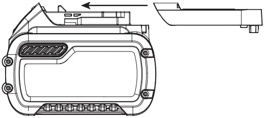 ………………….Class II Construction (double insulated)
- no…………………..no load speed
- n…………………….rated speed
 ………………….earthing terminal
 …………………safety alert symbol
 …………………visible radiation
 …………………avoid staring at light
 …………………wear respiratory protection
 …………………wear eye protection
 …………………wear hearing protection
 …………………read all documentation
- IPXX……………….. IP symbol
BATTERIES AND CHARGERS
The battery pack is not fully charged out of the carton. Before using the battery pack and charger, read the safety instructions below and then follow charging procedures outlined. When ordering replacement battery packs, be sure to include the catalog number and voltage.
READ ALL INSTRUCTIONS
Important Safety Instructions for All Battery Packs
![]() WARNING: Read all safety warnings, instructions, and cautionary markings for the battery pack, charger and product. Failure to follow the warnings and instructions may result in electric shock, fire and/or serious injury.
WARNING: Read all safety warnings, instructions, and cautionary markings for the battery pack, charger and product. Failure to follow the warnings and instructions may result in electric shock, fire and/or serious injury.
- Do not charge or use the battery pack in explosive atmospheres, such as in the presence of flammable liquids, gases or dust. Inserting or removing the battery pack from the charger may ignite the dust or fumes.
- When battery pack is not in use, keep it away from other metal objects, like paper clips, coins, keys, nails, screws, or other small metal objects, that can make a connection from one terminal to another. Shorting the battery terminals together may cause burns or a fire.
- NEVER force the battery pack into the charger. DO NOT modify the battery pack in any way to fit into a non-compatible charger as battery pack may rupture causing serious personal injury. Consult the chart at the end of this manual for compatibility of batteries and chargers.
- Charge the battery packs only in DEWALT chargers.
- DO NOT splash or immerse in water or other liquids.
- Do not store or use the tool and battery pack in locations where the temperature may reach or exceed 104 °F (40 °C) (such as outside sheds or metal buildings in summer). For best life store battery packs in a cool, dry location.
NOTE: Do not store the battery packs in a tool with the trigger switch locked on. Never tape the trigger switch in the ON position. - Do not expose battery pack or tool/appliance to fire or excessive temperature. Exposure to fire or temperature above 265 °F (130 °C) may cause explosion.
- Do not incinerate the battery pack even if it is severely damaged or is completely worn out. The battery pack can explode in a fire. Toxic fumes and materials are created when lithium-ion battery packs are burned.
- If battery contents come into contact with the skin, immediately wash area with mild soap and water. If battery liquid gets into the eye, rinse water over the open eye for 15 minutes or until irritation ceases. If medical attention is needed, the battery electrolyte is composed of a mixture of liquid organic carbonates and lithium salts.
- Contents of opened battery cells may cause respiratory irritation. Provide fresh air. If symptoms persist, seek medical attention.
![]() WARNING: Burn hazard. Battery liquid may be flammable if exposed to spark or flame.
WARNING: Burn hazard. Battery liquid may be flammable if exposed to spark or flame.
![]() WARNING: Fire hazard. Never attempt to open the battery pack for any reason. If the battery pack case is cracked or damaged, do not insert into the charger. Do not crush, drop or damage the battery pack. Do not use a battery pack or charger that has received a sharp blow, been dropped, run over or damaged in any way (e.g., pierced with a nail, hit with a hammer, stepped on). Damaged battery packs should be returned to the service center for recycling.
WARNING: Fire hazard. Never attempt to open the battery pack for any reason. If the battery pack case is cracked or damaged, do not insert into the charger. Do not crush, drop or damage the battery pack. Do not use a battery pack or charger that has received a sharp blow, been dropped, run over or damaged in any way (e.g., pierced with a nail, hit with a hammer, stepped on). Damaged battery packs should be returned to the service center for recycling.
Storage Recommendations
- The best storage place is one that is cool and dry, away from direct sunlight and excess heat or cold.
- For long storage, it is recommended to store a fully charged battery pack in a cool dry place out of the charger for optimal results.
NOTE: Battery packs should not be stored completely depleted of charge. The battery pack will need to be recharged before use.
Battery Pack Cleaning Instructions
Dirt and grease may be removed from the exterior of the battery using a cloth or soft non-metallic brush. Do not use water or any cleaning solutions.
Fuel Gauge Battery Packs
Some DEWALT battery packs include a fuel gauge which consists of three green LED lights that indicate the level of charge remaining in the battery pack.
The fuel gauge is an indication of approximate levels of charge remaining in the battery pack according to the following indicators:
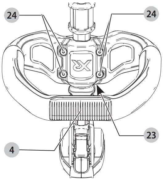 75–100% charged
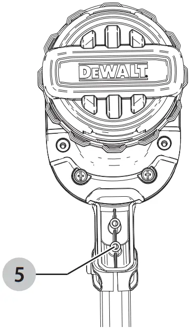 51–74% charged
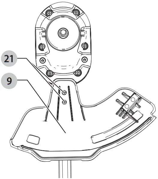 < 50% charged
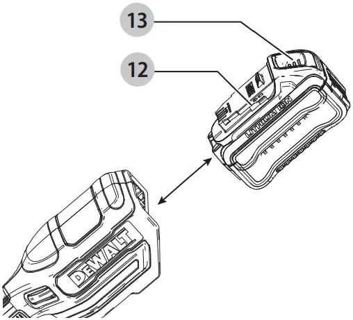 Pack needs to be charged
To actuate the fuel gauge, press and hold the fuel gauge button. A combination of the three green LED lights will illuminate designating the level of charge left. When the level of charge in the battery is below the usable limit, the fuel gauge will not illuminate and the battery will need to be recharged.
NOTE: The fuel gauge is only an indication of the charge left on the battery pack. It does not indicate tool functionality and is subject to variation based on product components, temperature and end-user application.
For more information regarding fuel gauge battery packs, please contact 1-800-4-DEWALT (1-800-433-9258) or visit our website www.dewalt.com.
Transportation
![]() WARNING: Fire hazard. Do not store or carry the battery pack so that metal objects can contact exposed battery terminals. For example, do not place the battery pack in aprons, pockets, tool boxes, product kit boxes, drawers, etc., with loose nails, screws, keys, etc. Transporting batteries can possibly cause fires if the battery terminals inadvertently come in contact with conductive materials such as keys, coins, hand tools and the like. The US Department of Transportation Hazardous Material Regulations (HMR) actually prohibit transporting batteries in commerce or on airplanes in carry-on baggage UNLESS they are properly protected from short circuits. So when transporting individual battery packs, make sure that the battery terminals are protected and well insulated from materials that could contact them and cause a short circuit.
WARNING: Fire hazard. Do not store or carry the battery pack so that metal objects can contact exposed battery terminals. For example, do not place the battery pack in aprons, pockets, tool boxes, product kit boxes, drawers, etc., with loose nails, screws, keys, etc. Transporting batteries can possibly cause fires if the battery terminals inadvertently come in contact with conductive materials such as keys, coins, hand tools and the like. The US Department of Transportation Hazardous Material Regulations (HMR) actually prohibit transporting batteries in commerce or on airplanes in carry-on baggage UNLESS they are properly protected from short circuits. So when transporting individual battery packs, make sure that the battery terminals are protected and well insulated from materials that could contact them and cause a short circuit.
NOTE: Li-ion batteries should not be put in checked baggage.
The RBRC® Seal
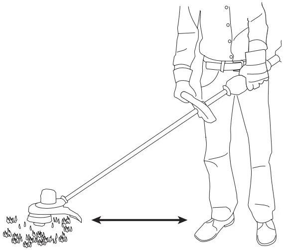
The RBRC® (Rechargeable Battery Recycling Corporation) Seal on the nickel cadmium, nickel metal hydride or lithiumion batteries (or battery packs) indicates that the costs to recycle these batteries (or battery packs) at the end of their useful life have already been paid by DEWALT. In some areas, it is illegal to place spent nickel cadmium, nickel metal hydride or lithium-ion batteries in the trash or municipal solid waste stream and the Call 2 Recycle® program provides an environmentally conscious alternative.
Call 2 Recycle, Inc., in cooperation with DEWALT and other battery users, has established the program in the United States and Canada to facilitate the collection of spent nickel cadmium, nickel metal hydride or lithium-ion batteries. Help protect our environment and conserve natural resources by returning the spent nickel cadmium, nickel metal hydride or lithium-ion batteries to an authorized DEWALT service center or to your local retailer for recycling. You may also contact your local recycling center for information on where to drop off the spent battery. RBRC® is a registered trademark of Call 2 Recycle, Inc.
Shipping the DEWALT FLEXVOLT™ Battery
The DEWALT FLEXVOLT™ battery has two modes: Use and Shipping.
Use Mode: When the FLEXVOLT™ battery stands alone or is in a DEWALT 20V Max* product, it will operate as a 20V Max* battery. When the FLEXVOLT™ battery is in a 60V Max* or a 120V Max* (two 60V Max* batteries) product, it will operate as a 60V Max* battery.
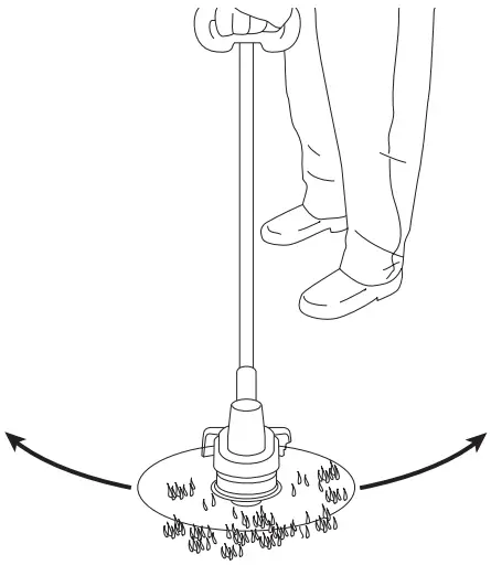 Shipping Mode: When the cap is attached to the FLEXVOLT™ battery, the battery is in Shipping Mode. Strings of cells are electrically disconnected within the pack resulting in three batteries with a lower Watt hour (Wh) rating as compared to one battery with a higher Watt hour rating. This increased quantity of three batteries with the lower Watt hour rating can exempt the pack from certain shipping regulations that are imposed upon the higher Watt hour batteries.
The battery label indicates two Watt hour ratings (see example). Depending on how the battery is shipped, the appropriate Watt hour rating must be used to determine the applicable shipping requirements. If utilizing the shipping cap, the pack will be considered 3 batteries at the Watt hour rating indicated for “Shipping”. If shipping without the cap or in a tool, the pack will be considered one battery at the Watt hour rating indicated next to “Use”.
- Example of Use and Shipping Label Marking
- USE: 120 Wh Shipping: 3 x 40 Wh
For example, Shipping Wh rating might indicate 3 x 40 Wh, meaning 3 batteries of 40 Watt hours each. The Use Wh rating might indicate 120 Wh (1 battery implied).
Important Safety Instructions for All Battery Chargers
![]() WARNING: Read all safety warnings, instructions, and cautionary markings for the battery pack, charger and product. Failure to follow the warnings and instructions may result in electric shock, fire and/or serious injury.
WARNING: Read all safety warnings, instructions, and cautionary markings for the battery pack, charger and product. Failure to follow the warnings and instructions may result in electric shock, fire and/or serious injury.
- DO NOT attempt to charge the battery pack with any chargers other than a DEWALT charger. DEWALT chargers and battery packs are specifically designed to work together.
- These chargers are not intended for any uses other than charging DEWALT rechargeable batteries.
Any other uses may result in risk of fire, electric shock or electrocution. - Do not expose the charger to rain or snow.
- Pull by the plug rather than the cord when disconnecting the charger. This will reduce the risk of damage to the electric plug and cord.
- Make sure that the cord is located so that it will not be stepped on, tripped over or otherwise subjected to damage or stress.
- Do not use an extension cord unless it is absolutely necessary. Use of improper extension cord could result in risk of fire, electric shock or electrocution.
- When operating a charger outdoors, always provide a dry location and use an extension cord suitable for outdoor use. Use of a cord suitable for outdoor use reduces the risk of electric shock.
- An extension cord must have adequate wire size (AWG or American Wire Gauge) for safety. The smaller the gauge number of the wire, the greater the capacity of the cable, that is, 16 gauge has more capacity than 18 gauge. An undersized cord will cause a drop in line voltage resulting in loss of power and overheating. When using more than one extension to make up the total length, be sure each individual extension contains at least the minimum wire size. The following table shows the correct size to use depending on cord length and nameplate ampere rating. If in doubt, use the next heavier gauge. The lower the gauge number, the heavier the cord.
Minimum Gauge for Cord Sets
| Volts | Total Length of Cord in Feet (meters) | ||||
| 120V | 25 (7.6) | 50 (15.2) | 100 (30.5) | 150 (45.7) | |
| 240V | 50 (15.2) | 100 (30.5) | 200 (61.0) | 300 (91.4) | |
| Ampere Rating | American Wire Gauge | ||||
| More Than | Not More Than | ||||
| 0 | 6 | 18 | 16 | 16 | 14 |
| 6 | 10 | 18 | 16 | 14 | 12 |
| 10 | 12 | 16 | 16 | 14 | 12 |
| 12 | 16 | 14 | 12 | Not Recommended | |
![]() WARNING: If the plug or power cord is damaged, it must be replaced by the manufacturer or its representative or by an equally qualified person to avoid danger.
WARNING: If the plug or power cord is damaged, it must be replaced by the manufacturer or its representative or by an equally qualified person to avoid danger.
- Do not place any object on top of the charger or place the charger on a soft surface that might block the ventilation slots and result in excessive internal heat. Place the charger in a position away from any heat source. The charger is ventilated through slots in the top and the bottom of the housing.
- Do not operate the charger with a damaged cord or plug–have them replaced immediately.
- Do not operate the charger if it has received a sharp blow, been dropped or otherwise damaged in any way. Take it to an authorized service center.
- Do not disassemble the charger; take it to an authorized service center when service or repair is required. Incorrect reassembly may result in a risk of electric shock, electrocution or fire.
- Disconnect the charger from the outlet before attempting any cleaning. This will reduce the risk of electric shock. Removing the battery pack will not reduce this risk.
- NEVER attempt to connect 2 chargers together.
- The charger is designed to operate on standard 120V household electrical power. Do not attempt to use it on any other voltage. This does not apply to the vehicular charger.
![]() WARNING: Shock hazard. Do not allow any liquid to get inside the charger. Electric shock may result.
WARNING: Shock hazard. Do not allow any liquid to get inside the charger. Electric shock may result.
![]() WARNING: Burn hazard. Do not submerge the battery pack in any liquid or allow any liquid to enter the battery pack. Never attempt to open the battery pack for any reason. If the plastic housing of the battery pack breaks or cracks, return to a service center for recycling.
WARNING: Burn hazard. Do not submerge the battery pack in any liquid or allow any liquid to enter the battery pack. Never attempt to open the battery pack for any reason. If the plastic housing of the battery pack breaks or cracks, return to a service center for recycling.
![]() CAUTION: Burn hazard. To reduce the risk of injury, charge only DEWALT rechargeable battery packs. Other types of batteries may overheat and burst resulting in personal injury and property damage.
CAUTION: Burn hazard. To reduce the risk of injury, charge only DEWALT rechargeable battery packs. Other types of batteries may overheat and burst resulting in personal injury and property damage.
![]() CAUTION: Under certain conditions, with the charger plugged into the power supply, the charger can be shorted by foreign material. Foreign materials of a conductive nature, such as, but not limited to, grinding dust, metal chips, steel wool, aluminum foil or any buildup of metallic particles should be kept away from the charger cavities. Always unplug the charger from the power supply when there is no battery pack in the cavity. Unplug the charger before attempting to clean.
CAUTION: Under certain conditions, with the charger plugged into the power supply, the charger can be shorted by foreign material. Foreign materials of a conductive nature, such as, but not limited to, grinding dust, metal chips, steel wool, aluminum foil or any buildup of metallic particles should be kept away from the charger cavities. Always unplug the charger from the power supply when there is no battery pack in the cavity. Unplug the charger before attempting to clean.
Charging a Battery
NOTE: To ensure maximum performance and life of lithiumion battery packs, charge the battery pack fully before first use.
- Plug the charger into an appropriate outlet before inserting battery pack.
- Connect the charger and battery pack, making sure the battery is fully seated. The (charging) light will blink continuously indicating that the charging process has started.
- The completion of charge will be indicated by the light remaining ON continuously. The battery pack is fully charged and may be removed and used at this time or left in the charger.
NOTE: To remove the battery pack, some chargers require the battery pack release button to be pressed.
| Indicators | ||
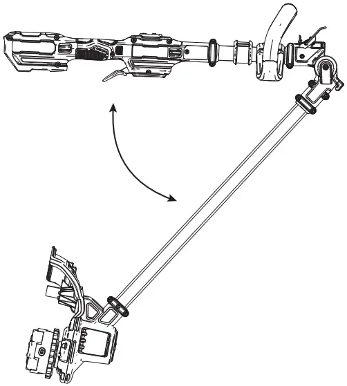 |
Charging |  |
 |
Fully Charged |  |
| Hot/Cold Pack Delay* | ||
DCB107, DCB112, DCB113, DCB115, DCB118, DCB132: The red light will continue to blink, but a yellow indicator light will be illuminated during this operation. Once the battery pack has reached an appropriate temperature, the yellow light will turn off and the charger will resume the charging procedure. A charger will not charge a faulty battery pack. The charger refusing to light could indicate a problem with the charger or a faulty battery pack.
NOTE: If the charger refuses to light, take the charger and battery pack to be tested at an authorized service center.
Leaving the Battery Pack In the Charger
The charger and battery pack can be left connected with the charge indicator showing pack charged.
Hot/Cold Pack Delay
When the charger detects a battery pack that is too hot or too cold, it automatically starts a Hot/Cold Pack Delay, suspending charging until the battery pack has reached an appropriate temperature. The charger then automatically switches to the pack charging mode. This feature ensures maximum battery pack life.
A cold battery pack may charge at a slower rate than a warm battery pack.
The DCB118 charger is equipped with an internal fan designed to cool the battery pack. The fan will turn on automatically when the battery pack needs to be cooled.
Never operate the charger if the fan does not operate properly or if ventilation slots are blocked. Do not permit foreign objects to enter the interior of the charger.
Electronic Protection System
Li-Ion tools are designed with an Electronic Protection System that will protect the battery pack against overloading, overheating or deep discharge.
The tool will automatically turn off if the Electronic Protection System engages. If this occurs, place the lithiumion battery pack on the charger until it is fully charged.
Important Charging Notes
- Longest life and best performance can be obtained if the battery pack is charged when the air temperature is between 65 °F – 75 °F (18 °C–24 °C). DO NOT charge when the battery pack is below +40 °F (+4.5 °C), or above +104 °F (+40 °C). This is important and will prevent serious damage to the battery pack.
- The charger and battery pack may become warm to the touch while charging. This is a normal condition, and does not indicate a problem. To facilitate the cooling of the battery pack after use, avoid placing the charger or battery pack in a warm environment such as in a metal shed or an uninsulated trailer.
- If the battery pack does not charge properly:
a. Check operation of receptacle by plugging in a lamp or other appliance;
b. Check to see if receptacle is connected to a light switch which turns power off when you turn out the lights;
c. Move the charger and battery pack to a location where the surrounding air temperature is approximately 65 °F–75 °F (18 °C–24 °C);
d. If charging problems persist, take the tool, battery pack and charger to your local service center. - The battery pack should be recharged when it fails to produce sufficient power on jobs which were easily done previously. DO NOT CONTINUE to use under these conditions. Follow the charging procedure. You may also charge a partially used pack whenever you desire with no adverse effect on the battery pack.
- Foreign materials of a conductive nature such as, but not limited to, grinding dust, metal chips, steel wool, aluminum foil, or any buildup of metallic particles should be kept away from charger cavities. Always unplug the charger from the power supply when there is no battery pack in the cavity. Unplug the charger before attempting to clean.
- Do not freeze or immerse the charger in water or any other liquid.
Charger Cleaning Instructions
![]() WARNING: Shock hazard. Disconnect the charger from the AC outlet before cleaning. Dirt and grease may be removed from the exterior of the charger using a cloth or soft non-metallic brush. Do not use water or any cleaning solutions.
WARNING: Shock hazard. Disconnect the charger from the AC outlet before cleaning. Dirt and grease may be removed from the exterior of the charger using a cloth or soft non-metallic brush. Do not use water or any cleaning solutions.
Wall Mounting
DCB107, DCB112, DCB113, DCB115, DCB118, DCB132 These chargers are designed to be wall mountable or to sit upright on a table or work surface. If wall mounting, locate the charger within reach of an electrical outlet, and away from a corner or other obstructions which may impede air flow. Use the back of the charger as a template for the location of the mounting screws on the wall. Mount the charger securely using drywall screws (purchased separately) at least 1” (25.4 mm) long, with a screw head diameter of 0.28–0.35” (7–9 mm), screwed into wood to an optimal depth leaving approximately 7/32” (5.5 mm) of the screw exposed. Align the slots on the back of the charger with the exposed screws and fully engage them in the slots.
Intended Use
- This string trimmers is designed for professional trimming applications. This product is not an edger and is not intended to be used for edging.
- DO NOT use under wet conditions or in presence of flammable liquids or gases.
- DO NOT let children come into contact with the tool. Supervision is required when inexperienced operators use this tool.
ASSEMBLY AND ADJUSTMENTS
![]() WARNING: To reduce the risk of serious personal injury, turn unit off and remove the battery pack before making any adjustments or removing/installing attachments or accessories. An accidental start-up can cause injury.
WARNING: To reduce the risk of serious personal injury, turn unit off and remove the battery pack before making any adjustments or removing/installing attachments or accessories. An accidental start-up can cause injury.
Extending and Folding the Pole
![]() WARNING: To reduce the risk of injury, do not operate the unit while folded. The unit must be fully extended and the pole clasp secured before the battery is inserted. Remove battery before folding the unit. Fold unit completely until it locks in place.
WARNING: To reduce the risk of injury, do not operate the unit while folded. The unit must be fully extended and the pole clasp secured before the battery is inserted. Remove battery before folding the unit. Fold unit completely until it locks in place.
- To lock pole into straight use position, first ensure battery has been removed. Then flip up the locking lever 6 rotate pole latch 7 forward and place the pole clasp 8 over the clasp catch 20 . Rotate the pole latch 7 backwards until it locks securely into position. Check the locking lever to make sure it is properly locked in place.
- To fold the pole for storage or transportation, first ensure battery has been removed. Then flip up the locking lever 17 , rotate pole latch 18 forward and lift the pole clasp 19 up and over the clasp catch 20 . Fold the pole completely until the guard 9 securely locks into place over the rear of the battery housing 11.
Fig. B

Attaching the Auxiliary Handle
- Place the auxiliary handle 4 on top of the handle base 23 so the upper trimmer pole 15 is between them.
- Hold the auxiliary handle in place and slide the handle bolts 24 into the handle from the top, threading them into the handle base.
- Tighten the handle bolts with the supplied hex wrench. Ensure the handle is securely attached.
Fig. C

Attaching Guard
![]() WARNING: Never remove the guard. Damage or personal injury could result.
WARNING: Never remove the guard. Damage or personal injury could result.
![]() WARNING: NEVER OPERATE APPLIANCE WITHOUT GUARD FIRMLY IN PLACE.
WARNING: NEVER OPERATE APPLIANCE WITHOUT GUARD FIRMLY IN PLACE.
The guard must always be properly attached on the appliance to protect the user.
- Assemble the guard 9 to the motor housing 5.
- Using a crosshead screwdriver, insert the 2 guard screws 21 and tighten securely.
NOTE: An extended coverage guard is available (sold separately) for extra coverage if desired. Use replacement guard Part Number N776035.
Fig. D

Fig. E

OPERATION
![]() WARNING: To reduce the risk of serious personal injury, turn unit off and remove the battery pack before making any adjustments or removing/installing attachments or accessories. An accidental start-up can cause injury.
WARNING: To reduce the risk of serious personal injury, turn unit off and remove the battery pack before making any adjustments or removing/installing attachments or accessories. An accidental start-up can cause injury.
Installing and Removing the Battery Pack
NOTE: For best results, make sure your battery pack is fully charged.
To install the battery pack 12 into the tool handle, align the battery pack with the rails inside the tool’s handle and slide it into the handle until the battery pack is firmly seated in the tool and ensure that it does not disengage. To remove the battery pack from the tool, press the release button 13 and firmly pull the battery pack out of the tool handle. Insert it into the charger as described in the charger section of this manual
Fig. F

Proper Hand Position
![]() WARNING: To reduce the risk of serious personal injury, ALWAYS use proper hand position as shown.
WARNING: To reduce the risk of serious personal injury, ALWAYS use proper hand position as shown.
![]() WARNING: To reduce the risk of serious personal injury, ALWAYS hold securely in anticipation of a sudden reaction.
WARNING: To reduce the risk of serious personal injury, ALWAYS hold securely in anticipation of a sudden reaction.
![]() WARNING: Always use proper eye protection that conforms to ANSI Z87.1 (CAN/CSA Z94.3) while operating this appliance.
WARNING: Always use proper eye protection that conforms to ANSI Z87.1 (CAN/CSA Z94.3) while operating this appliance.
![]() WARNING: Remove the battery before making any assembly, adjustments, or changing accessories. Such preventive safety measures reduce the risk of starting the TRIMMER accidentally.
WARNING: Remove the battery before making any assembly, adjustments, or changing accessories. Such preventive safety measures reduce the risk of starting the TRIMMER accidentally.
![]() CAUTION: Before you begin trimming, only use the appropriate type of cutting line.
CAUTION: Before you begin trimming, only use the appropriate type of cutting line.
![]() CAUTION: Inspect area to be trimmed and remove any wire, cord, or string-like objects which could become entangled in the rotating line or spool. Be particularly careful to avoid any wire which might be bent outwardly into the path of the appliance, such as barbs at the base of a chain link fence.
CAUTION: Inspect area to be trimmed and remove any wire, cord, or string-like objects which could become entangled in the rotating line or spool. Be particularly careful to avoid any wire which might be bent outwardly into the path of the appliance, such as barbs at the base of a chain link fence.
Proper hand position requires one hand on the primary handle 14 and one hand on the auxiliary handle 4.
Fig. G

Switching Trimmer On and Off
- To turn the appliance on, squeeze the lock-off button 2 and then the variable speed trigger 1.
- To turn the appliance off, release the variable speed trigger and the lock-off button.
![]() WARNING: Never attempt to lock the trigger in the on position.
WARNING: Never attempt to lock the trigger in the on position.
Speed Control Switch
This string trimmer gives you the choice to operate at a more efficient speed to extend the runtime for larger jobs, or accelerate the trimmer speed for high-performance cutting. To extend runtime, push the speed control switch 3 forward toward the Auxiliary handle 4 into the “LO” position. This mode is best for larger projects that require more time to complete. To accelerate the trimmer, pull the speed control switch back toward the battery housing 11 into the “HI” position. This mode is best to cut through heavier growth and for applications that need higher RPM.
NOTE: When in “HI” mode, runtime will be decreased as compared to when trimmer is in “LO” mode.
Trimming
- With the trimmer on, angle it and swing side to side as shown in Fig. H.
- Maintain a minimum distance of 24″ (610 mm) between the guard and your feet as shown in Fig. I.
![]() WARNING: Keep the rotating string roughly parallel with the ground (tilted no more than 30 degrees). This trimmer is not an edger. DO NOT TILT the trimmer so that the string is spinning near a right angle to the ground. Flying debris can cause serious injury.
WARNING: Keep the rotating string roughly parallel with the ground (tilted no more than 30 degrees). This trimmer is not an edger. DO NOT TILT the trimmer so that the string is spinning near a right angle to the ground. Flying debris can cause serious injury.
Fig. H

Fig. I

Bump Feed Trimmer Line Feed
Your trimmer uses 0.080″ (2.0 mm) diameter nylon line. Cutting line will wear faster and require more feeding if the cutting is done along sidewalks or other abrasive surfaces or heavier weeds are being cut.
As you use the trimmer, the string will get shorter due to wear. Gently bump the trimmer on the ground while running at normal speed and the line will feed.
NOTE: Extending nylon line beyond the 14″ (355 mm) swath will negatively affect performance, runtime, and the life of the trimmer due to potential of damaging motor. Doing so may void the warranty.
Helpful Cutting Tips
- Use the tip of the string to do the cutting; do not force string head into uncut grass.
- Wire and picket fences cause extra string wear, even breakage. Stone and brick walls, curbs, and wood may wear string rapidly.
- Do not allow spool cap to drag on ground or other surfaces.
- In long growth, cut from the top down and do not exceed 12″ (304.8 mm) high.
- Keep trimmer tilted toward the area being cut; this is the best cutting area.
- The trimmer cuts when passing the unit from the left to right. This will avoid throwing debris at the operator.
- Avoid trees and shrubs. Tree bark, wood moldings, siding, and fence posts can easily be damaged by the string.
MAINTENANCE
![]() WARNING: To reduce the risk of serious personal injury, turn unit off and remove the battery pack before making any adjustments or removing/installing attachments or accessories. An accidental start-up can cause injury.
WARNING: To reduce the risk of serious personal injury, turn unit off and remove the battery pack before making any adjustments or removing/installing attachments or accessories. An accidental start-up can cause injury.
Maintenance Treatments (Fig. J)
- Keep the air intake slots 30 clean to avoid overheating (Fig. J).
- Your trimmer line can dry out over time. To keep your line in top condition, store spare line in a plastic, sealable bag with a tablespoon of water.
- Plastic parts may be cleaned by using a mild soap and a damp rag.
- The line cutter on the edge of the guard can dull over time. It is recommended you periodically touch-up the sharpness of the blade with a file.
Fig. J

Replacement Accessories
![]() WARNING: To reduce the risk of serious personal injury, turn appliance off and remove battery before making any adjustments or removing/installing attachments or accessories.
WARNING: To reduce the risk of serious personal injury, turn appliance off and remove battery before making any adjustments or removing/installing attachments or accessories.
![]() WARNING: The use of any accessory not recommended by DEWALT for use with this appliance could be hazardous.
WARNING: The use of any accessory not recommended by DEWALT for use with this appliance could be hazardous.
![]() WARNING: Do not use any blades, or any accessory or attachment other than those recommended by DEWALT on this trimmer. Serious injury or product damage may result.
WARNING: Do not use any blades, or any accessory or attachment other than those recommended by DEWALT on this trimmer. Serious injury or product damage may result.
Use DEWALT replacement line Model No. DWO1DT801 or DWO1DT802.
When replacing the line, use only .080″ (2.0 mm) diameter line (Model No. DWO1DT801 or DWO1DT802 are is recommended). Other sizes may degrade performance or cause damage to the trimmer.
Reloading the Cutting Line
![]() WARNING: To reduce the risk of serious personal injury, turn unit off and remove the battery pack before making any adjustments or removing/installing attachments or accessories, when replacing line, or prior to cleaning. An accidental start-up can cause injury.
WARNING: To reduce the risk of serious personal injury, turn unit off and remove the battery pack before making any adjustments or removing/installing attachments or accessories, when replacing line, or prior to cleaning. An accidental start-up can cause injury.
![]() CAUTION: Use only DEWALT replacement spools and line. Using any other manufacturer’s line can reduce performance, damage the trimmer or cause personal injury.
CAUTION: Use only DEWALT replacement spools and line. Using any other manufacturer’s line can reduce performance, damage the trimmer or cause personal injury.
Your trimmer uses 0.080″ (2.0 mm) diameter line that is spiral-shaped with smooth round edges. Do not use other size lines. This can degrade performance, cause damage to the unit or injury.
![]() CAUTION: To avoid appliance damage, if the cutting line protrudes beyond the trimming blade, cut it off so that it just reaches the blade.
CAUTION: To avoid appliance damage, if the cutting line protrudes beyond the trimming blade, cut it off so that it just reaches the blade.
Use only DEWALT replacement line.
- Remove battery.
- Cut a max of 20′ (6 m) length of of 0.080″ (2.0 mm) trimmer line.
- Align spool housing eyelets 26 with the arrow 27 on the spool grip cover 29 as shown in Fig. K.
- Thread one end of the trimmer line through an eyelet. Guide the line through to the second eyelet and continue to pull the line through until there are equal lengths of string on each side of the spool housing as shown in Fig. L.
- Secure the spool cap from moving with one hand. Using your other hand, wind the string onto the spool by rotating the spool grip cover counterclockwise. Continue winding until 5″ (130 mm) of string remain on each side of the spool housing.
Fig. K

Fig. L

Fig. M

Cleaning
![]() WARNING: Blow dirt and dust out of all air vents with clean, dry air at least once a week. To minimize the risk of eye injury, always wear ANSI Z87.1 approved eye protection when performing this procedure.
WARNING: Blow dirt and dust out of all air vents with clean, dry air at least once a week. To minimize the risk of eye injury, always wear ANSI Z87.1 approved eye protection when performing this procedure.
![]() WARNING: Never use solvents or other harsh chemicals for cleaning the non-metallic parts of the tool. These chemicals may weaken the plastic materials used in these parts. Use a cloth dampened only with water and mild soap. Never let any liquid get inside the tool; never immerse any part of the tool into a liquid.
WARNING: Never use solvents or other harsh chemicals for cleaning the non-metallic parts of the tool. These chemicals may weaken the plastic materials used in these parts. Use a cloth dampened only with water and mild soap. Never let any liquid get inside the tool; never immerse any part of the tool into a liquid.
Accessories
![]() WARNING: Since accessories, other than those offered by DEWALT, have not been tested with this product, use of such accessories with this tool could be hazardous. To reduce the risk of injury, only DEWALT recommended accessories should be used with this product.
WARNING: Since accessories, other than those offered by DEWALT, have not been tested with this product, use of such accessories with this tool could be hazardous. To reduce the risk of injury, only DEWALT recommended accessories should be used with this product.
Recommended accessories for use with your tool are available at extra cost from your local dealer or authorized service center. If you need assistance in locating any accessory, please contact DEWALT call 1-800-4-DEWALT (1-800-433-9258) or visit our website: www.dewalt.com.
Replacement Accessories
Replacing Spool Assembly (Fig. A, N)
- Rotate the spool housing 10 until the hole 31 in the spindle plate aligns with notch 32 in the motor housing. Insert a screwdriver through the notch and into the hole, to prevent the spindle from turning.
- Unscrew and remove the spool housing by turning the spool grip cover 29 clockwise.
NOTE: Do not try to remove the spool by turning the spool housing 28. - Remove spindle plate 34 before installing a new spool.
Remove any dirt and grass from the motor housing and spindle plate. - Install spindle plate 34 onto the spindle 33, so the double D shaped retaining nut on the spindle sits inside the base of the spindle plate.
- Align the spindle plate hole and notch, insert a screwdriver back into the hole and thread the new spool housing counterclockwise. Securely tighten the new spool housing onto the spindle 33.
Fig. N

Replacing Guard (Fig. O)
An extended coverage guard is available (sold separately) for extra coverage if desired. Use DEWALT replacement guard Part Number N496261.
![]() WARNING: Never operate appliance without guard firmly in place.
WARNING: Never operate appliance without guard firmly in place.
- Remove the 2 guard screws 21.
- Attach the new guard as described in the Attaching Guard section.
Fig. O

Folding for Storage or Transportation (Fig. P)
The string trimmer can be folded for storage or transportation. To put the string trimmer in the folded position, please refer to Extending and Folding the Pole.
Fig. P

Repairs
The charger and battery pack are not serviceable. There are no serviceable parts inside the charger or battery pack.
![]() WARNING: To assure product SAFETY and RELIABILITY, repairs, maintenance and adjustment (including brush inspection and replacement, when applicable) should be performed by a DEWALT factory service center or a DEWALT authorized service center. Always use identical replacement parts.
WARNING: To assure product SAFETY and RELIABILITY, repairs, maintenance and adjustment (including brush inspection and replacement, when applicable) should be performed by a DEWALT factory service center or a DEWALT authorized service center. Always use identical replacement parts.
Register Online
- Thank you for your purchase. Register your product now for:
WARRANTY SERVICE
- Registering your product will help you obtain more efficient warranty service in case there is a problem with your product.
- CONFIRMATION OF OWNERSHIP: In case of an insurance loss, such as fire, flood or theft, your registration of ownership will serve as your proof of purchase.
- FOR YOUR SAFETY: Registering your product will allow us to contact you in the unlikely event a safety notification is required under the Federal Consumer Safety Act.
- Register online at www.dewalt.com
Three Year Limited Warranty
DEWALT will repair or replace, without charge, any defects due to faulty materials or workmanship for three years from the date of purchase (two years for batteries). This warranty does not cover part failure due to normal wear or tool abuse. For further detail of warranty coverage and warranty repair information, visit www.dewalt.com or call 1-800-4-DEWALT (1-800-433-9258). This warranty does not apply to accessories or damage caused where repairs have been made or attempted by others. THIS LIMITED WARRANTY IS GIVEN IN LIEU OF ALL OTHERS, INCLUDING THE IMPLIED WARRANTY OF MERCHANTABILITY AND FITNESS FOR A PARTICULAR PURPOSE, AND EXCLUDES ALL INCIDENTAL OR CONSEQUENTIAL DAMAGES. Some states do not allow limitations on how long an implied warranty lasts or the exclusion or limitation of incidental or consequential damages, so these limitations may not apply to you. This warranty gives you specific legal rights and you may have other rights which vary in certain states or provinces.
In addition to the warranty DEWALT tools are covered by our:
1 YEAR FREE SERVICE
DEWALT will maintain the tool and replace worn parts caused by normal use, for free, any time during the first year after purchase.
2 YEARS FREE SERVICE ON DEWALT BATTERY PACKS
DC9071, DC9091, DC9096, DC9182, DC9280, DC9360, DCB120, DCB122, DCB124, DCB127, DCB201, DCB203BT, DCB207, DCB361
3 YEARS FREE SERVICE ON DEWALT BATTERY PACKS
DCB200, DCB203, DCB204, DCB204BT, DCB205, DCB205BT, DCB206, DCB230, DCB606, DCB609, DCB612
NOTE: Battery warranty voided if the battery pack is tampered with in any way. DEWALT is not responsible for any injury caused by tampering and may prosecute warranty fraud to the fullest extent permitted by law.
90 DAY MONEY BACK GUARANTEE
If you are not completely satisfied with the performance of your DEWALT Power Tool or Nailer for any reason, you can return it within 90 days from the date of purchase with a receipt for a full refund – no questions asked.
LATIN AMERICA: This warranty does not apply to products sold in Latin America. For products sold in Latin America, see country specific warranty information contained in the packaging, call the local company or see website for warranty information.
FREE WARNING LABEL REPLACEMENT: If your warning labels become illegible or are missing, call 1-800-4-DEWALT (1-800-433-9258) for a free replacement.
Compatible battery packs and chargers
| 20V Max* Li-Ion | Battery Packs | DCB200, DCB201, DCB203, DCB204, DCB204BT**, DCB205, DCB205BT**, DCB206, DCB208, DCB230, DCB240 |
| Chargers | DCB101, DCB103, DCB104, DCB107, DCB112, DCB113, DCB115, DCB118, DCB132 |
| 60V Max* Li-Ion | Battery Packs | DCB606, DCB609, DCB612 |
| Chargers | DCB101, DCB103, DCB104, DCB107, DCB112, DCB113, DCB115, DCB118, DCB132 |
Maximum initial battery voltage (measured without a workload) is 12, 20, 60 or 120 volts. Nominal voltage is 10.8, 18, 54 or 108.
(120V Max* is based on using 2 DEWALT 60V Max* lithium-ion batteries combined.)
BT – Bluetooth®
NOTE: The Bluetooth® word mark and logos are registered trademarks owned by the Bluetooth®, SIG, Inc. and any use of such marks by DEWALT is under license. Other trademarks and trade names are those of their respective owners.
![]() WARNING: Use of any other battery packs may create a risk of injury and fire.
WARNING: Use of any other battery packs may create a risk of injury and fire.
DEWALT Industrial Tool Co. 701 East Joppa Road, Towson, MD 21286
Copyright © 2019
The following are trademarks for one or more DEWALT power tools: the yellow and black color scheme, the “D” shaped air intake grill, the array of pyramids on the handgrip, the kit box configuration, and the array of lozenge-shaped humps on the surface of the tool.
SPECIFICATION
| Product Specifications | Description |
|---|---|
| Model Number | DCST922 |
| Product Type | String Trimmer |
| Power Source | Battery (20V Max*) |
| Line Diameter | 0.080 inches (2.0 mm) |
| Usage | Outdoor |
| Safety Alert Symbols | Danger, Warning, Caution, Notice |
| Additional Safety Warnings | Includes warnings on dress, safe operation, and maintenance |
| Manufacturer | DEWALT |
| Manufacturer Contact Information | 1-800-4-DEWALT |
What is the difference between the DCST922 and the DCST920?
The DCST922 is a 20V Max* trimmer, while the DCST920 is a 20V Max* edger.
What is the difference between the DCST922 and the DCST925?
The DCST922 is a 20V Max* trimmer, while the DCST925 is a 20V Max* edger.
How do I use the battery pack on my string trimmer?
To install or remove the battery pack from your string trimmer, simply slide it into position and then release it from its housing. To charge your battery pack, simply slide it into position and then plug in your charger. The battery pack can be charged in two ways. You can either plug it into your charger or you can use your string trimmer as a power source to charge it. Simply plug your charger into an outlet and then plug your string trimmer into your charger. Your battery pack will begin to charge automatically
How do I know when my battery needs to be recharged?
When you are using your string trimmer, if you notice that you are having to give it more effort than normal to get through weeds or grass, then it may be time to recharge your battery pack. If you notice that you are having to give it even more effort than normal, then you may need to replace your battery pack with a new one.
What kind of maintenance does my string trimmer require?
Your string trimmer requires no maintenance for normal operation. However, if you use your string trimmer in wet conditions or if you use it frequently, then you may want to consider cleaning out any debris that has accumulated in or around the spool housing area of your string trimmer. This will help prevent any unnecessary wear on your string trimmer and will also help extend its life span.
Is the DeWalt dcst922b brushless?
Key Features of the DeWalt DCST922:
Beyond that marquee feature, you’ve still got a string trimmer designed to handle the rigors of home lawn maintenance. This trimmer comes equipped with a brushless motor that reaches speeds up to 6000 RPM. The DeWalt Folding String Trimmer has a respectable 14-inch cutting swath.
How do you Change the line on a DeWalt Trimmer?
Once the cap is off I set it down and then you hold on to this outer ring here with the slots in it and you line up that metal Col with the hole in this plastic head these two line up.
How Good is the DeWalt Cordless Trimmer?
The handle and trigger grip section is also a bit thicker than most, so you might not care for it if you have smaller hands. The overall balance of this string trimmer is excellent. Even though the battery and motor weight are both on the back, it was very easy to maneuver around flower beds and driveway culverts.
What battery does Dewalt trimmer use?
This item uses the 20v battery but recommend a battery with more Ah for longer run time
Are Dewalt batteries interchangeable?
Yes, all of the DEWALT 20V batteries are interchangeable. You can use any of the batteries with any of the chargers in the DEWALT 20V line.
What is the difference between DeWalt 20V MAX and 20V max XR batteries?
The main difference between the two lines is the type of battery each uses. The 20V MAX uses lithium ion batteries, while the 20V XR uses brushless motors and high capacity lithium ion batteries. The 20V MAX is the next line after 18V, and it introduces lithium ion batteries
What size Dewalt trimmer line?
It uses dual 0.080-inch cutting lines on a 13-inch diameter head. This DeWalt battery string trimmer has a straight shaft and weighs 8.5 lbs. It uses dual 0.080-inch cutting lines on a 13-inch diameter head.
What is the DCST922 Instruction Manual for?
The DCST922 Instruction Manual provides safety information and usage instructions for the DEWALT 20V Max* String Trimmer.
What safety alert symbols and words are used in the manual?
The safety alert symbols and words used in the manual are DANGER, WARNING, CAUTION, and NOTICE.
What are the additional safety warnings provided in the manual?
The additional safety warnings provided in the manual include avoiding dangerous environments, dressing properly, using safety glasses, using the right appliance, staying alert, disconnecting the appliance, storing idle appliances indoors, maintaining the appliance with care, checking damaged parts, and more.
What is the importance of reading and understanding all safety instructions and other information contained in the document before using the product?
It is important to read and understand all safety instructions and other information contained in the document before using the product to reduce the risk of injury.
What should be done if the switch trigger does not turn the appliance on or off?
If the switch trigger does not turn the appliance on or off, do not use the appliance. Any appliance that cannot be controlled with the switch trigger is dangerous and must be repaired.
Can any other manufacturer’s line be used with the DEWALT 20V Max* String Trimmer?
No, only DEWALT replacement spools and line should be used. Using any other manufacturer’s line can reduce performance, damage the trimmer, or cause personal injury.
What should be done if the guard or other part is damaged?
Before further use of the appliance, a guard or other part that is damaged should be carefully checked to determine that it will operate properly and perform its intended function. A guard or other part that is damaged should be properly repaired or replaced by an authorized service center unless indicated elsewhere in this manual.
What should be done if the appliance strikes or becomes entangled with a foreign object?
If the appliance strikes or becomes entangled with a foreign object, stop the appliance immediately, check for damage, and have any damage repaired before further operation is attempted. Do not operate with a broken hub or spool.
What size line should be used with the DEWALT 20V Max* String Trimmer?
The DEWALT 20V Max* String Trimmer uses 0.080 inches (2.0 mm) diameter line. Do not use other size lines. This can degrade performance, cause damage to the unit, or cause injury.
DEWALT 20V MAX STRING TRIMMER DCST922
VIDEO


DEWALT 20V Max* String Trimmer DCST922
www.dewalt.com/product/dcst922p1/20v-max-14-folding-string-trimmer
SAFETY INSTRUCTIONS FOR LASERS
 WARNING! Read and understand all instructions.
Failure to follow all instructions listed below may result in electric shock, fire and/or serious personal injury.
SAVE THESE INSTRUCTIONS
Warning! Laser Radiation Exposure. Do not disassemble or modify the laser level. There are no user serviceable part inside. Serious eye injury could result.
Warning! Hazardous Radiation. Use of controls or adjustments or performance of procedures other than those specified herein may result in hazardous radiation exposure.
- Do not operate the laser in explosive atmospheres, such as in the presence of flammable liquids, gases, or dust. Power tools create sparks which may ignite the dust or fumes.
- Use the laser only with the specifically designated batteries. Use of any other batteries may create a risk of fire.
- Store idle laser out of reach of children and other untrained persons. Lasers are dangerous in the hands of untrained users.
- Use only accessories that are recommended by the manufacturer for your model. Accessories that may be suitable for one laser, may create a risk of injury when used on another laser.
- Tool service must be performed only by qualified repair personnel. Service or maintenance performed by unqualified personnel may result in injury. .
- Do not use optical tools such as a telescope or transit to view the laser beam. Serious eye injury could result.
- Do not place the laser in a position which may cause anyone to intentionally or unintentionally stare into the laser beam. Serious eye injury could result.
- Turn the laser off when it is not in use. Leaving the laser on increases the risk of staring into the laser beam.
- Do not disassemble the laser tool. There are no user serviceable parts inside.
- Do not modify the laser in any way. Modifying the tool may result in Hazardous Laser Radiation Exposure.
- Do not operate the laser around children or allow children to operate the laser. Serious eye injury may result.
- Do not remove or deface warning labels. Removing labels increases the risk of exposure to radiation.
- Position the laser securely on a level surface. Damage to the laser or serious injury could result if the laser falls.
Warning! Some dust created by power sanding, sawing, grinding, drilling, and other construction activities contains chemicals known to the State of California to cause cancer, birth defects or other reproductive harm. Some examples of these chemicals are:
- lead from lead-based paints,
- crystalline silica from bricks and cement and other masonry products, and
- arsenic and chromium from chemically-treated lumber.
Your risk from these exposures varies, depending on how often you do this type of work. To reduce your exposure to these chemicals: work in a well ventilated area, and work with approved safety equipment, such as those dust masks that are specially designed to filter out microscopic particles.
Avoid prolonged contact with dust from power sanding, sawing, grinding, drilling, and other construction activities. Wear protective clothing and wash exposed areas with soap and water. Allowing dust to get into your mouth, eyes, or lay on the skin may promote absorption of harmful chemicals.
Warning! Use of this tool can generate and/or disburse dust, which may cause serious and permanent respiratory or other injury. Always use NIOSH/OSHA approved respiratory protection appropriate for the dust exposure. Direct particles away from face and body.
The label on your tool may include the following symbols.
V ………………… volts
mW ……………..milliwatts
………… laser warning
symbol
nm……………….wavelength in
nanometers
II(2)…………….. Class II (2) Laser
Warning Labels
For your convenience and safety, the following label is on your laser.
Caution! Laser radiation – Do not stare into the laser beam. Class II laser product.
Caution! Class II Laser radiation when open do not stare into the beam.
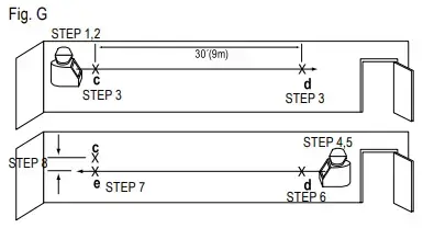
Introduction
The DW088 lasers are self-leveling laser tools that can be used inside and outside for horizontal (level) vertical and plumb alignment projects.
GENERAL SAFETY RULES FOR BATTERY OPERATED TOOLS
Warning! Read and understand all instructions. Failure to follow all instructions listed below may result in electric shock, fire and/or serious personal injury.
Work area
- Keep your work area clean and well lit Cluttered benches and dark areas invite accidents.
- Do not operate power tools in explosive atmospheres, such as in the presence of flammable liquids, gases, or dust. Power tools create sparks which may ignite the dust or fumes.
- Keep bystanders, children, and visitors away while operating a power tool. Distractions can cause you to lose control.
Electrical safety
Use battery operated tool only with the specifically designed batteries. Use of any other batteries may create a risk of fire.
Battery
This tool is powered by three 1.5V AA size batteries.
Note: AR version does not include battery.
To install batteries:
- Lift up the battery compartment cover 1, as shown in Fig.A.
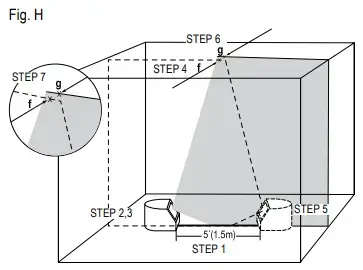
- Insert three fresh AA batteries in the compartment, placing the batteries according to (+) and (–) on the inside of the battery door.
Warning! Batteries can explode, or leak, and can cause injury or fire. To reduce this risk:
- Carefully follow all instructions and warnings on the battery label and package.
- Always insert batteries correctly with regard to polarity (+ and –), marked on the battery and the equipment.
- Do not short battery terminals.
- Do not charge batteries.
- Do not mix old and new batteries. Replace all of them at the same time with new batteries of the same brand and type.
- Remove dead batteries immediately and dispose of per local codes.
- Do not dispose of batteries in fire.
- Keep batteries out of reach of children.
- Remove batteries if the device will not be used for several months.
Personal safety
- Stay alert, watch what you are doing and use common sense when operating a laser tool. Do not use tool while tired or under the influence of drugs, alcohol, or medication. A moment of inattention while operating power tools may result in serious personal injury.
- Do not overreach. Keep proper footing and balance at all times. Proper footing and balance enables better control of the tool in unexpected situations.
- Use safety equipment. Always wear eye protection. Dust mask, non-skid safety shoes, hard hat, or hearing protection may be required for appropriate conditions.
Tool use and care
- Do not use tool if switch does not turn it on or off. Any tool that cannot be controlled with the switch is dangerous and must be repaired.
- Store idle tools out of reach of children and other untrained persons. Tools are dangerous in the hands of untrained users.
- Use only accessories that are recommended by the manufacturer for your model. Accessories that may be suitable for one tool, may become hazardous when used on another tool.
Service
- Tool service must be performed only by qualified repair personnel. Service or maintenance performed by unqualified personnel could result in a risk of injury.
- When servicing a tool, use only identical replacement parts. Follow instructions in the Maintenance section of this manual. Use of unauthorized parts or failure to follow Maintenance Instructions may create a risk of electric shock or injury.
To locate your nearest DeWALT service center call 1–800–4-DeWALT (1–800–433–9258) or go to http://www.DeWALT.com on the Internet.
OPERATING TIPS
- Use only new, high-quality, name brand batteries for best results.
- Ensure batteries are in good working condition. If the low battery red indicator light is flashing, the batteries need replacement.
- To extend battery life, turn laser off when not working with or marking the beam.
- To ensure the accuracy of your work, check to make sure your laser is calibrated often. See Field Calibration Check.
- Before attempting to use the laser, make sure it is positioned securely, on a smooth, flat surface.
- Always mark the center of the beam created by the laser.
- Extreme temperature changes may cause movement of internal parts that can affect accuracy. Check your accuracy often while working. See Field Calibration Check.
- If the laser has been dropped, check to make sure your laser is still calibrated. See Field Calibration Check.
LOW BATTERY INDICATION
The DW088 lasers are equipped with a red indicator light 2, as shown in Fig. B. The red indicator lights are located to the left of the on/off buttons (3, 4).

A flashing red indicator light indicates that the batteries are low and need to be replaced. The laser may continue to operate for a short time while the batteries continue to drain, but the beam(s) will quickly dim. After fresh batteries are installed and the laser is turned on again, the laser beam(s) will return to full brightness and the red indicator light will stay off. (A flashing laser beam is not caused by low batteries; see Out of Tilt Range Indicator.)
OPERATION
TO TURN THE LASERS ON AND OFF (FIg. B)
With the laser off, place it on a flat surface. This model has two ON/OFF buttons, one for a horizontal laser line 3 and one for a vertical laser line 4. Each laser line is powered on by pressing its ON/OFF button. The laser lines can be powered one at a time or at the same time. Pressing the ON/OFF buttons again turns the laser lines off.
USING THE LASERS
The beams are level or plumb as long as the calibration has been checked (see Field Calibration Check) and the laser beam is not flashing (see Out of Tilt Range Indicator).
Out of Tilt Range Indicator (Fig. C, D)
The lasers are designed to self-level. If the laser has been tilted so much that it cannot level itself (average > 4° tilt), it will flash the laser beam (Fig. D). The flashing beam indicates the tilt range has been exceeded and IS NOT LEVEL (OR PLUMB) AND SHOULD NOT BE USED FOR DETERMINING OR MARKING LEVEL (OR PLUMB). Try repositioning the laser on a more level surface.

Using the Lasers with Accessories
The lasers are equipped with a 1/4” x 20 female thread on the bottom of the unit. This thread is to accommodate current or future DeWALT accessories. Only use DeWALT accessories specified for use with this product. Follow the directions included with the accessory.
Caution! The use of any other accessory not recommended for use with this tool could be hazardous.
If you need any assistance in locating any accessory, please contact DeWALT Industrial Tool Co., 701 East Joppa Road, Towson, MD 21286 or call 1–800–4-DeWALT (1–800–433–9258). See our catalog on the World Wide Web at www.DeWALT.com.
Using the Pivot Bracket (Fig. E)
The lasers have a magnetic pivot bracket 5 permanently attached to the units. This bracket allows the unit to be mounted to any upright surface made of steel or iron. Common examples of suitable surfaces include steel framing studs, steel door frames and structural steel beams. The bracket also has a keyhole slot 6 allowing the unit to be hung from a nail or screw on any kind of surface. Position the laser and/or wall mount on a stable surface. Serious personal injury or damage to the laser may result if the laser falls.
Using the Laser with the Wall Mount (Fig. E)
The DW0860 Laser Wall Mount offers more mounting options for the DW088 lasers. The wall mount has a clamp 7 at one end which can be fixed to a wall angle for acoustic ceiling installation. At the other end of the wall mount is a screw hole 8, allowing the wall mount to be attached to any surface with a nail or screw.
Once the wall mount is secured, its steel plate provides a surface to which the magnetic pivot bracket can be attached. The position of the laser can then be fine-tuned by sliding the pivot bracket up or down on the wall mount.
Leveling the Lasers
s long as the lasers are properly calibrated, the lasers are selfleveling. Each laser is calibrated at the factory to find level as long as it is positioned on a flat surface within average ± 4° of level. No manual adjustments must be made.

MAINTENANCE
- To maintain the accuracy of your work, check the laser often to make sure it is properly calibrated. See Field Calibration Check.
- Calibration checks and other maintenance repairs may be performed by DeWALT service centers.
- When not in use, store the laser in the kit box provided. Do not store your laser at temperatures below -5 ºF (-20 ºC) or above 140 ºF (60 ºC).
- Do not store your laser in the kit box if the laser is wet. The laser should be dried first with a soft dry cloth.
CLEANING
Exterior plastic parts may be cleaned with a damp cloth. Although these parts are solvent resistant, NEVER use solvents. Use a soft, dry cloth to remove moisture from the tool before storage.
FIELD CALIBRATION CHECK
Checking Accuracy – Horizontal Beam, Scan Direction (Fig. F)
Checking the horizontal scan calibration of the laser requires two walls 30’ (9 m) apart. It is important to conduct a calibration check using a distance no shorter than the distance of the applications for which the tool will be used.
- Attach the laser to a wall using its pivot bracket. Make sure the laser is facing straight ahead.
- Turn on the laser’s horizontal beam and pivot the laser approximately 45º so that the right-most end of the laser line is striking the opposing wall at a distance of at least 30’ (9 m). Mark the center of the beamo (a).
- Pivot the laser approximately 90º to bring the left-most end of the laser line around to the mark made in Step 2. Mark the center of the beam (b).
- Measure the vertical distance between the marks.
- If the measurement is greater than the values shown below, the laser must be serviced at an authorized service center.
| Distance Between Walls | Allowable Distance Between Marks |
| 30’ (9 m) | 1/8” (3.0 mm) |
| 40’ (12 m) | 5/32” (4.0 mm) |
| 50’ (15 m) | 7/32” (5.0 mm) |

Checking Accuracy – Horizontal Beam, Pitch Direction (Fig. G)
Checking the horizontal pitch calibration of the laser requires a single wall at least 30’ (9 m) long. It is important to conduct a calibration check using a distance no shorter than the distance of the applications for which the tool will be used.
- Attach the laser to one end of a wall using its pivot bracket.
- Turn on the laser’s horizontal beam and pivot the laser toward the opposite end of the wall and approximately parallel to the adjacent wall.
- Mark the center of the beam at two locations (c, d), at least 30’ (9 m) apart.
- Reposition the laser to the opposite end of the wall.
- Turn on the laser’s horizontal beam and pivot the laser back toward the first end of the wall and approximately parallel to the adjacent wall.
- Adjust the height of the laser so that the center of the beam is aligned with the nearest mark (d).
- Mark the center of the beam (e) directly above or below the farthest mark (c).
- Measure the distance between these two marks (c, e).
- If the measurement is greater than the values shown below, the laser must be serviced at an authorized service center.
| Distance Between Walls | Allowable Distance Between Markss |
| 30’ (9 m) | 1/4” (6.0 mm) |
| 40’ (12 m) | 5/16” (8.0 mm) |
| 50’ (15 m) | 13/32” (10.0 mm) |

Checking Accuracy – Vertical Beam (Fig. H)
Checking the vertical (plumb) calibration of the laser can be most accurately done when there is a substantial amount of vertical height available, ideally 30’ (9 m), with one person on the floor positioning the laser and another person near a ceiling to mark the position of the beam. It is important to conduct a calibration check using a distance no shorter than the distance of the applications for which the tool will be used.
- Start by marking a 5’ (1.5 m) line on the floor.
- Turn on the laser’s vertical beam and position the unit at one end of the line, facing the line.
- Adjust the unit so its beam is aligned and centered on the line on the floor.
- Mark the position of the laser beam on the ceiling (f). Mark the center of the laser beam directly over the midpoint of the line on the floor.
- Reposition the laser at the other end of the line on the floor. Adjust the unit once again so its beam is aligned and centered on the line on the floor.
- Mark the position of the laser beam on the ceiling (g), directly beside the first mark (f).
- Measure the distance between these two marks.
- 8. If the measurement is greater than the values shown below, the laser must be serviced at an authorized service center.

| Ceiling Allowable Distance | Between Marks Height |
| 8’ (2.5 m) | 5/32 (3,5 mm) |
| 10’ (3.0 m) | 3/16 (4,5 mm) |
| 14’ (4.0 m) | 1/4 (6,0 mm) |
| 20’ (6.0 m) | 3/8 (9,0 mm) |
| 30’ (9.0 m) | 1/2 (13 mm) |
TROUBLESHOOTING
The Laser Does Not Turn On
- Make sure batteries are installed according to (+) and (–) on the inside of the battery door.
- Make sure the batteries are in proper working condition. If in doubt, try installing new batteries.
- Make sure that the battery contacts are clean and free of rust or corrosion. Be sure to keep the laser level dry and use only new, high-quality, name brand batteries to reduce the chance of battery leakage.
- If the laser unit is heated above 120 ºF (50 ºC), the unit will not turn on. If the laser has been stored in extremely hot temperatures, allow it to cool. The laser level will not be damaged by pressing the on/off button before cooling to its proper operating temperature.
The Laser Beams Flash (Fig. C, D)
The DW088 lasers have been designed to self-level up to an average of 4° in all directions when positioned as shown in Fig. C. If the laser is tilted so much that internal mechanism cannot level itself, it will flash the laser (Fig. D) – the tilt range has been exceeded. THE FLASHING BEAMS CREATED BY THE LASER ARE NOT LEVEL OR PLUMB AND SHOULD NOT BE USED FOR DETERMINING OR MARKING LEVEL OR PLUMB. Try repositioning the laser on a more level surface.
The Laser Beams Will Not Stop Moving
The DW088 lasers are precision instruments. Therefore, if the laser is not positioned on a stable (and motionless) surface, the laser will continue to try to find level. If the beam will not stop moving, try placing the laser on a more stable surface. Also, try to make sure that the surface is relatively flat, so that the laser is stable.
SERVICE AND REPAIRS
Note: Disassembling the laser level(s) will void all warranties on the product.
Important! To assure product SAFETY and RELIABILITY, repairs, maintenance and adjustment should be performed by authorized service centers. Service or maintenance performed by unqualified personnel may result in a risk of injury. To locate your nearest DeWALT service center call 1–800–4-DeWALT (1–800–433–9258) or go to http://www.DeWALT.com on the Internet.
PROTECTING THE ENVIRONMENT
 This product must not be disposed of with normal household waste.
Should you find one day that your DEWALT product needs replacement, or if it is of no further use to you, do not dispose of it with household waste. Please sort it out for separate recycling.
SPECIFICATIONS
| DW088 | DW088CG | |
| Light Source | Semiconductor laser diode | √ |
| Laser Wavelength | 630 – 680 nm Visible | 510 – 530 nm Visible |
| Laser Power | ≤1.3mW (each beam) CLASS II (2) LASER PRODUCT | √ |
| Working Range | 165’ (50 m) (with detector) | √ |
| Accuracy (Level) | ±1/8”per30’(±3mmper9m) | √ |
| Indicators | Flashing Indicator: battery low | √ |
| Flashing Laser: tilt range exceeded | √ | |
| Power Source | 3 AA (1.5V) size batteries (4.5V DC) | √ |
| Operating Temperature | 20°Fto115°F(-10 °Cto45°C) | √ |
| Storage Temperature | -5°Fto140°F(-20°Cto60°C) | √ |
| Environmental | Water Resistant | √ |
2 YEARS WARRANTY
DEWALT oers a 3-years warranty for these products from date of purchase, against functional faults cause by any material or labor fault during its manufacturing. This warranty includes.
product and/or components repairs or replacement, at no charge for the customer, including labor. The warranty is invalid under the following conditions:
- If the product was used under conditions other than normal.
- If the product was not used according to the instructions insert.
- If the product has been altered or repaired by unauthorized personnel.
DEWALT warranty covers repair or replacement of product and/or its components at no charge to the customer, including workmanship.
NOTE: Only in Mexico and Argentina, this warranty includes transportation charges originated within our service network. Only applicable for Mexico: Included the list of Authorized Service Centers where you can use the warranty and/or obtain parts, components, supplies and accessories. DEWALT is committed to deliver the product in a period not exceeding 30 working days from the date of receipt at our Authorized Service Center.
To make good on the warranty, the tool must not have been manipulated by personnel not authorized by DEWALT, and/or the invoice.
Importado por:
Black & Decker do Brasil Ltda.
Rod. BR 050, s/n° – Km 167
Dist. Industrial II
Uberaba – MG – Cep: 38064-750
CNPJ: 53.296.273/0001-91
Insc. Est.: 701.948.711.00-98
S.A.C.: 0800-703-4644
DeWALT Industrial Tool Co., 701 East Joppa Road, Towson, MD 21286
(Jul18) Part No. N622012 DW088, DW088CG
Copyright © 2018 DeWALT
The following are trademarks for one or more DeWALT power tools: the yellow and black color scheme, the “D” shaped air intake grill, the array of pyramids on the handgrip, the kit box configuration, and the array of lozenge-shaped humps on the surface of the tool.
]]>DCF850 Atomic Compact 20V Max Impact Driver
Instruction Manual

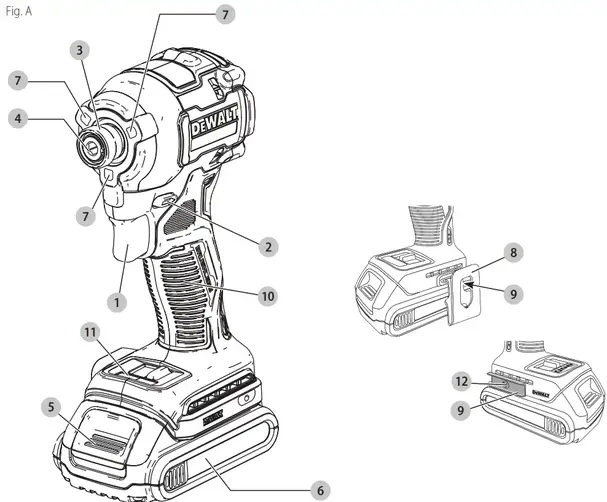
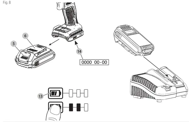 |
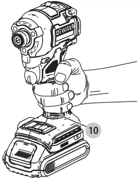 |
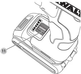 |
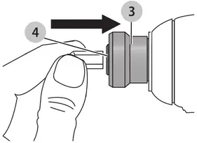 |
BRUSHLESS CORDLESS COMPACT IMPACT DRIVER
DCF850
Congratulations!
You have chosen a DEWALT tool. Years of experience, thorough product development and innovation make DEWALT one of the most reliable partners for professional power tool users.
Technical Data
| DCF850 | ||
| Voltage | VD, | 18 |
| Type | 1/10/20 | |
| Battery type | Li-Ion | |
| Power output | W | 475 |
| No load speed | rpm | |
| Mode 1 | 0-1000 | |
| Mode 2 | 0-2800 | |
| Mode 3 | 0-3250 | |
| Impact rate | ipm | 0-3800 |
| Max torque | Nm | 206. |
| Tool holder | mm | 6. |
| Weight (without battery pack) | kg | 0.95 |
| Noise values and vibration values (triax vector sum) according to EN62841-2-2: | ||
| 14„ (emission sound pressure level) | dB(A) | 88 |
| LwA (sound power level) | dB(A) | 99 |
| K (uncertainty for the given sound level) | dB(A) | 3 |
| Vibration emission value ah = Uncertainty K = | m/s2 m/s2 |
18.5 1.7 |
The vibration and/or noise emission level given in this information sheet has been measured in accordance with a standardized test given in EN62841 and may be used to compare one tool with another. It may be used for a preliminary assessment of exposure.
![]() WARNING: The declared vibration and/or noise emission level represents the impact tightening of fasteners of the maximum capacity of the tool. However, if the tool is used for different applications, with different accessories, or poorly maintained, the vibration and/or noise emission may differ. This may significantly increase the exposure level over the total working period.
WARNING: The declared vibration and/or noise emission level represents the impact tightening of fasteners of the maximum capacity of the tool. However, if the tool is used for different applications, with different accessories, or poorly maintained, the vibration and/or noise emission may differ. This may significantly increase the exposure level over the total working period.
An estimation of the level of exposure to vibration and/ or noise should also take into account the times when the tool is switched off or when it is running but not actually doing the job. This may significantly reduce the exposure level over the total working period.
Identify additional safety measures to protect the operator from the effects of vibration and/or noise such as: maintaining the tool and the accessories, keeping the hands warm (relevant for vibration), and organization of work patterns.
EC-Declaration of Conformity
Machinery Directive
![]() Brushless Cordless Compact Impact Driver DCF850
Brushless Cordless Compact Impact Driver DCF850
DeWALT declares that these products described under
Technical Data are in compliance with:
2006/42/EC, EN62841-1:2015, EN62841-2-2:2014.
These products also comply with Directive 2014/30/EU and
2011/65/EU. For more information, please contact DeWALT at the following address or refer to the back of the manual.
The undersigned is responsible for the compilation of the technical file and makes this declaration on behalf of DeWALT.

Markus Rompel
Vice President of Engineering, PTE-Europe
DEWALT, Richard-Klinger-Straße 11,
65510, Idstein, Germany
07.04.2021
DECLARATION OF CONFORMITY
THE SUPPLY OF MACHINERY (SAFETY)
 REGULATIONS 2008
Brushless Cordless Compact Impact Driver DCF850
DEWALT declares that these products described under “technical data” are in compliance with: EN62841-1:2015, EN62841-2-2:2014
These products conform to the following UK Regulations
The Supply of Machinery (Safety) Regulations, 2008, S.I. 2008/1597 (as amended). Electromagnetic Compatibility Regulations, 2016, S.I.2016/1091 (as amended).
The Restriction of the Use of Certain Hazardous Substances in Electrical and Electronic Equipment Regulations 2012, S.I. 2012/3032 (as amended).
For more information, please contact DEWALT at the following address or refer to the back of the manual.
| Batteries | Chargers/Charge Times (Minutes)*** | ||||||||||||
| Cat # Vc, Ah Weight (kg) | DCB104 DCB107 DCB112 DCB113 DCB115 DCB116 DCB117 DCB118 DCB132 DCB119 | ||||||||||||
| DCB546 | 18/54 | 6.0/2.0 | 1. | 60 | 270 | 170 | 140 | 90 | 80 | 40 | 60 | 90 | X |
| DCB547 | 18/54 | 9.0/3.0 | 1. | 75* | 420 | 210220 | 135* | 110* | 60 | 75* | 135* | X | |
| DCB548 | 18/54 | 12.0/4.0 | 1. | 120 | 540 | 350 | 300 | 180 | 150 | 80 | 120 | 180 | X |
| DCB549 | 18/54 | 15.0/5.0 | 2. | 125 | 730 | 450380230 | 170 | 90 | 125 | 230 X | |||
| DCB181 | 18 | 2. | 35 | 22 | 70 | 453522 | 22 | 22 | 22 | 2245 | |||
| DCB182 | 18 | 4.0 | 0.61 | 60/40** | 185 | 120 | 100 | 60 | 60/45** | 60140** | 60140** | 60120 | |
| DCB183/B/6 | 18 | 2.0 | 0.40 | 30 | 90 | 6050 | 30 | 30 | 30 | 30 | 30 | 60 | |
| DCB184/B/6 | 18 | 5.0 | 0.62 | 75/50** | 240 | 150 | 120 | 75 | 75/60** | 75/50** | 75/50** | 75 | 150 |
| DCB185 | 18 | 1. | 35 | 22 | 60 | 403022 | 22 | 22 | 22 | 2240 | |||
| DCB187 | 18 | 3.0 | 0.54 | 45 | 140 | 907045 | 45 | 45 | 45 | 4590 | |||
| DCB189 | 18 | 4.0 | 0.54 | 60 | 185 | 120 | 100 | 60 | 60 | 60 | 60 | 60120 | |
| DCBP034 | 18 | 2. | 0.32 | 27 | 82 | 504027 | 27 | 27 | 27 | 2750 | |||
*Date code 201811475B or later
**Date code 201536 or later
***Battery charge times matrix provided for guidance only; charge times will vary depending on temperature and condition of batteries.
The undersigned is responsible for the compilation of the technical file and makes this declaration on behalf of DEWALT.

Karl Evans
Vice President Professional Power Tools EANZ GTS
270 Bath Road, Slough
SL1 4DX
England
07.04.2021
![]() WARNING: To reduce the risk of injury, read the instruction manual.
WARNING: To reduce the risk of injury, read the instruction manual.
Definitions: Safety Guidelines
The definitions below describe the level of severity for each signal word. Please read the manual and pay attention to these symbols.
![]() DANGER: Indicates an imminently hazardous situation that, if not avoided, will result in death or serious injury.
DANGER: Indicates an imminently hazardous situation that, if not avoided, will result in death or serious injury.
![]() WARNING: Indicates a potentially hazardous situation that, if not avoided, could result in death or serious injury.
WARNING: Indicates a potentially hazardous situation that, if not avoided, could result in death or serious injury.
![]() CAUTION: Indicates a potentially hazardous situation that, if not avoided, may result in minor or moderate injury.
CAUTION: Indicates a potentially hazardous situation that, if not avoided, may result in minor or moderate injury.
NOTICE: Indicates a practice not related to personal injury that, if not avoided, may result in property damage.
![]() Denotes risk of electric shock.
Denotes risk of electric shock.
![]() Denotes risk of fire.
Denotes risk of fire.
GENERAL POWER TOOL SAFETY WARNINGS
![]() WARNING: Read all safety warnings, instructions, illustrations and specifications provided with this power tool. Failure to follow all instructions listed below may result in electric shock, fire and/or serious injury.
WARNING: Read all safety warnings, instructions, illustrations and specifications provided with this power tool. Failure to follow all instructions listed below may result in electric shock, fire and/or serious injury.
SAVE ALL WARNINGS AND INSTRUCTIONS FOR FUTURE REFERENCE.
The term “power tool” in the warnings refers to your mainsoperated (corded) power tool or battery-operated (cordless) power tool.
- Work Area Safety
a ) Keep work area clean and well lit. Cluttered or dark areas invite accidents.
b ) Do not operate power tools in explosive atmospheres, such as in the presence of flammable liquids, gases or dust. Power tools create sparks which may ignite the dust or fumes.
c ) Keep children and bystanders away while operating a power tool. Distractions can cause you to lose control. - Electrical Safety
a ) Power tool plugs must match the outlet. Never modify the plug in any way. Do not use any adapter plugs with earthed (grounded) power tools. Unmodified plugs and matching outlets will reduce risk of electric shock.
b ) Avoid body contact with earthed or grounded surfaces such as pipes, radiators, ranges and refrigerators. There is an increased risk of electric shock if your body is earthed or grounded.
c ) Do not expose power tools to rain or wet conditions. Water entering a power tool will increase the risk of electric shock.
d ) Do not abuse the cord. Never use the cord for carrying, pulling or unplugging the power tool. Keep cord away from heat, oil, sharp edges or moving parts. Damaged or entangled cords increase the risk of electric shock.
e ) When operating a power tool outdoors, use an extension cord suitable for outdoor use. Use of a cord suitable for outdoor use reduces the risk of electric shock.
f ) If operating a power tool in a damp location is unavoidable, use a residual current device (RCD) protected supply. Use of an RCD reduces the risk of electric shock. - Personal Safety
a ) Stay alert, watch what you are doing and use common sense when operating a power tool. Do not use a power tool while you are tired or under the influence of drugs, alcohol or medication. A moment of inattention while operating power tools may result in serious personal injury.
b ) Use personal protective equipment. Always wear eye protection. Protective equipment such as a dust mask, non-skid safety shoes, hard hat or hearing protection used for appropriate conditions will reduce personal injuries.
c ) Prevent unintentional starting. Ensure the switch is in the off-position before connecting to power source and/or battery pack, picking up or carrying the tool. Carrying power tools with your finger on the switch or energising power tools that have the switch on invites accidents.
d ) Remove any adjusting key or wrench before turning the power tool on. A wrench or a key left attached to a rotating part of the power tool may result in personal injury.
e ) Do not overreach. Keep proper footing and balance at all times. This enables better control of the power tool in unexpected situations.
f ) Dress properly. Do not wear loose clothing or jewellery. Keep your hair and clothing away from moving parts. Loose clothes, jewellery or long hair can be caught in moving parts.
g ) If devices are provided for the connection of dust extraction and collection facilities, ensure these are connected and properly used. Use of dust collection can reduce dust-related hazards.
h ) Do not let familiarity gained from frequent use of tools allow you to become complacent and ignore tool safety principles. A careless action can cause severe injury within a fraction of a second. - Power Tool Use and Care
a ) Do not force the power tool. Use the correct power tool for your application. The correct power tool will do the job better and safer at the rate for which it was designed.
b ) Do not use the power tool if the switch does not turn it on and off. Any power tool that cannot be controlled with the switch is dangerous and must be repaired.
c ) Disconnect the plug from the power source and/ or remove the battery pack, if detachable, from the power tool before making any adjustments, changing accessories, or storing power tools. Such preventive safety measures reduce the risk of starting the power tool accidentally.
d ) Store idle power tools out of the reach of children and do not allow persons unfamiliar with the power tool or these instructions to operate the power tool. Power tools are dangerous in the hands of untrained users.
e ) Maintain power tools and accessories. Check for misalignment or binding of moving parts, breakage of parts and any other condition that may affect the power tool’s operation. If damaged, have the power tool repaired before use. Many accidents are caused by poorly maintained power tools.
f ) Keep cutting tools sharp and clean. Properly maintained cutting tools with sharp cutting edges are less likely to bind and are easier to control.
g ) Use the power tool, accessories and tool bits, etc. in accordance with these instructions, taking into account the working conditions and the work to be performed. Use of the power tool for operations different from those intended could result in a hazardous situation.
h ) Keep handles and grasping surfaces dry, clean and free from oil and grease. Slippery handles and grasping surfaces do not allow for safe handling and control of the tool in unexpected situations. - Battery Tool Use and Care
a ) Recharge only with the charger specified by the manufacturer. A charger that is suitable for one type of battery pack may create a risk of fire when used with another battery pack.
b ) Use power tools only with specifically designated battery packs. Use of any other battery packs may create a risk of injury and fire.
c ) When the battery pack is not in use, keep it away from other metal objects, like paper clips, coins, keys, nails, screws or other small metal objects, that can make a connection from one terminal to another. Shorting the battery terminals together may cause burns or a fire.
d ) Under abusive conditions, liquid may be ejected from the battery; avoid contact. If contact accidentally occurs, flush with water. If liquid contacts eyes, additionally seek medical help. Liquid ejected from the battery may cause irritation or burns.
e ) Do not use a battery pack or tool that is damaged or modified. Damaged or modified batteries may exhibit unpredictable behaviour resulting in fire, explosion or risk of injury.
f ) Do not expose a battery pack or tool to fire or excessive temperature. Exposure to fire or temperature above 130 °C may cause explosion.
g ) Follow all charging instructions and do not charge the battery pack or tool outside the temperature range specified in the instructions. Charging improperly or at temperatures outside the specified range may damage the battery and increase the risk of fire. - Service
a ) Have your power tool serviced by a qualified repair person using only identical replacement parts. This will ensure that the safety of the power tool is maintained. b ) Never service damaged battery packs. Service of battery packs should only be performed by the manufacturer or authorized service providers..
Additional Specific Safety Rules for Impact Wrenches/Drivers
· Hold power tool by insulated gripping surfaces when performing an operation where the fastener may contact hidden wiring. Fasteners contacting a “live” wire may make exposed metal parts of the power tool “live” and could give the operator an electric shock.
Residual Risks
In spite of the application of the relevant safety regulations and the implementation of safety devices, certain residual risks cannot be avoided. These are Impairments to hearing.
- Risk of personal injury due to flying particles.
- Risk of burns due to accessories becoming hot during operation.
- Risk of personal injury due to prolonged use.
SAVE THESE INSTRUCTIONS
Chargers
DEWALT chargers require no adjustment and are designed to be as easy as possible to operate.
Electrical Safety
The electric motor has been designed for one voltage only. Always check that the battery pack voltage corresponds to the voltage on the rating plate. Also, make sure that the voltage of your charger corresponds to that of your mains.
 Your DEWALT charger is double insulated in accordance with EN60335; therefore no earth wire is required. If the supply cord is damaged, it must be replaced by a specially prepared cord available through the DEWALT service organization.
Mains Plug Replacement (U.K. & Ireland Only)
If a new mains plug needs to be fitted:
- Safely dispose of the old plug.
- Connect the brown lead to the live terminal in the plug.
- Connect the blue lead to the neutral terminal.
![]() WARNING: No connection is to be made to the earth terminal. Follow the fitting instructions supplied with good quality plugs. Recommended fuse: 3 A.
WARNING: No connection is to be made to the earth terminal. Follow the fitting instructions supplied with good quality plugs. Recommended fuse: 3 A.
Using an Extension Cable
An extension cord should not be used unless absolutely necessary. Use an approved extension cable suitable for the power input of your charger (see Technical Data). The minimum conductor size is 1 mm2; the maximum length is 30 m.
When using a cable reel, always unwind the cable completely.
Important Safety Instructions for All Battery Chargers
SAVE THESE INSTRUCTIONS: This manual contains important safety and operating instructions for compatible battery chargers (refer to Technical Data).
- Before using the charger, read all instructions and cautionary markings on the charger, battery pack, and product using the battery pack.
![]() WARNING: Shock hazard. Do not allow any liquid to get inside the charger. Electric shock may result.
WARNING: Shock hazard. Do not allow any liquid to get inside the charger. Electric shock may result.
![]() WARNING: We recommend the use of a residual current device with a residual current rating of 30mA or less.
WARNING: We recommend the use of a residual current device with a residual current rating of 30mA or less.
![]() CAUTION: Burn hazard. To reduce the risk of injury, charge only DEWALT rechargeable batteries. Other types of batteries may burst to cause personal injury and damage.
CAUTION: Burn hazard. To reduce the risk of injury, charge only DEWALT rechargeable batteries. Other types of batteries may burst to cause personal injury and damage.
![]() CAUTION: Children should be supervised to ensure that they do not play with the appliance.
CAUTION: Children should be supervised to ensure that they do not play with the appliance.
NOTICE: Under certain conditions, with the charger plugged into the power supply, the exposed charging contacts inside the charger can be shorted by foreign material. Foreign materials of a conductive nature such as, but not limited to, steel wool, aluminum foil or any buildup of metallic particles should be kept away from charger cavities. Always unplug the charger from the power supply when there is no battery pack in the cavity. Unplug charger before attempting to clean
- DO NOT attempt to charge the battery pack with any chargers other than the ones in this manual. The charger and battery pack are specifically designed to work together.
- These chargers are not intended for any uses other than charging DEWALT rechargeable batteries. Any other uses may result in a risk of fire, electric shock or electrocution.
- Do not expose the charger to rain or snow.
- Pull by plug rather than cord when disconnecting charger. This will reduce the risk of damage to the electric plug and cord.
- Make sure that the cord is located so that it will not be stepped on, tripped over, or otherwise subjected to damage or stress.
- Do not use an extension cord unless it is absolutely necessary. Use of improper extension cord could result in a risk of fire, electric shock, or electrocution.
- Do not place any object on top of the charger or place the charger on a soft surface that might block the ventilation slots and result in excessive internal heat. Place the charger in a position away from any heat source. The charger is ventilated through slots in the top and the bottom of the housing.
- Do not operate chargers with damaged cords or plugs– have them replaced immediately.
- Do not operate the charger if it has received a sharp blow, been dropped, or otherwise damaged in any way. Take it to an authorized service center.
- Do not disassemble the charger; take it to an authorized service center when service or repair is required. Incorrect reassembly may result in a risk of electric shock, electrocution or fire.
- In case of a damaged power supply cord, the supply cord must be replaced immediately by the manufacturer, its service agent or similarly qualified person to prevent any hazard
- Disconnect the charger from the outlet before attempting any cleaning. This will reduce the risk of electric shock. Removing the battery pack will not reduce this risk. · NEVER attempt to connect two chargers together.
- The charger is designed to operate on standard 230V household electrical power. Do not attempt to use it on any other voltage. This does not apply to the vehicular charger.
Charging a Battery (Fig. B)
- Plug the charger into an appropriate outlet before inserting the battery pack.
- Insert the battery pack 6 into the charger, making sure the battery pack is fully seated in the charger. The red (charging) light will blink repeatedly indicating that the charging process has started.
- The completion of the charge will be indicated by the red light remaining ON continuously. The battery pack is fully charged and may be used at this time or left in the charger. To remove the battery pack from the charger, push the battery release button 5 on the battery pack.
NOTE: To ensure maximum performance and life of lithium-ion battery packs, charge the battery pack fully before first use.
Charger Operation
Refer to the indicators below for the charge status of the battery pack.
Charge Indicators
*The red light will continue to blink, but a yellow indicator light will be illuminated during this operation. Once the battery pack has reached an appropriate temperature, the yellow light will turn off and the charger will resume the charging procedure. The compatible charger(s) will not charge a faulty battery pack. The charger will indicate faulty battery by refusing to light.
NOTE: This could also mean a problem with a charger.
If the charger indicates a problem, take the charger and battery pack to be tested at an authorized service centre.
Hot/Cold Pack Delay
When the charger detects a battery pack that is too hot or too cold, it automatically starts a Hot/Cold Pack Delay, suspending charging until the battery pack has reached an appropriate temperature. The charger then automatically switches to the pack charging mode. This feature ensures maximum battery pack life.
A cold battery pack will charge at a slower rate than a warm battery pack. The battery pack will charge at that slower rate throughout the entire charging cycle and will not return to the maximum charge rate even if the battery pack warms.
The DCB118 charger is equipped with an internal fan designed to cool the battery pack. The fan will turn on automatically when the battery pack needs to be cooled. Never operate the charger if the fan does not operate properly or if ventilation slots are blocked. Do not permit foreign objects to enter the interior of the charger.
Electronic Protection system
XR Li-Ion tools are designed with an Electronic Protection System that will protect the battery pack against overloading, overheating or deep discharge.
The tool will automatically turn off if the Electronic Protection System engages. If this occurs, place the lithium-ion battery pack on the charger until it is fully charged.
Wall Mounting
These chargers are designed to be wall mountable or to sit upright on a table or work surface. If wall mounting, locate the charger within reach of an electrical outlet, and away from a corner or other obstructions which may impede air flow. Use the back of the charger as a template for the location of the mounting screws on the wall. Mount the charger securely using drywall screws (purchased separately) at least 25.4 mm long with a screw head diameter of 79 mm, screwed into wood to an optimal depth leaving approximately 5.5 mm of the screw exposed. Align the slots on the back of the charger with the exposed screws and fully engage them in the slots.
Charger Cleaning Instructions
![]() WARNING: Shock hazard. Disconnect the charger from the AC outlet before cleaning. Dirt and grease may be removed from the exterior of the charger using a cloth or soft non-metallic brush. Do not use water or any cleaning solutions. Never let any liquid get inside the tool; never immerse any part of the tool into a liquid.
WARNING: Shock hazard. Disconnect the charger from the AC outlet before cleaning. Dirt and grease may be removed from the exterior of the charger using a cloth or soft non-metallic brush. Do not use water or any cleaning solutions. Never let any liquid get inside the tool; never immerse any part of the tool into a liquid.
Battery Packs
Important Safe Instructions for All Battery Packs
When ordering replacement battery packs, be sure to include the catalog number and voltage.
The battery pack is not fully charged out of the carton. Before using the battery pack and charger, read the safety instructions below. Then follow the charging procedures outlined.
READ ALL INSTRUCTIONS
- Do not charge or use batteries in explosive atmospheres, such as in the presence of flammable liquids, gases or dust. Inserting or removing the battery from the charger may ignite the dust or fumes.
- Never force battery pack into charger. Do not modify the battery pack in any way to fit into a non-compatible charger as the battery pack may rupture causing serious personal injury.
- Charge the battery packs only in DEWALT chargers.
- DO NOT splash or immerse in water or other liquids.
- Do not store or use the tool and battery pack in locations where the temperature may reach or exceed 40 °C (104 °F) (such as outside sheds or metal buildings in summer).
- Do not incinerate the battery pack even if it is severely damaged or is completely worn out. The battery pack can explode in a fire. Toxic fumes and materials are created when lithium-ion battery packs are burned.
- If battery contents come into contact with the skin, immediately wash the area with mild soap and water. If battery liquid gets into the eye, rinse water over the open eye for 15 minutes or until irritation ceases. If medical attention is needed, the battery electrolyte is composed of a mixture of liquid organic carbonates and lithium salts.
- Contents of opened battery cells may cause respiratory irritation. Provide fresh air. If symptoms persist, seek medical attention.
 WARNING: Burn hazard. Battery liquid may be flammable if exposed to spark or flame.
 WARNING: Never attempt to open the battery pack for any reason. If the battery pack case is cracked or damaged, do not insert it into the charger. Do not crush, drop or damage the battery pack. Do not use a battery pack or charger that has received a sharp blow, been dropped, run over or damaged in any way (i.e., pierced with a nail, hit with a hammer, stepped on). Electric shock or electrocution may result. Damaged battery packs should be returned to
a service center for recycling.
WARNING: Fire hazard. Do not store or carry the battery pack so that metal objects can contact exposed battery terminals. For example, do not place the battery pack in aprons, pockets, tool boxes, product kit boxes, drawers, etc., with loose nails, screws, keys, etc.
CAUTION: When not in use, place the tool on its side on a stable surface where it will not cause a tripping or falling hazard. Some tools with large battery packs will stand upright on the battery pack but may be easily knocked over.
Transportation
![]() WARNING: Fire hazard. Transporting batteries can possibly cause a fire if the battery terminals inadvertently come in contact with conductive materials. When transporting batteries, make sure that the battery terminals are protected and well insulated from materials that could contact them and cause a short circuit.
WARNING: Fire hazard. Transporting batteries can possibly cause a fire if the battery terminals inadvertently come in contact with conductive materials. When transporting batteries, make sure that the battery terminals are protected and well insulated from materials that could contact them and cause a short circuit.
DEWALT batteries comply with all applicable shipping regulations as prescribed by industry and legal standards which include UN Recommendations on the Transport of Dangerous Goods; International Air Transport Association (IATA) Dangerous Goods Regulations, International Maritime Dangerous Goods (IMDG) Regulations, and the European Agreement Concerning The International Carriage of Dangerous Goods by Road (ADR). Lithium-ion cells and batteries have been tested to section 38.3 of the UN Recommendations on the Transport of Dangerous Goods Manual of Tests and Criteria.
In most instances, shipping a DEWALT battery pack will be excepted from being classified as a fully regulated Class 9 Hazardous Material. In general, only shipments containing a lithium-ion battery with an energy rating greater than 100 Watt Hours (Wh) will require being shipped as fully regulated Class 9. All lithium-ion batteries have the Watt Hour rating marked on the pack. Furthermore, due to regulation complexities, DEWALT does not recommend air shipping lithium-ion battery packs alone regardless of Watt Hour rating. Shipments of tools with batteries (combo kits) can be air shipped as excepted if the Watt Hour rating of the battery pack is no greater than 100 Whr.
Regardless of whether a shipment is considered excepted or fully regulated, it is the shipper’s responsibility to consult the latest regulations for packaging, labeling/marking and documentation requirements.
The information provided in this section of the manual is provided in good faith and believed to be accurate at the time the document was created. However, no warranty, expressed or implied, is given. It is the buyer’s responsibility to ensure that its activities comply with the applicable regulations.
Transporting the FlEXVOlTTM Battery
The DEWALT FLEXVOLTTM battery has two modes: Use and Transport.
Use Mode: When the FLEXVOLTTM battery stands alone or is in a DEWALT 18V product, it will operate as an 18V battery. When the FLEXVOLTTM battery is in a 54V or a 108V (two 54V batteries) product, it will operate as a 54V battery.
Transport Mode:
When the cap is attached to the FLEXVOLTTM battery, the battery is in Transport mode. Keep the cap for shipping.
When in Transport mode, strings of cells are electrically disconnected within the pack resulting in 3 batteries with a lower Watt-hour (Wh) rating as compared to 1 battery with a higher Watt hour rating. This increased quantity of 3 batteries with the lower Watt hour rating can exempt the pack from certain shipping regulations that are imposed upon the higher Watt hour batteries.
For example, the Transport Example of Use and Transport Label Marking Wh rating might indicate 3 x 36 Wh, meaning 3 batteries of 36 Wh each. The Use Wh rating might indicate 108 Wh (1 battery implied).

- The best storage place is one that is cool and dries away from direct sunlight and excess heat or cold. For optimum battery performance and life, store battery packs in the room the temperature when not in use.
- For long storage, it is recommended to store a fully charged battery pack in a cool, dry place out of the charger for optimal results.
NOTE: Battery packs should not be stored completely depleted of charge. The battery pack will need to be recharged before use.
Labels on Charger and Battery Pack
In addition to the pictographs used in this manual, the labels on the charger and the battery pack may show the following pictographs:
| Read the instruction manual before use. | |
| See Technical Data for charging time. | |
| Do not probe with conductive objects. | |
| Do not charge damaged battery packs. | |
| Do not expose to water. | |
| Have defective cords replaced immediately. | |
| Charge only between 4 ˚C and 40 ˚C. | |
| Only for indoor use. | |
| Discard the battery pack with due care for the environment. | |
| Charge DeWALT battery packs only with designated DeWALT chargers. Charging battery packs other than the designated DeWALT batteries with a DeWALT charger may make them burst or lead to other dangerous situations. | |
| Do not incinerate the battery pack. | |
| USE (without transport cap). Example: Wh rating indicates 108 Wh (1 battery with 108 Wh). | |
| TRANSPORT (with built-in transport cap). Example: Wh rating indicates 3 x 36 Wh (3 batteries of 36 Wh). | |
| Do not incinerate the battery pack. |
Battery Type
The following tools operate on an 18-volt battery pack: DCF850.
These battery packs may be used: DCB181, DCB182, DCB183,
DCB183B, DCB183G, DCB184, DCB184B, DCB184G, DCB185,
DCB187, DCB189, DCBP034, DCB546, DCB547, DCB548, DCB549.
Refer to Technical Data for more information.
Package Contents
- The package contains:
- 1 Impact driver
- 1 Charger
- 1 Li-Ion battery pack (C1, D1, L1, M1, P1, S1, T1, X1, Y1 models)
- 2 Li-Ion battery packs (C2, D2, L2, M2, P2, S2, T2, X2, Y2 models)
- 3 Li-Ion battery packs (C3, D3, L3, M3, P3, S3, T3, X3, Y3 models)
- 1 Magnetic bit holder
- 1 Belt hook
- 1 Kitbox
- 1 Instruction manual
- 1 Tool ConnectTM App instruction manual (B models)
NOTE: Battery packs, chargers, and kit boxes are not included with N-models.
- Check for damage to the tool, parts or accessories which may have occurred during transport.
- Take the time to thoroughly read and understand this manual prior to operation.
Markings on Tool
The following pictograms are shown on the tool:
![]() Read the instruction manual before use.
Read the instruction manual before use.
 Visible radiation. Do not stare into light.
Date Code Position (Fig. B)
The date code 14, which also includes the year of manufacture, is printed into the housing.
Example:
2019 XX XX
Year of Manufacture
Description (Fig. A)
![]() WARNING: Never modify the power tool or any part of it.
WARNING: Never modify the power tool or any part of it.
Damage or personal injury could result.
- Trigger switch
- Forward/reverse control button
- Chuck collar
- 6.35 mm hex chuck
- Battery release button
- Battery pack
- Worklights
- Belt hook (optional accessory)
- Mounting screw
- Main handle
- Mode selector
- Magnetic bit holder
Intended Use
This impact driver is designed for professional impact screwdriving applications. The impact function makes this tool particularly useful for driving fasteners in wood, metal and concrete.
DO NOT use under wet conditions or in the presence of flammable liquids or gases. This impact driver is a professional power tool.
DO NOT let children come into contact with the tool. Supervision is required when inexperienced operators use this tool. · Young children and the infirm. This appliance is not intended for use by young children or infirm persons without supervision. · This product is not intended for use by persons (including children) suffering from diminished physical, sensory or mental abilities; lack of experience, knowledge, or skills unless they are supervised by a person responsible for their safety. Children should never be left alone with this product.
ASSEMBLY AND ADJUSTMENTS
![]() WARNING: To reduce the risk of serious personal injury, turn the tool off and disconnect the battery pack before making any adjustments or removing/ installing attachments or accessories. An accidental start-up can cause injury.
WARNING: To reduce the risk of serious personal injury, turn the tool off and disconnect the battery pack before making any adjustments or removing/ installing attachments or accessories. An accidental start-up can cause injury.
![]() WARNING: Use only DEWALT battery packs and chargers.
WARNING: Use only DEWALT battery packs and chargers.
Inserting and Removing the Battery Pack from the Tool (Fig. B)
NOTE: Make sure your battery pack 6 is fully charged.
To Install the Battery Pack into the Tool Handle
- Align the battery pack 6 with the rails inside the tool’s handle (Fig. B).
- Slide it into the handle until the battery pack is firmly seated in the tool and ensure that you hear the lock snap into place.
To Remove the Battery Pack from the Tool - Press the release button 5 and firmly pull the battery pack out of the tool handle.
- Insert the battery pack into the charger as described in the charger section of this manual.
Fuel Gauge Battery Packs (Fig. B) Some DEWALT battery packs include a fuel gauge which consists of three green LED lights that indicate the level of charge remaining in the battery pack. To actuate the fuel gauge, press and hold the fuel gauge button 13. A combination of the three green LED lights will illuminate designating the level of charge left. When the level of charge in the battery is below the usable limit, the fuel gauge will not illuminate and the battery will need to be recharged
NOTE: The fuel gauge is only an indication of the charge left on the battery pack. It does not indicate tool functionality and is subject to variation based on product components, temperature and end-user application.
Belt Hook and Magnetic Bit Holder (Fig. A)
![]() WARNING: To reduce the risk of serious personal injury, turn tool off and disconnect battery pack before making any adjustments or removing/
WARNING: To reduce the risk of serious personal injury, turn tool off and disconnect battery pack before making any adjustments or removing/
installing attachments or accessories.
![]() WARNING: To reduce the risk of serious personal injury, DO NOT suspend tool overhead or suspend objects from the belt hook. ONLY hang tool’s belt hook from a work belt.
WARNING: To reduce the risk of serious personal injury, DO NOT suspend tool overhead or suspend objects from the belt hook. ONLY hang tool’s belt hook from a work belt.
![]() WARNING: To reduce the risk of serious personal injury, ensure the screw holding the belt hook is secure.
WARNING: To reduce the risk of serious personal injury, ensure the screw holding the belt hook is secure.
IMPORTANT: When attaching or replacing the belt hook or magnetic bit holder, use only the screw 9 that is provided. Be sure to securely tighten the screw. The belt hook 8 and magnetic bit holder 12 can be attached to either side of the tool using only the screw 9 provided, to accommodate left- or right-handed users. If the hook or magnetic bit holder is not desired at all, it can be removed from the tool. To move the belt hook or magnetic bit holder, remove the screw 9 that holds it in place then reassemble on the opposite side. Be sure to securely tighten the screw.
OPERATION
Instructions for Use
![]() WARNING: Always observe the safety instructions and applicable regulations.
WARNING: Always observe the safety instructions and applicable regulations.
![]() WARNING: To reduce the risk of serious personal injury, turn the tool off and disconnect the battery pack before making any adjustments or removing/ installing attachments or accessories. An accidental start-up can cause injury.
WARNING: To reduce the risk of serious personal injury, turn the tool off and disconnect the battery pack before making any adjustments or removing/ installing attachments or accessories. An accidental start-up can cause injury.
Proper Hand Position (Fig. A, C)
![]() WARNING: To reduce the risk of serious personal injury, ALWAYS use proper hand position as shown.
WARNING: To reduce the risk of serious personal injury, ALWAYS use proper hand position as shown.
![]() WARNING: To reduce the risk of serious personal injury, ALWAYS hold securely in anticipation of a sudden reaction.
WARNING: To reduce the risk of serious personal injury, ALWAYS hold securely in anticipation of a sudden reaction.
Proper hand position requires one hand on the main handle 10 .
Variable Speed Trigger Switch (Fig. A)
To turn the tool on, squeeze the trigger switch 1 . To turn the tool off, release the trigger switch. Your tool is equipped with a brake. The tool will stop when the trigger switch is fully released.
The variable speed switch enables you to start the application at a slow speed. The further you squeeze the trigger, the faster the tool will operate. For maximum tool life, use variable speed only for starting holes or fasteners.
NOTE: Continuous use in variable speed range is not recommended. It may damage the switch and should be avoided.
Forward/Reverse Control Button (Fig. A)
A forward/reverse control button 2 determines the direction of the tool and also serves as a lock-off button. To select forward rotation, release the trigger switch 1 and depress the forward/reverse control button 2 on the right side of the tool.
To select reverse, release trigger switch 1 and depress the forward/reverse control button 2 on the left side of the tool. The center position of the control button locks the trigger switch in the off position. When changing the position of the control button, be sure the trigger is released.
NOTE: The first time the tool is run after changing the direction of rotation, you may hear a click on startup. This is normal and does not indicate a problem.
Worklights (Fig. A)
There are three worklights 7 located around the 6.35 mm hex chuck 4. The worklights are activated when the trigger switch is depressed.
When the trigger is released, the work light will stay illuminated for up to 20 seconds.
NOTE: The worklights are for lighting the immediate work surface and are not intended to be used as a flashlight.
Mode Selector (Fig. A, D)
Your tool is equipped with a mode selector 11 which allows you to select one of three modes. Select the mode based on the application and control the speed of the tool using the variable speed trigger switch 1 .
Precision Drive (Fig. D)
In addition to normal impacting modes, this tool features the Precision Drive mode which enables greater control in lighter applications to avoid damage to materials or fasteners. It is ideal for light applications such as cabinet hinge screws or machine screws. Precision Drive mode will work as a screwdriver in light applications, before hesitating as the screw head reaches the workpiece, and then (if required) start a slow controlled impact to ensure the head ends perfectly flush.
NOTE: This mode is for light-duty screwdriving applications. If the tool will not drive a fastener in Precision Mode, please select mode 2 which will give the additional power required.
| DCF850 | |||
| Mode 1 | Precision Drive | rpm | 0–1000 |
| Mode 2 | Normal Impacting | rpm | 0–2800 |
| Mode 3 | High-Speed Impacting | rpm | 0–3250 |
Quick-Release Chuck (Fig. A, E, F)
![]() WARNING: Use only impact accessories. Non-impact accessories may break and cause a hazardous condition. Inspect accessory prior to use to ensure that it contains no cracks
WARNING: Use only impact accessories. Non-impact accessories may break and cause a hazardous condition. Inspect accessory prior to use to ensure that it contains no cracks
NOTE: The chuck accepts 6.35 mm hex accessories only. Place the forward/reverse button 2 in the lock-off (center) position or remove battery pack before changing accessories.
To install an accessory, fully insert the accessory. The accessory is locked into place (Fig. E). To remove an accessory, pull the chuck collar 3 away from the front of the tool. Remove the accessory (Fig. F).
Usage
Your impact tool generates the following maximum torque:
Cat #………………………….nm
DCF850………………………… 206.2
![]() CAUTION: Ensure the fastener and/or system will withstand the level of torque generated by the tool. Excessive torque may cause breakage and possible personal injury.
CAUTION: Ensure the fastener and/or system will withstand the level of torque generated by the tool. Excessive torque may cause breakage and possible personal injury.
- Place the accessory into the chuck. Keep the tool pointed straight at the workpiece.
- Press switch to start operation. Release the switch to stop operation. Always check torque with a torque wrench, as the fastening torque is affected by many factors including the following:
– Voltage: Low voltage, due to a nearly discharged battery, will reduce fastening torque.
– Socket size: Failure to use the correct socket size will cause a reduction in fastening torque.
– Bolt Size: Larger bolt diameters generally require higher fastening torque. Fastening torque will also vary according to length, grade, and torque coefficient.
– Bolt: Ensure that all threads are free of rust and other debris to allow proper fastening torque.
– Material: The type of material and surface finish of the material will affect fastening torque.
– Fastening Time: Longer fastening time results in increased fastening torque. Using a longer fastening time than recommended could cause the fasteners to be overstressed, stripped or damaged.
MAINTENANCE
Your DEWALT power tool has been designed to operate over a long period of time with a minimum of maintenance. Continuous satisfactory operation depends upon proper tool care and regular cleaning.
![]() WARNING: To reduce the risk of serious personal injury, turn tool off and disconnect battery pack before making any adjustments or removing/ installing attachments or accessories. An accidental start-up can cause injury.
WARNING: To reduce the risk of serious personal injury, turn tool off and disconnect battery pack before making any adjustments or removing/ installing attachments or accessories. An accidental start-up can cause injury.
The charger and battery pack are not serviceable.
Lubrication
![]() Your power tool requires no additional lubrication.
Your power tool requires no additional lubrication.
Cleaning
![]() WARNING: Blow dirt and dust out of the main housing with dry air as often as dirt is seen collecting in and around the air vents. Wear approved eye protection and approved dust masks when performing this procedure.
WARNING: Blow dirt and dust out of the main housing with dry air as often as dirt is seen collecting in and around the air vents. Wear approved eye protection and approved dust masks when performing this procedure.
![]() WARNING: Never use solvents or other harsh chemicals for cleaning the non-metallic parts of the tool. These chemicals may weaken the materials used in these parts. Use a cloth dampened only with water and mild soap. Never let any liquid get inside the tool; never immerse any part of the tool into a liquid.
WARNING: Never use solvents or other harsh chemicals for cleaning the non-metallic parts of the tool. These chemicals may weaken the materials used in these parts. Use a cloth dampened only with water and mild soap. Never let any liquid get inside the tool; never immerse any part of the tool into a liquid.
Optional Accessories
![]() WARNING: Since accessories, other than those offered by DEWALT, have not been tested with this product, use of such accessories with this tool could be hazardous. To reduce the risk of injury, only DEWALT recommended accessories should be used with this product.
WARNING: Since accessories, other than those offered by DEWALT, have not been tested with this product, use of such accessories with this tool could be hazardous. To reduce the risk of injury, only DEWALT recommended accessories should be used with this product.
![]() WARNING: Use only impact accessories. Non-impact accessories may break and cause a hazardous condition. Inspect accessories prior to use to ensure that they contain no cracks. Consult your dealer for further information on the appropriate accessories.
WARNING: Use only impact accessories. Non-impact accessories may break and cause a hazardous condition. Inspect accessories prior to use to ensure that they contain no cracks. Consult your dealer for further information on the appropriate accessories.
Protecting the Environment
![]() Separate collection. Products and batteries marked with this symbol must not be disposed of with normal household waste. Products and batteries contain materials that can be recovered or recycled reducing the demand for raw materials. Please recycle electrical products and batteries according to local provisions. Further information is available at www.2helpU.com.
Separate collection. Products and batteries marked with this symbol must not be disposed of with normal household waste. Products and batteries contain materials that can be recovered or recycled reducing the demand for raw materials. Please recycle electrical products and batteries according to local provisions. Further information is available at www.2helpU.com.
Rechargeable Battery Pack
This long-life battery pack must be recharged when it fails to produce sufficient power on jobs that were easily done before. At the end of its technical life, discard it with due care for our environment:
- Run the battery pack down completely, then remove it from the tool.
- Li-Ion cells are recyclable. Take them to your dealer or a local recycling station. The collected battery packs will be recycled or disposed of properly.
United Kingdom
DeWALT, 270 Bath Road;
Slough, Berks SL1 4DX
Tel:01753-567055
Fax: 01753-572112
www.dewalt.co.uk
[email protected]
DEWALT DXAEPI1000 1000W Power Inverter Car Converter
DEWALT DXAEPI1000 1000W Power Inverter Car Converter
 WARNING: Read all instructions before operating product.
Failure to follow all instructions listed below may result in electric shock, fire and/or serious injury.
This product or its power cord contains lead, a chemical known to the State of California to cause cancer and birth defect or other reproductive harm. Wash hands after handling. For more information go to www.P65Warnings.ca.gov.
Definitions: Safety Guidelines
The definitions below describe the level of severity for each signal word. Please read the manual and pay attention to these symbols.
DANGER: Indicates an imminently hazardous situation which, if not avoided, will result in death or serious injury.
WARNING: Indicates a potentially hazardous situation which, if not avoided, could result in death or serious injury.
CAUTION: Indicates a potentially hazardous situation which, if not avoided, may result in minor or moderate injury.
NOTICE: Indicates a practice not related to personal injury which, if not avoided, may result in property damage.
IF YOU HAVE ANY QUESTIONS OR COMMENTS ABOUT THIS WALT TOOL, CALL US TOLL FREE AT: 1-888-394-3392.
1000 Watt Power Inverter
The DXAEPI1000 1000 Watt Power Inverter is a DeWALT 1000W power inverter configured to supply continuous power in the form of two 120 volt AC outlets and three 5 volt USB power ports to run most
household or electronic appliances.
Important Safety Instructions
- Keep these instructions.
- Heed all warnings.
- Follow all instructions.
- Avoid dangerous environments. Don’t use the inverter in damp or wet locations. Don’t use the inverter in the rain or snow.
- Clean only with a dry cloth.
- Keep the inverter away from children. This is not a toy!
- Store indoors. When not in use, inverters should be stored indoors in dry, and high or locked-up places – out of the reach of children.
- Always turn the inverter off by pressing the on/off button, then disconnecting it from the DC source when not in use.
- Only use attachments/accessories specified by the manufacturer.
- Check for damaged parts. Any part that is damaged should be properly repaired or replaced by manufacturer, unless otherwise indicated elsewhere in this instruction manual before further use.
Servicing is required when the apparatus has been damaged in any way, such as power-supply cord or plug is damaged, liquid has been spilled or objects have fallen into the apparatus, the apparatus has been exposed to rain or moisture, does not operate normally, or has been dropped. Contact the manufacturer at 1-888-394-3392 for more information. - Apparatus shall not be exposed to dripping or splashing and no
objects filled with liquids shall be placed on the apparatus. - Un refroidissement approprié est essentiel lors de l’utilisation de l’onduleur. Ne placez pas l’appareil près de la bouche d’aération véhicule ou en plein soleil.
READ ALL INSTRUCTIONS
Specific Safety Instructions for Inverters WARNING – To reduce the risk of electric shock:
- Do not connect to AC distribution wiring.
- Do not make any electrical connections or disconnections in areas designated as IGNITION PROTECTED. This includes DC cigarette lighter type plug connection. This unit is NOT approved for ignition protected areas.
- NEVER immerse the unit in water or any other liquid, or use when wet.
- Do not insert foreign objects into the inverter’s outlets.
- Do not attach USB hubs or more than one personal electronic device to each USB Port.
- Extension cords. Make sure your extension cord is in good condition. When using an extension cord, be sure to use one heavy enough to carry the current your product will draw. An undersized cord will cause a drop in line voltage resulting in loss of power and overheating.
The following table shows the correct size to use depending on cord length and nameplate ampere rating. If in doubt, use the next heavier gauge. The smaller the gauge number, the heavier the cord.
MINIMUM GAGE FOR CORD SETS
Volts Total Length of Cord in Feet 120V 0-25 26-50 51-100 101-150 (0-7.6m) (7.6-15.2m) (15.2-30.4m) (30.4-45.7m) 240V 0-50 51-100 101-200 201-300
(0-15.2m) (15.2-30.4m) (30.4-60.9m) (60.9-91.4m) Ampere Rating Extension Cord Length
More Not more 0’-25’ 26’-50’ 51 ’-100 ’ 101’ -150 ’
Than Than American Wire Gage (AWG)
0 – 6 18 16 16 14 6 – 10 18 16 14 12 10 – 12 16 16 14 12 12 – 16 14 12 Not Recommended
Outdoor use extension cords.
When an appliance plugged into this unit is used outdoors, use only extension cords intended for use outdoors and so marked. Note that this inverter is not intended to be used outdoors.
WARNING – To reduce the risk of fire:
- Do not operate near flammable materials, fumes or gases.
- Do not expose to extreme heat or flames.
CAUTION – To reduce the risk of injury or property damage: - When using this unit in a vehicle, check the vehicle owner’s manual for maximum power rating and recommended output. Do not install in engine compartment — install in a well ventilated area.
- Disconnect appliance plug from inverter outlet before working on the appliance.
- Do not attempt to connect or set up the inverter or its components while operating your vehicle. Not paying attention to the road may result in a serious accident.
- Always use the inverter where there is adequate ventilation. Do not block ventilation slots.
- Always turn the inverter off by disconnecting it from the power source when not in use.
- Make sure the nominal powering voltage is 12 volts
- Reverse polarity connection may result in a blown fuse and may cause permanent damage to the inverter. Connecting the device with reverse polarity will void your warranty.
- Keep in mind that this inverter will not operate high wattage appliances or equipment that produces heat, such as coffee makers, hair dryers, microwave ovens and toasters.
- Do not open the inverter — there are no user-serviceable parts inside. Opening the inverter will void manufacturer’s warranty.
- Do not use this inverter with medical devices. It is not tested for medical applications.
- Do not use this inverter on a watercraft. It is not qualified for marine applications.
- Follow these instructions and those published by battery manufacturer and the manufacturer of any equipment you intend to use with this unit. Review cautionary markings on these products and on the
engine. - Install and operate the inverter only as described in this Instruction Manual.
CAUTION – To reduce the risk of property damage:
- The Power Inverter must be connected only to batteries with a nominal output voltage of 12 volts. The unit will not operate from a 6 volt battery and will sustain permanent damage if connected to a 24 volt battery.
- Always connect the inverter to the 12 volt DC power source before plugging any devices into the unit.
- The standard North American 120 volt AC and USB outlets allow simultaneous operation of multiple devices. Simply plug the equipment into the unit and operate normally
- Ensure that the wattage of all equipment simultaneously plugged into the inverter does not exceed 1000 watts continuous or the unit may overheat and shut down.
CAUTION – Rechargeable devices - Certain rechargeable devices are designed to be charged by plugging them directly into an AC receptacle. These devices may damage the inverter or the charging circuit.
- When using a rechargeable device, monitor its temperature for the initial ten minutes of use to determine if it produces excessive heat.
- If excessive heat is produced, this indicates the device should not be used with this inverter.
- This problem does not occur with most of the battery-operated equipment. Most of these devices use a separate charger or transformer that is plugged into an AC receptacle.
- The inverter is capable of running most chargers and transformers.
CAUTION – Incompatible products: Certain products contain power supplies or circuits that are not compatible with an inverter using a modified sine wave output (such as this inverter) and may be damaged by using this inverter. properly, the instruction manual for your product could state this. If in doubt, you should contact your product manufacturer PRIOR TO USE. Some products must be powered from a pure sine wave power source, such as standard household power, or a “pure sine wave” inverter in order to function properly.
Your product could be damaged by this inverter if it contains: - Microwave ovens;
- Transformerless battery chargers
- Capacitive coupled power supplies If an incompatible product is used with this inverter:
- The product might not operate at all, with no indication of failure. The product fuse might open as a result of trying to use it with the inverter.
- The product might exhibit unusual operation (such as, intermittent operation, buzzing, and the like.)
NOTES:
A. Some laptop computers may not operate with this inverter.
B. Some USB-powered household electronics will not operate with these USB Ports. Check the manual of the corresponding electronic device to confirm that it can be used with this type of
USB Port.
WARNING: If the product does not operate normally, to reduce the risk of injury or property damage, turn the product off immediately and unplug it from the inverter.
Components (Fig. 1)
Front
A. LCD display
B. USB ports
C. Power button
D. USB power/fault indicators
E. Three-prong 120V AC outlets
F. Mounting brackets shown with and without protective rubber grommets (4 of each)
Back
G. Negative (black) cap
H. Negative (black) cable post
I. Negative (black) post groove
J. High-speed Cooling Fan
K. Positive (red) post groove
L. Positive (red) cable post
M. Positive (red) cap Accessories
N. Battery Clips with cables and slide-in connectors
O. Installation cable set
P. Wing nuts and bolts for convenient installation
Q. Bolt (x2)
R. Washer (x2)
S. Wing Nut (x2)
How This Inverter Works
This inverter is an electronic device that converts low voltage DC (direct current) electricity from a battery to 120 volts AC (alternating current) household power. It converts power in two stages. The first stage is
a DC-to-DC conversion process that raises the low voltage DC at the inverter input to 145 volts DC. The second stage is a MOSFET bridge stage that converts the high voltage DC into 120 volts, 60 Hz AC.
Power Inverter Output Waveform
The AC output waveform of this inverter is known as a modified sine wave. It is a stepped waveform that has characteristics similar to the sine wave shape of utility power. This type of waveform is suitable for
most AC loads, including linear and switching power supplies used in electronic equipment, transformers, and small motors.
Rated Versus Actual Current Draw of Equipment
Most electrical tools, appliances, electronic devices and audio/visual equipment have labels that indicate the power consumption in amps or watts. Be sure that the power consumption of the item to be operated
is below 1000 watts. If the power consumption is rated in amps AC, simply multiply by the AC volts (120) to determine the wattage.
Resistive loads are the easiest for the inverter to run; however, it will not run larger resistive loads (such as electric stoves and heaters), which require far more wattage than the inverter can deliver. Inductive
loads (such as TVs and stereos) require more current to operate than do resistive loads of the same wattage rating.
Power Source Requirements
Your inverter will operate from input voltages between 11 and 15 volts DC. If the input voltage drops below 10 volts DC, the inverter will shut down. This feature protects the battery from being completely discharged.
The inverter will also shut down if the input voltage exceeds 15.6 volts. This protects the inverter against excessive input voltage. Although the inverter has built-in protection against over voltage, it may still be damaged if the input voltage exceeds 15 volts.
Your inverter is engineered to have standard electrical and electronic equipment directly connected to it in the manner described in the “Installation” section of this Instruction Manual. Do not connect the inverter to household or RV AC distribution wiring. Do not connect the inverter to any AC load circuit in which the neutral conductor is connected to ground (earth) or to the negative of the DC (battery) power source.
Inductive loads, such as TVs and stereos, require more current to operate than resistive loads of the same wattage rating. Induction motors, as well as some TVs, may require two to six times their rated wattage to start up. Because these inverters have a peak watt power rating, many such appliances and tools may be safely operated. The equipment that needs the highest starting wattage are pumps and compressors that start under load. This equipment can be safely tested. If an overload is detected, the inverter will simply shut down until the overload situation is corrected. Use the power button to turn off the inverter, then on again to reset it.
- Exceeding recommended voltage limits will void manufacturer’s warranty.
- The Power Inverter must be connected only to batteries with a nominal output voltage of 12 volts. The unit will not operate from a 6 volt battery and will sustain permanent damage if connected to a 24 volt battery.
- Reverse polarity connection will result in a blown fuse and may cause permanent damage to the inverter.
Protective Features
The inverter monitors the following conditions:
Input Voltage Too Low: This condition is not harmful to the inverter, but could damage the power source, so the inverter will automatically shut down when input voltage drops below 10.5 ± 0.5 volts DC.
Input Voltage Too High:
The inverter will automatically shut down when DC input voltage exceeds 16 ± 0.5 volts, as this can harm the unit.
Thermal Shutdown Protection:
The inverter will automatically shut down when the unit becomes overheated.
Overload/Short Circuit Protection:
The inverter will automatically shut down when an overload or short circuit occurs.
Refer to “Power and Fault Indicators on the LCD Display” for an explanation of the icons that indicate a fault condition before shutdown.
To restart the unit, simply unplug all devices plugged into the inverter; disconnect the inverter from any 12 volt DC power source; then reconnect the inverter BEFORE plugging the appliance(s) back in.
Power and Fault Indicators on the LCD Display
|
Indicates that the unit is connected properly and is ready to use. The AC outlet icon and USB icon will light solid and the Digital Readout shows “0W”. The bars on the Battery Icon represent the voltage level of the connecte power source. |
|
Indicates that the unit is functioning normally. The AC outlet icon and USB icon will light solid and the Digital Readout shows the total output wattage of AC outlets. The bars on the Battery Icon represent the voltage level of the connected power source. |
|
This indicates an input voltage too low fault condition. The fault icon and the empty battery icon will light solid and the unit will emit three beeps every five seconds. Refer to the following section for an explanation. |
|
This indicates an input voltage too high fault condition. The fault icon and the full battery icon will light solid and the unit will emit three beeps every five seconds. Refer to the following section for an explanation. |
|
This indicates a thermal fault condition. The fault icon and the overheat icon will light solid and the bars on the Battery Icon represent the voltage level of the connected power source. The unit will emit three beeps every five seconds. Refer to the following section for an explanation. |
|
This indicates a USB fault condition, and displays when the USB load exceeds capacity. The USB icon will flash and the Digital Readout shows the total output wattage of AC outlets. The fault icon and the AC outlet icon will light solid and the bars on the Battery Icon represent the voltage level of the connected power source. The unit will emit three beeps every five seconds. |
|
This indicates an overload or short circuit fault condition. The AC outlet icon will flash and the Digital Readout shows 0W. The fault icon and the USB icon will light solid and the bars on the Battery Icon represent the voltage level of the connected power source. The unit will emit three beeps every five seconds. Refer to the following section for an explanation. |
Installation
Your inverter will provide you with continuous electrical power when powered by a reliable 12 volt DC source, such as a vehicle battery or a multiple battery configuration. This manual does not describe all of
the possible configurations.
Mounting the Inverter
Tools Required: four BA4x14 screws in a set and Philips head screwdriver (NOT supplied).
The inverter comes equipped with mounting brackets for long-term installation. The manufacturer recommends using BA4x14 screws
in a set with a standard Philips head screwdriver (none of these are supplied). User may choose to use different screws appropriate to the mounting surface.
Secure the inverter to a flat surface, observing all cautions regarding installation found in this manual.
CAUTION – To avoid the risk of property damage: Only mount the inverter on a level, stable surface, assuring that all screws are tightened securely and observing all of the cautions and recommendations regarding installation found in this manual.
Operating Environment
For best operating results, your inverter should be placed on a flat surface, such as the ground, car floor or seat, or other solid surface to help diffuse the heat that is generated. Position the inverter as close
to the DC power source as possible.
The inverter should only be operated in locations that meet the following criteria:
DRY – Do not allow water and/or other liquids to come into contact with the inverter.
COOL – Surrounding air temperature should ideally be 50-68°F (10- 20°C). Do not place the inverter on or near a heating vent or any piece of equipment that is generating heat above room temperature. Keep the inverter out of direct sunlight.
VENTILATED – Allow at least three inches of clearance from other objects to ensure free air circulation around the inverter. Never place items on or over the inverter during operation.
SAFE – Do not locate inverters in an area, room or compartment where explosives or flammable fumes might be present, such as engine rooms, engine compartments, and boats or small, unvented battery compartments.
Connecting the Inverter
The inverter must be connected only to batteries with a nominal output voltage of 12 volts. The unit will not operate from a 6 volt battery and will sustain permanent damage if connected to a 24 volt battery.
The standard North American 120 volt AC outlets and USB charging ports allow simultaneous operation of multiple devices. Simply plug the equipment into the unit and operate normally. Ensure that the wattage
of all equipment simultaneously plugged into the unit does not exceed 1000 watts continuous.
CAUTION – To avoid the risk of property damage: Always connect the unit to the 12 volt DC power source before plugging any devices into the unit.
Connection to Power Source
The Power Inverter comes equipped Battery Clips for connection to CONNECTING TO A POWER SOURCE USING THE PROVIDED
BATTERY CLIPS WITH SLIDE-IN CONNECTORS
Use the provided Battery Clips (with cables and slide-in connectors) to connect the Power Inverter directly to the 12 volt power source as follows:
- Check to make sure that the inverter is turned off and no flammable fumes are present in the installation area.
- Turn the red plastic cap (counterclockwise) on the inverter’s positive
(+) cable post and remove. Attach the positive connector at the end of the red battery clip cable into the groove of the positive (+) cable post. Replace the cap and turn clockwise to secure. Do not over-tighten. - Connect the red battery clip to the POSITIVE terminal of the battery.
- Turn the black plastic cap (counterclockwise) on the inverter’s negative (–) cable post and remove. Attach the negative connector at the end of the black battery clip cable into the groove of thea power source.
negative (–) cable post. Replace the cap and turn clockwise to secure. Do not over-tighten. - Connect the black battery clip to the NEGATIVE terminal of the battery.
- Make sure that all connections between cables and terminals are secure.
- Press the power button to turn the inverter on. A beep will sound, the backlit LCD and the USB power/fault indicators will activate to indicate the inverter is operating properly and the 120 volt AC outlets are ready to power appliances that draw up to 1000W continuous and USB outlets up to 3.1A.
Note: Refer to “Power and Fault Indicators on the LCD Display” for an explanation of the operating and fault icons. If a fault icon appears, refer to the “Protective Features” section and the “Troubleshooting”
section of this manual.
DIRECT HARDWIRING TO POWER SOURCE (OPTIONAL CONNECTION METHOD; HARDWARE NOT INCLUDED)
Use #8 AWG wire if the inverter to power source connection is 4 feet or less. For cable lengths up to 10ft use #6 AWG wire.* In either case, protect the positive (+) wire from shorts by installing a 150 amp fuse
or circuit breaker close to the DC power source (battery) terminal.
The cable, fuse holder and fuse (not supplied) can be purchased at an electrical supply company. Manufacturer provides the installation cable set (refer to the “Installation” section of this manual).
*For cable lengths exceeding 10 feet from inverter to battery, contact manufacturer for additional information.
- Check to make sure that the inverter is turned off and no flammable fumes are present in the installation area.
- Identify the positive (+) and negative (–) DC power source (battery) terminals.
- Install a fuse holder or breaker close to the positive (+) terminal of the DC source (battery).
- Connect a length of wire on one side of the fuse holder or circuit breaker. Connect the other end of the wire to the positive (+, red) O-ring of the supplied cable set, securing them using the supplied bolt, washer and the wing nuts.
- Connect a length of wire on one side of the negative (–) DC power source (battery) terminal. Connect the other end of the wire to the negative (–, black) O-ring of the supplied cable set, securing them
using the supplied bolt, washer and the wing nuts. - Connect a short length of wire to the other terminal of the fuse holder or circuit breaker. Mark it “positive” or “+”.
- Connect the free end of the fuse or breaker wire to the positive (+) terminal of the DC power source (battery).
- Insert a fuse appropriate to the inverter in the fuse holder.
- Check to make sure the power button is turned off.
- Turn the red plastic cap on the inverter’s positive (+) cable post (counterclockwise) and remove. Attach the positive slide-in connector at the end of the supplied red cable set into the groove of the positive (+) cable post. Replace the cap and turn clockwise to secure. Do not over-tighten.
- Turn the black plastic cap on the inverter’s negative (–) cable post (counterclockwise) and remove. Attach the negative slide-in connector at the end of the supplied black cable set into the groove of the negative (–) cable post. Replace the cap and turn clockwiseb to secure. Do not over-tighten.
- Make sure that all connections between cables and terminals are secure.
- Press the power button to turn the inverter on. A beep will sound, the backlit LCD and the USB power/fault indicators will activate to indicate the inverter is operating properly and the 120 volt AC outlets are ready to power appliances that draw up to 1000W continuous and USB outlets up to 3.1A. Refer to “Power and Fault Indicators on the LCD Display” for an explanation of the operating and fault icons. If a fault icon appears, refer to the “Protective Features” section and the “Troubleshooting” section of this manual.
- Test the inverter by turning it on and plugging in a 100 watt lamp or equipment. If the inverter is not operating properly, then rrefer to the “Protective Features” section and the “Troubleshooting”
section of this manual.
CAUTIONS
- The cable and fuse sizes given here are a general recommendation. You should always consult your National Electrical Code prior to beginning each specific installation.
- Loose connectors may cause overheated wires and melted insulation.
- Check to make sure you have not reversed the polarity. Damage due to reversed polarity is not covered by our warranty. Important Cable Information: Substantial power loss and reduced battery operating time results from inverters installed with cables that are not able to supply full power. Symptoms of low battery power can result from cables that are either excessively long or an insufficient gauge. Connection To Load
The Power Inverter is equipped with dual standard North American three-prong type outlets. Plug the cord from the equipment you wish to operate into the AC receptacle(s). Make sure the combined load
requirement of your equipment does not exceed maximum continuous power.
The Power Inverter is engineered to be connected directly to standard electrical and electronic equipment in the manner described above.
Do not connect the Power Inverter to household or RV AC distribution wiring. Do not connect the Power Inverter to any AC load circuit in
which the neutral conductor is connected to ground (earth) or to the negative of the DC (battery) source.
WARNING: Do not connect to AC distribution wiring!
Operating Instructions
The two standard North American 120 volt AC outlets and three USB ports are ready to use once the inverter is properly connected to a functioning power source and the power button is turned on. They
allow simultaneous operation of multiple devices. Simply plug the 110/120 volt AC appliance into one of the inverter’s three-prong AC outlets and/or plug the USB-powered device into one of the inverter’s
USB charging ports and operate normally.
Notes:
A. Ensure that the wattage of all equipment simultaneously plugged into the inverter does not exceed 1000 watts continuous when connected using the supplied battery clips or direct hardwiring.
B. This inverter’s USB Charging Ports does not support data communication. It only provides a total of 3.1A (5V each) DC power to an external USB-powered device.
C. Not all mobile phones are provided with a charging cable, they are normally data cables which are not supported by this device
– please check with your mobile phone manufacturer for the correct charging cable.
CAUTION –
To avoid the risk of property damage: Always connect the inverter to the 12 volt DC power source before plugging any devices into the unit.
Care and Maintenance STORAGE
- Ideal storage temperature range is 0-35°C (32-104°F).
- Store and use the inverter in a cool, dry place with adequate ventilation for all-around air circulation.
- Avoid locations that are exposed to heating units, radiators, direct sunlight, or excessive humidity or dampness.
Troubleshooting
Specific AC Outlet Problems
When the 120V AC outlets are in use, the unit will monitor for the following fault conditions: thermal fault, low and high battery voltage fault, overload and short circuit (refer to the “Protective Features” section).
| Problem | Possible Solution |
| If a fault condition exists in either of the AC outlets, the LCD will display the fault condition and the AC Outlets will automatically shut down. Should this occur: | A. Disconnect all appliances from the unit and press the power button again to turn off the unit immediately.
B. Allow the unit to cool down for several minutes. C. Make sure the combined rating of all appliance simultaneously plugged into the inverter does not exceed 1000 watts continuous. D. Make sure the appliance cord(s) and plug(s) are not damaged. E. Assure there is adequate ventilation around the unit before proceeding. |
Specific USB Power Port Problems
When the USB ports are in use, the unit will monitor for the following USB fault conditions on all the USB ports: thermal fault, low battery voltage fault, overload and short circuit
| Problem | Possible Solution |
| Buzzing Sound In Audio Systems | Some inexpensive stereo systems and boom boxes make a buzzing sound when operated from the inverter, because the power supply in the electronic device does not properly filter the modified sine wave produced by the inverter. The only solution to this problem is to use a sound system that has a higher quality power supply. |
| Television Interference | The inverter is shielded to minimize interference with TV signals. However, in some instances, some interference may still be visible, especially when the TV signal is weak. Try the following to improve the picture:
1. Move the inverter as far away as possible from the TV set, the antenna, and the antenna cables. Use a short AC extension cord, if necessary. 2. Adjust the orientation of the antenna cables, and the TV power cord to minimize interference. 3. Make sure that the antenna feeding the TV provides an adequate (snow- free) signal and that high quality, shielded antenna cable is used. |
Specific USB Power Port Problems
When the USB ports are in use, the unit will monitor for the following USB fault conditions on all the USB ports: thermal fault, low battery voltage fault, overload and short circuit.
| Problem | Possible Solution |
| If a fault condition exists in either of the USB ports, the LCD will display the USB fault condition and the USB power/fault indicators shut off. In any of these cases, the USB ports will automatically shut down. Should this occur: | A. Disconnect the USB-powered device and press the power button again to turn off the unit immediately.
B. Allow the unit to cool down for several minutes before attempting to use the USB ports again. C. If a fault occurs again, make sure that the total draw of all USB devices plugged into the USB ports does not exceed 3.1A. D. If an individual USB device is within specifications and the fault occurs, have the USB device checked for malfunction and do not continue to use it with these USB ports. |
Common Audio Problems
| Problem | Possible Solution |
| Buzzing Sound In Audio Systems | Some inexpensive stereo systems and boom boxes make a buzzing sound when operated from the inverter, because the power supply in the electronic device does not properly filter the modified sine wave produced by the inverter. The only solution to this problem is to use a sound system that has a higher quality power supply. |
| Television Interference | The inverter is shielded to minimize interference with TV signals. However, in some instances, some interference may still be visible, especially when the TV signal is weak. Try the following to improve the picture:
1. Move the inverter as far away as possible from the TV set, the antenna, and the antenna cables. Use a short AC extension cord, if necessary. 2. Adjust the orientation of the antenna cables, and the TV power cord to minimize interference. 3. Make sure that the antenna feeding the TV provides an adequate (snow- free) signal and that high quality, shielded antenna cable is used. |
Common Power Output Problems
| Problem | Possible Solution |
| Input voltage below
10.5 volts |
Recharge auto battery or check DC power supply. |
| Equipment being operated draws too much power | • Reduce load to maximum 1000 watts. |
| Inverter in thermal shutdown condition | Allow inverter to cool down. Ensure there is adequate ventilation around the unit and that the load is no more than 1000 watts for continuous operation. |
| AC output is shorted | Unplug the AC appliance. Disconnect the unit from any 12 volt DC power source. Check the appliance cord. |
Accessories
WARNING: Since accessories, other than those offered by DeWALT, have not been tested with this product, use of such accessories with this unit could be hazardous. To reduce the risk of injury, only DeWALT recommended accessories should be used with this product.
If you need assistance regarding accessories, please contact the manufacturer at 1-888-394-3392 or CustomerService@dewalt12volt. com.
Service Information
Whether you need technical advice, repair, or genuine factory replacement parts, contact the manufacturer at 1-888-394-3392 or [email protected].
One Year Limited Warranty
The warranty of this product is covered by Baccus Global LLC (1-888-394-3392 or [email protected]). The manufacturer warrants this product against defects in material and workmanship for a period of one (1) year from the date of retail purchase by the original end-user purchaser (“Warranty Period”).
If there is a defect and a valid claim is received within the Warranty Period, the defective product can be repaired, replaced or refunded, without charge, in the following ways: (1) Return the product to the manufacturer for repair, replacement or refund at manufacturer’s option. Proof of purchase may be required by manufacturer. (2) Return the product to the retailer where product was purchased for an exchange (provided that the store is a participating retailer). Returns to retailer should be made within the time period of the retailer’s return policy for exchanges only (usually 30 to 90 days after the sale). Proof of purchase may be required. Please check with the retailer for their specific return policy regarding returns that are beyond the time set for exchanges. This warranty does not apply to: accessories, bulbs, fuses and batteries; defects resulting from normal wear and tear, accidents; damages sustained during shipping; alterations; unauthorized use or repair; neglect, misuse, abuse; and failure to follow instructions for care and maintenance for the product.
This warranty gives you, the original retail purchaser, specific legal rights and you may have other rights which vary in certain states or provinces. This product is not intended for commercial use.
90 DAY REFUND POLICY
If you are not completely satisfied with the performance of this product for any reason, you can return it within ninety (90) days from the date of purchase with a receipt for a full refund.
Please visit our website www.bacusglobal.com/register to register your new Baccus Global LLC product and to be kept up to date on new products and special offers
Specifications
| Maximum Power | 1000 watts continuous |
| Input | 12.8 V DC, 95A |
| AC Output | 120 volts AC, 60Hz |
| Output Waveform | Modified Sine Wave |
| USB Power Ports | 5V DC each (3.1A maximum) |
Manufactured and Imported by Baccus Global LLC, 621 NW 53rd St., Suite 450, Boca Raton, FL 33487 www.dewalt12volt.com 1-888-394-3392 Made in China
Copyright © 2021 Baccus Global, LLC. DEWALT® and the DEWALT Logo are trademarks of the DEWALT Industrial Tool Co., or an affiliate thereof and are used under license. The yellow/black color scheme is a trademark for DEWALT power tools & accessories
DOWNLOAD RESOURCES
- DEWALT DXAEPI1000 1000W Power Inverter Car Converter [pdf] Instruction Manual 1000-Watt Portable Car Power Inverter, DXAEPI1000 1000W Power Inverter Car Converter, DXAEPI1000, 1000W Power Inverter Car Converter
- Read more: https://manuals.plus/dewalt/dxaepi1000-1000w-power-inverter-car-converter-manual#ixzz7gb4tDgd1
FAQ’S
What is the difference between an inverter and a converter?
An inverter converts DC power to AC power. A converter converts AC power to DC power.
Can I use an extension cord with this product?
No, do not use an extension cord. Use the supplied 10 feet (3 meters) long cord.
How can I convert AC power to DC power?
The DXAEPI1000 1000 Watt Power Inverter converts AC 120V 60Hz power to DC 12V 1000W output.
What is the difference between the DXAEPI1000 and the DXAEPI2000?
The DXAEPI1000 is a 1000 Watt Power Inverter, while the DXAEPI2000 is a 2000 Watt Power Inverter.
Can I use this product in my car?
Yes, this product can be used in your car or truck. It has a built-in cooling fan and overheat protection which will automatically shut down if it overheats or if there is a short circuit. If you are using it in your car, make sure that your car battery is fully charged before using this product. Using this product without a fully charged battery may result in damage to your vehicle’s electrical system and/or battery. Do not use this product if it has been dropped or damaged in any way. If you suspect that it has been damaged, take it to an authorized service center for inspection before using it again. Do not disassemble this product by yourself; take it to an authorized service center when repair work is required. Incorrect reassembly may result in a risk of electric shock or fire. Use only DEWALT replacement parts and accessories recommended for use with this product. Unauthorized substitutions may result in fire, electric shock or other hazards. Do not store or carry batteries so that metal objects can contact exposed terminals. This can short out the batteries causing them to overheat and leak which could cause burns or other personal injury as well as damage to property. Be sure to follow the installation instructions carefully when installing batteries in your tool using the battery storage case (battery pack). Never crush, drop or damage batteries. Batteries should not be exposed to excessive heat such as sunshine, fire or the like. Do not expose batteries to temperatures below -4°F (-20°C) or above 140°F (60°C). Store and transport batteries in a safe, non-conductive container (such as a plastic storage container). Do not carry loose batteries in your pockets or tool bag unless they are properly protected from short circuits (by being stored in their original packaging, for example). Keep batteries away from children and pets at all times! Always turn off all tools when inserting or removing the battery pack from the tool and/or charger! Failure to do so may result in accidental starting which could cause serious personal injury!
Why is my Dewalt 1000 watt power inverter beeping?
The inverter is operating on battery power
The beeping or alarm basically points towards the fact that the unit is transferred from on line operation to battery operation.
How do I turn off my inverter when not in use?
To turn off the inverter first, choose the bypass option using the bypass switch located on the back of the inverter. Then, on the front side of the inverter, you will find the on/off button, press and hold that button until the inverter is switched off.
Should the inverter be on while charging?
Yes, It’s perfectly safe to keep your Inverter connected whilst charging your battery. Long Answer: In actual fact, your Inverter is going to love you for it (Less Amps,Less Heat), as well as your battery (Less duty cycle, Less Amps drawn), But your charger is going to hate you.
How do I know if my inverter is charging?
The inverter display will have an led switched ON when the battery is being charged. in some inverters the led keeps blinking when the battery is being charged. This is one indicator, but you have to trust the inverter in this case.
How do I know if my inverter is working?
Connect the inverter to your battery and plug it in a controlled and limited power like a low voltage lamp. Now, use a voltmeter to get the reading of the inverter output and see if it works fine. If everything is okay, the machine should work perfectly, and the lamp should light up as well.
What does green light mean on inverter?
Explanation. The green LED is flashing (two seconds on and two seconds off) Waiting for feed-in conditions The conditions for feed-in operation are not yet met. As soon as the conditions are met, the inverter will start feed-in operation. The green LED flashes quickly.
How do I reset my Dewalt 1000w power inverter?
Use the power button to turn off the inverter, then on again to reset it.
DEWALT DXAEPI1000 1000W Power Inverter Car Converter
www://dewalt.com/
Instruction Manual
DCF921, DCF922, DCF923
20V Max* Compact Impact Wrench
If you have questions or comments, contact us.
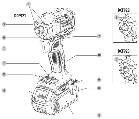 Components
- Trigger switch
- Forward/reverse button
- Anvil
- Battery release button
- Battery pack
- Worklight
- Mode selector
- Belt hook
- Screw
- Main handle
- Worklight switch
Fig. B

75–100% charged
![]()
51–74% charged

< 50% charged

Pack needs to be charged
Fig. C
 Charging
 Fully Charged
 Hot/Cold Pack Delay

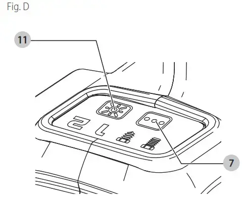
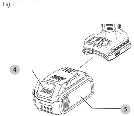
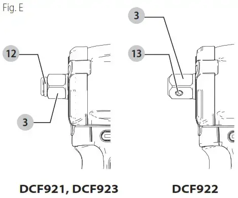
![]() WARNING: Read all safety warnings and all instructions. Failure to follow the warnings and instructions may result in electric shock, fire and/or serious injury.
WARNING: Read all safety warnings and all instructions. Failure to follow the warnings and instructions may result in electric shock, fire and/or serious injury.
![]() WARNING: To reduce the risk of injury, read the instruction manual.
WARNING: To reduce the risk of injury, read the instruction manual.
Intended Use
This impact wrench is designed for professional impact fastening and drilling applications. The impact function makes this tool particularly useful for driving fasteners in wood, metal and concrete.
DO nOT use under wet conditions or in presence of flammable liquids or gases.
DO nOT let children come into contact with the tool. Supervision is required when inexperienced operators use this tool.
Definitions: Safety Alert Symbols and Words
This instruction manual uses the following safety alert symbols and words to alert you to hazardous situations and your risk of personal injury or property damage.
![]() DANGER: Indicates an imminently hazardous situation which, if not avoided, will result in death or serious injury.
DANGER: Indicates an imminently hazardous situation which, if not avoided, will result in death or serious injury.
![]() WARNING: Indicates a potentially hazardous situation which, if not avoided, could result in death or serious injury.
WARNING: Indicates a potentially hazardous situation which, if not avoided, could result in death or serious injury.
![]() CAUTION: Indicates a potentially hazardous situation which, if not avoided, may result in minor or moderate injury.
CAUTION: Indicates a potentially hazardous situation which, if not avoided, may result in minor or moderate injury.
![]() (Used without word) Indicates a safety related message.
(Used without word) Indicates a safety related message.
NOTICE: Indicates a practice not related to personal injury which, if not avoided, may result in property damage.
GENERAL POWER TOOL SAFETY WARNINGS
![]() WARNING : Read all safety warnings, instructions, illustrations and specifications provided with this power tool. Failure to follow all instructions listed below may result in electric shock, fire and/or serious injury.
WARNING : Read all safety warnings, instructions, illustrations and specifications provided with this power tool. Failure to follow all instructions listed below may result in electric shock, fire and/or serious injury.
SAVE ALL WARNINGS AND INSTRUCTIONS FOR FUTURE REFERENCE.
The term “power tool” in the warnings refers to your mains‑operated (corded) power tool or battery‑operated (cordless) power tool.
- Work Area Safety
a ) Keep work area clean and well lit. Cluttered or dark areas invite accidents.
b ) Do not operate power tools in explosive atmospheres, such as in the presence of flammable liquids, gases or dust. Power tools create sparks which may ignite the dust or fumes.
c ) Keep children and bystanders away while operating a power tool. Distractions can cause you to lose control. - Electrical Safety
a ) Power tool plugs must match the outlet. Never modify the plug in any way. Do not use any adapter plugs with earthed (grounded) power tools. Unmodified plugs and matching outlets will reduce risk of electric shock.
b ) Avoid body contact with earthed or grounded surfaces, such as pipes, radiators, ranges and refrigerators. There is an increased risk of electric shock if your body is earthed or grounded.
c ) Do not expose power tools to rain or wet conditions. Water entering a power tool will increase the risk of electric shock.
d ) Do not abuse the cord. Never use the cord for carrying, pulling or unplugging the power tool. Keep cord away from heat, oil, sharp edges ormoving parts. Damaged or entangled cords increase the risk of electric shock.
e ) When operating a power tool outdoors, use an extension cord suitable for outdoor use. Use of a cord suitable for outdoor use reduces the risk of electric shock.
f ) If operating a power tool in a damp location is unavoidable, use a ground fault circuit interrupter (GFCI) protected supply. Use of a GFCIreduces the risk of electric hock. - Personal Safety
a ) Stay alert, watch what you are doing and use common sense when operating a power tool. Do not use a power tool while you are tired or under the influence of drugs, alcohol or medication. A moment of inattention while operating power tools may result in serious personal injury.
b ) Use personal protective equipment. Always wear eye protection. Protective equipment such as a dust mask, non‑skid safety shoes, hard hat, or hearing protection used for appropriate conditions will reduce personal injuries.
c ) Prevent unintentional starting. Ensure the switch is in the off‑position before connecting to power source and/or battery pack, picking up or carrying the tool. Carrying power tools with your finger on the switch or energizing power tools that have the switch on invites accidents.
d ) Remove any adjusting key or wrench before turning the power tool on. A wrench or a key left attached to a rotating part of the power tool may result in personal injury.
e ) Do not overreach. Keep proper footing and balance at all times. This enables better control of the power tool in unexpected situations.
f ) Dress properly. Do not wear loose clothing or jewelry. Keep your hair, clothing and gloves away from moving parts. Loose clothes, jewelry or long hair can be caught in moving parts.
g ) If devices are provided for the connection of dust extraction and collection facilities, ensure these are connected and properly used. Use of dust collection can reduce dust‑related hazards.
h ) Do not let familiarity gained from frequent use of tools allow you to become complacent and ignore tool safety principles. A careless action can cause severe injury within a fraction of a second. - Power Tool Use and Care
a ) Do not force the power tool. Use the correct power tool for your application. The correct power tool will do the job better and safer at the rate for which it was designed.
b ) Do not use the power tool if the switch does not turn it on and off. Any power tool that cannot be controlled with the switch is dangerous and must be repaired.
c ) Disconnect the plug from the power source and/ or remove the battery pack, if detachable, from the power tool before making any adjustments, changing accessories, or storing power tools. Such preventive safety measures reduce the risk of starting the power tool accidentally.
d ) Store idle power tools out of the reach of children and do not allow persons unfamiliar with the power tool or these instructions to operate the power tool. Power tools are dangerous in the hands of untrained users.
e ) Maintain power tools and accessories. Check for misalignment or binding of moving parts, breakage of parts and any other condition that may affect the power tool’s operation. If damaged, have the power tool repaired before use. Many accidents are caused by poorly maintained power tools.
f ) Keep cutting tools sharp and clean. Properly maintained cutting tools with sharp cutting edges are less likely to bind and are easier to control.
g ) Use the power tool, accessories and tool bits etc. in accordance with these instructions, taking into account the working conditions and the work to be performed. Use of the power tool for operations different from those intended could result in a hazardous situation.
h ) Keep handles and grasping surfaces dry, clean and free from oil and grease. Slippery handles and grasping surfaces do not allow for safe handling and control of the tool in unexpected situations. - Battery Tool Use and Care
a ) Recharge only with the charger specified by the manufacturer. A charger that is suitable for one type of battery pack may create a risk of fire when used with another battery pack.
b ) Use power tools only with specifically designated battery packs. Use of any other battery packs may create a risk of injury and fire.
c ) When battery pack is not in use, keep it away from other metal objects, like paper clips, coins, keys, nails, screws or other small metal objects,that can make a connection from one terminal to another. Shorting the battery terminals together may cause burns or a fire.
d ) Under abusive conditions, liquid may be ejected from the battery; avoid contact. If contact accidentally occurs, flush with water. If liquid contacts eyes, additionally seek medical help. Liquid ejected from the battery may cause irritation or burns.
e ) Do not use a battery pack or tool that is damaged or modified. Damaged or modified batteries may exhibit unpredictable behavior resulting in fire, explosion or risk of injury.
f ) Do not expose a battery pack or tool to fire or excessive temperature. Exposure to fire or temperature above 265 °F (130 °C) may cause explosion.
g ) Follow all charging instructions and do not charge the battery pack or tool outside the temperature range specified in the instructions. Charging improperly or at temperatures outside the specified range may damage the battery and increase the risk of fire. - Service
a ) Have your power tool serviced by a qualified repair person using only identical replacement parts. This will ensure that the safety of the power tool is maintained.
b ) Never service damaged battery packs. Service of battery packs should only be performed by the manufacturer or authorized service providers.
Impact Wrench Safety Warnings – All Operations
• Hold the power tool by insulated gripping surfaces, when performing an operation where the fastener may contact hidden wiring. Fasteners contacting a “live” wire may make exposed metal parts of the power tool “live” and could give the operator an electric shock.
• Wear ear protectors during use. Exposure to noise can cause hearing loss.
 WARNING: Impact wrenches are not torque wrenches. DO NOT use this tool for tightening fasteners to specified torques. An independent, calibrated torque easurement device such as a torque wrench should be used when under tightenedor over tightened fasteners can lead to the failure of the joint.
• Wear safety goggles or other eye protection. Hammering and drilling operations cause chips to fly. Flying particles can cause permanent eye damage.
• Do not operate this tool for long periods of time. Vibration caused by tool action may be harmful to your hands and arms. Use gloves to provide extra cushion and limit exposure by taking frequent rest periods.
• Accessories and tools get hot during operation. Wear gloves when touching them.
Additional Safety Information
![]() WARNING: Never modify the power tool or any part of it. Damage or personal injury could result.
WARNING: Never modify the power tool or any part of it. Damage or personal injury could result.
![]() WARNING: ALWAYS use safety glasses. Everyday eyeglasses are NOT safety glasses. Also use face or dust mask if cutting operation is dusty. ALWAYS WEAR
WARNING: ALWAYS use safety glasses. Everyday eyeglasses are NOT safety glasses. Also use face or dust mask if cutting operation is dusty. ALWAYS WEAR
CERTIFIED SAFETY EQUIPMENT:
- ANSI Z87.1 eye protection (CAN/CSA Z94.3),
- ANSI S12.6 (S3.19) hearing protection,
- NIOSH/OSHA/MSHA respiratory protection.
WARNING: Some dust created by power sanding, sawing, grinding, drilling, and other construction activities contains chemicals known to the State of California to cause cancer, birth defects or other reproductive harm. Some examples of these chemicals are: - lead from lead‑based paints,
- crystalline silica from bricks and cement and other masonry products, and
- arsenic and chromium from chemically‑treated lumber.
Your risk from these exposures varies, depending on how often you do this type of work. To reduce your exposure to these chemicals: work in a well ventilated area, and work with approved safety equipment, such as those dust masks that are specially designed to filter out microscopic particles. - Wear protective clothing and wash exposed areas with soap and water. Allowing dust to get into your mouth, eyes, or lay on the skin may promote absorption of armful hemicals. Direct particles away from face and body.
- Use the appropriate dust extractor vacuum to remove the vast majority of static and airborne dust. Failure to remove static and airborne dust could contaminate the working environment or pose an increased health risk to the operator and those in close proximity.
- Use clamps or other practical ways to secure and support the workpiece to a stable platform. Holding the work by hand or against your body is unstable and may lead to loss of control and injury.
- Air vents often cover moving parts and should be avoided. Loose clothes, jewelry or long hair can be caught in moving parts.
CAUTION: When not in use, place tool on its side on a stable surface where it will not cause a tripping or falling hazard. Some tools with large battery packs will stand upright on the battery pack but may be easily knocked over. The label on your tool may include the following symbols. The symbols and their definitions are as follows:
V ……………………. volts
Hz ………………….. hertz
min ………………… minutes
or DC …… direct current
![]() …………………. Class I Construction (grounded)
…………………. Class I Construction (grounded)
 …/min ………….. per minute
BPM ……………….. beats per minute
IPM ………………… impacts per minute
OPM ……………….. oscillations per minute
RPM ……………….. revolutions per minute
sfpm ………………. surface feet per minute
SPM ……………….. strokes per minute
A ……………………. amperes
W …………………… watts
Wh …………………. watt hours
Ah ………………….. amp hours
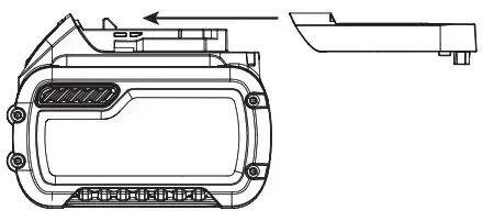 ……….. alternating current
 …. alternating or direct current
 …………………. Class II Construction (double insulated)
no ………………….. no load speed
n ……………………. rated speed
PSI………………….. pounds per square inch
 …………………. earthing terminal
![]() ………………… safety alert symbol
………………… safety alert symbol
 ………………… visible radiation
 ………………… wear respiratory protection
 ………………… wear eye protection
 ………………… wear hearing protection
.![]() ……………….. read all documentation
……………….. read all documentation
BATTERIES AND CHARGERS
The battery pack is not fully charged out of the carton.
Before using the battery pack and charger, read the safety instructions below and then follow charging procedures outlined. When ordering replacement battery packs, be sure to include the catalog number and voltage.
READ ALL INSTRUCTIONS
Important Safety Instructions for All Battery Packs
![]() WARNING: Read all safety warnings, instructions, and cautionary markings for the battery pack, charger and product. Failure to follow the warnings and instructions may result in electric shock, fire and/or serious injury.
WARNING: Read all safety warnings, instructions, and cautionary markings for the battery pack, charger and product. Failure to follow the warnings and instructions may result in electric shock, fire and/or serious injury.
- Do not charge or use the battery pack in explosive atmospheres, such as in the presence of flammable liquids, gases or dust. Inserting or removing the battery pack from the charger may ignite the dust or fumes.
- NEVER force the battery pack into the charger. DO NOT modify the battery pack in any way to fit into a non‑compatible charger as battery pack may rupture causing serious personal injury. Consult the chart at the end of this manual for compatibility of batteries and chargers.
- Charge the battery packs only in DeWALT chargers.
- DO NOT splash or immerse in water or other liquids.
- DO NOT allow water or any liquid to enter battery pack.
- Do not store or use the tool and battery pack in locations where the temperature may reach or exceed 104 °F (40 °C) (such as outside sheds or metal buildings in summer). For best life store battery packs in a cool, dry location.
NOTE: Do not store the battery packs in a tool with the trigger switch locked on. Never tape the trigger switch in the ON position. - Do not incinerate the battery pack even if it is severely damaged or is completely worn out. The battery pack can explode in a fire. Toxic fumes and materials are created when lithium‑ion battery packs are burned.
- Do not expose a battery pack or appliance to fire or excessive temperature. Exposure to fire or temperature above 265 °F (130 °C) may cause explosion.
- If battery contents come into contact with the skin, immediately wash area with mild soap and water. If battery liquid gets into the eye, rinse water over the open eye for 15 minutes or until irritation ceases. If medical attention is needed, the battery electrolyte is composed of a mixture of liquid organic carbonates and lithium salts.
- Contents of opened battery cells may cause respiratory irritation. Provide fresh air. If symptoms persist, seek medical attention.
- Battery liquid may be flammable if exposed to spark or flame.
- Never attempt to open the battery pack for any reason. If the battery pack case is cracked or damaged, do not insert into the charger. Do not crush, drop or damage the battery pack. Do not use a battery pack or charger that has received a sharp blow, been dropped, run over or damaged in any way (e.g., pierced with a nail, hit with a hammer, stepped on). Damaged battery packs should be returned to the service center for recycling.
Storage Recommendations
The best storage place is one that is cool and dry, away from direct sunlight and excess heat or cold. Store the fully charged battery pack out of the charger.
Battery Pack Cleaning Instructions
Dirt and grease may be removed from the exterior of the battery pack using a cloth or soft non‑metallic brush. Do not use water or any cleaning solutions.
Fuel Gauge Battery Packs (Fig. B)
Some battery packs include a fuel gauge. When the fuel gauge button is pressed and held, the LED lights will indicate the approximate level of charge remaining. This does not indicate tool functionality and is subject to variation based on product components, temperature, and end‑user application.
Transportation
![]() WARNING: Fire hazard. Do not store, carry, or transport the battery pack so that metal objects can contact exposed battery terminals. For example, do not place the battery pack in aprons, pockets, tool boxes, product kit boxes, drawers, etc., with loose nails, screws, keys, coins, hand tools, etc. When transporting individual battery packs, make sure that the battery terminals are protected and well insulated from materials that could contact them and cause a short circuit. NOTE: Li‑ion battery packs should not be put in checked baggage on airplanes and must be properly protected from short circuits if they are in carry‑on baggage. shipping the DeWALT FlEXVOlT™ Battery Pack
WARNING: Fire hazard. Do not store, carry, or transport the battery pack so that metal objects can contact exposed battery terminals. For example, do not place the battery pack in aprons, pockets, tool boxes, product kit boxes, drawers, etc., with loose nails, screws, keys, coins, hand tools, etc. When transporting individual battery packs, make sure that the battery terminals are protected and well insulated from materials that could contact them and cause a short circuit. NOTE: Li‑ion battery packs should not be put in checked baggage on airplanes and must be properly protected from short circuits if they are in carry‑on baggage. shipping the DeWALT FlEXVOlT™ Battery Pack
The DeWALT FLEXVOLT™ battery pack has a battery cap that should be used when shipping the battery pack.

Attach the cap to the battery pack to ready it for shipping.
This converts the battery pack to three separate 20V batteries. The three batteries have the Watt hour rating labeled “Shipping” on the battery pack. If shipping without
the cap or in a tool, the pack is one battery at the Watt hour rating labeled “Use”.
Example battery pack label:
USE: 120 Wh SHIPPING: 3 x 40 Wh
In this example, the battery pack is three batteries with 40 Watt hours each when using the cap. Otherwise, the battery pack is one battery with 120 Watt hours.

The RBRC® Seal
Please take your spent battery packs to an authorized DeWALT service center or to your local retailer for recycling. In some areas, it is illegal to place spent battery
packs in the trash. You may also contact your local recycling center for information on where to drop off the spent battery pack. Do not place in curbside recycling. For more
information visit www.call2recycle.org. or call the toll free number in the RBRC® Seal. RBRC® is a registered trademark of Call 2 Recycle, Inc.
Important Safety Instructions for All Battery Chargers
WARNING: Read all safety warnings, instructions, and cautionary markings for the battery pack, charger and product. Failure to follow the warnings and instructions may result in electric shock, fire and/or serious injury.
- DO NOT attempt to charge the battery pack with any chargers other than a DeWALT charger. DeWALT chargers and battery packs are specifically designed to work together.
- These chargers are not intended for any uses other than charging DeWALT rechargeable battery packs. Charging other types of battery packs may cause them to overheat and burst, resulting in personal injury, property damage, fire, electric shock or electrocution.
- Do not expose the charger to rain or snow.
- Do not allow water or any liquid to enter charger.
- Pull by the plug rather than the cord when disconnecting the charger. This will reduce the risk of damage to the electric plug and cord.
- Make sure that the cord is located so that it will not be stepped on, tripped over or otherwise subjected to damage or stress.
- Do not use an extension cord unless it is absolutely necessary. Use of improper extension cord could result in risk of fire, electric shock or electrocution.
- When operating a charger outdoors, always provide a dry location and use an extension cord suitable for outdoor use. Use of a cord suitable for outdoor use reduces the risk of electric shock.
- An extension cord must have adequate wire size (AWG or American Wire Gauge) for safety. The smaller the gauge number of the wire, the heavier the cord and thus the greater its capacity. An undersized cord will cause a drop in line voltage resulting in loss of power and overheating. The following table shows the correct size to use depending on total length of all extension cords plugged together, and nameplate ampere rating. If in doubt, use the next heavier gauge.
Minimum gauge for Cord sets
| Volts | Total length of Cord in Feet(meters) | ||||
| 120V | 25 (7.6) | 50 (15.2) | 100 (30.5) | 150 (45.7) | |
| Ampere Rating | American Wire gauge | ||||
| More Than | Not MoreThan | ||||
| 0 | 6 | 18 | 16 | 16 | 14 |
| 6 | 10 | 18 | 16 | 14 | 12 |
| 10 | 12 | 16 | 16 | 14 | 12 |
| 12 | 16 | 14 | 12 | Not Recommended | |
- Do not place any object on top of the charger or place the charger on a soft surface that might block the ventilation slots and result in excessive internal heat. Place the charger in a position away from any heat source. The charger is ventilated through slots in the top and the bottom of the housing.
- Do not operate the charger with a damaged cord or plug. Have them replaced immediately.
- Do not operate the charger if it has received a sharp blow, been dropped or otherwise damaged in any way. Take it to an authorized service center.
- Do not disassemble the charger; take it to an authorized service center when service or repair is required. Incorrect reassembly may result in a risk of electric shock, electrocution or fire.
- The charger is designed to operate on standard 120V household electrical power. Do not attempt to use it on any other voltage. This does not apply to the vehicular charger.
- Foreign materials of a conductive nature, such as, but not limited to, grinding dust, metal chips, steel wool, aluminum foil or any buildup of metallic particles should be kept away from the charger cavities and ventilation slots.
- Always unplug the charger from the power supply when there is no battery pack in the cavity.
Charging a Battery (Fig. C)
- Plug the charger into an appropriate outlet.
- Insert and fully seat battery pack. The red charging light(s) will continuously blink while charging.
- Charging is complete when the red charging light(s) remain(s) continuously ON. Battery pack can be left in charger or removed. Some chargers require the battery pack release button to be pressed for removal.
WARNING: Only charge batteries in air temperature over 40 ° F (4.5 ° C) and below 104 ° F (+40 ° C). - Charger will not charge a faulty battery pack, which may be indicated by the charging light(s) staying OFF. Take charger and battery pack to an authorized service center
if light(s) stay(s) OFF.
nOTE: Refer to label near charging light(s) on charger for blink patterns. Older chargers may have additional information and/or may not have a yellow indicator light.
nOTE: To remove the battery pack, some chargers require the battery pack release button to be pressed.
hot/Cold Pack Delay
When the charger detects a battery pack that is too hot or too cold, it automatically starts a Hot/Cold Pack Delay, suspending charging until the battery pack has reached an
appropriate temperature. The charger then automatically switches to the pack charging mode. This feature ensures maximum battery pack life.
A cold battery pack may charge at a slower rate than a warm battery pack.
The hot/cold pack delay will be indicated by the red light(s) continuing to blink but with the yellow light continuously ON. Once the battery pack has reached an appropriate
temperature, the yellow light will turn OFF and the charger will resume the charging procedure.
DCB118 and DCB1112 Chargers
The DCB118 and DCB1112 chargers are equipped with an internal fan designed to cool the battery pack. The fan will turn on automatically when the battery pack needs to
be cooled.
Never operate the charger if the fan does not operate properly or if ventilation slots are blocked. Do not permit foreign objects to enter the interior of the charger.
Electronic Protection System
Li‑Ion tools are designed with an Electronic Protection System that will protect the battery pack against overloading, overheating or deep discharge. The tool will automatically
turn off and the battery pack will need to be recharged.
Important Charging Notes
- Longest life and best performance can be obtained if the battery pack is charged when the air temperature is between 65 °F – 75 °F (18 ° C– 24 °C). DO NOT charge
when the battery pack is below +40 °F (+4.5 °C), or above +104 °F (+40 °C). This is important and will prevent serious damage to the battery pack. - The charger and battery pack may become warm to the touch while charging. This is a normal condition, and does not indicate a problem. To facilitate the cooling of the battery pack after use, avoid placing the charger or battery pack in a warm environment such as in a metal shed or an uninsulated trailer.
- If the battery pack does not charge properly:a. Check operation of receptacle by plugging in a lamp or other appliance;
b. Check to see if receptacle is connected to a light switch which turns power off when you turn out the lights;
c. If charging problems persist, take the tool, battery pack and charger to your local service center. - You may charge a partially used pack whenever you desire with no adverse effect on the battery pack.
Charger Cleaning Instructions
WARNING: Shock hazard. Disconnect the charger from the AC outlet before cleaning. Dirt and grease may be removed from the exterior of the charger using a cloth or soft non‑metallic brush. Do not use water or any cleaning solutions.
Wall Mounting
Some DeWALT chargers are designed to be wall mountable or to sit upright on a table or work surface. If wall mounting, locate the charger within reach of an electrical outlet, and away from a corner or other obstructions which may impede air flow. Use the back of the charger as a template for the location of the mounting screws on the wall. Mount the charger securely using drywall screws (purchased separately) at least 1” (25.4 mm) long, with a screw head diameter of 0.28–0.35” (7–9 mm), screwed into wood to an optimal depth leaving approximately 7/32” (5.5 mm) of the screw exposed. Align the slots on the back of the charger with the exposed screws and fully engage them in the slots.
SAVE THESE INSTRUCTIONS FOR FUTURE USE ASSEMBLY AND ADJUSTMENTS
![]() WARNING: To reduce the risk of serious personal injury, turn unit off and remove the battery packbefore making any adjustments or removing/ installing attachments or accessories. An accidental start‑up can cause injury.
WARNING: To reduce the risk of serious personal injury, turn unit off and remove the battery packbefore making any adjustments or removing/ installing attachments or accessories. An accidental start‑up can cause injury.
Anvil (Fig. E)
![]() WARNING: Use only impact accessories. Non‑impact accessories may break and cause a hazardous condition. Inspect accessory prior to use to ensure that it contains no cracks.
WARNING: Use only impact accessories. Non‑impact accessories may break and cause a hazardous condition. Inspect accessory prior to use to ensure that it contains no cracks.
![]() CAUTION: Inspect anvils, detent pins, and hog rings prior to use. Missing or damaged items should be replaced before use.
CAUTION: Inspect anvils, detent pins, and hog rings prior to use. Missing or damaged items should be replaced before use.
Place the switch in the locked off (center) position or remove battery pack before changing accessories.
Anvil with Detent Pin (Fig. E) DCF922
To install an accessory on the anvil, align the hole in the side of the accessory with the detent pin 13 on the anvil 3 . Press the accessory on until the detent pin engages in the hole. Depression of detent pin may be necessary to aid installation of accessory.To remove an accessory, depress the detent pin through the hole and pull the accessory off.
Anvil With Hog Ring (Fig. E) DCF921, DCF923 To install an accessory on the hog ring anvil, firmly push accessory onto the anvil 3 . The hog ring 12 compresses to allow the accessory to slide on. After accessory is installed, the hog ring applies pressure to help provide accessory retention. To remove an accessory, grasp the accessory and firmly pull it off.
Belt Hook (Fig. A)
Included with Some Models
![]() WARNING: To reduce the risk of serious personal injury, ONLY use the tool’s belt hook to hang the tool from a work belt. DO NOT use the belt hook for tethering or securing the tool to a person or object during use. DO NOT suspend tool overhead or suspend objects from the belt hook.
WARNING: To reduce the risk of serious personal injury, ONLY use the tool’s belt hook to hang the tool from a work belt. DO NOT use the belt hook for tethering or securing the tool to a person or object during use. DO NOT suspend tool overhead or suspend objects from the belt hook.
![]() WARNING: To reduce the risk of serious personal injury, ensure the screw holding the belt hook is secure.
WARNING: To reduce the risk of serious personal injury, ensure the screw holding the belt hook is secure.
iMPORTAnT: When attaching or replacing a belt hook, use only the screw that is provided. Be sure to securely tighten the screw.
A belt hook 8 can be be attached to either side of the tool using only the screw 9 provided, to accommodate left‑ or right‑handed users. If the belt hook is not desired at all, it can be removed from the tool.
To move the belt hook, remove the screw 9 that holds it in place then reassemble on the opposite side. Be sure to securely tighten the screw.
Mode Selector (Fig. A, D)
Your tool is equipped with a mode selector 7 which allows you to select one of two speeds, Timber Screw™ mode, or Precision Wrench™ mode. Select the mode based on the
maximum speed/torque needed and control the speed of the tool using the variable speed trigger switch 1 .
 Timber Screw™ Mode (Fig. D)
Timber Screw™ mode optimizes tool performance to help increase the speed of wood driving applications such as with lag bolts, lag screws and structural wood screws.
![]() Precision Wrench™ Mode (Fig. D)
Precision Wrench™ Mode (Fig. D)
In addition to normal impacting modes, this tool features the Precision Wrench™ mode which grants the user greater control in both fastening and loosening applications.
When set in forward, the tool will fasten at 2500 RPM until impact begins. The tool will then pause for 0.5 seconds before continuing to impact at a rate of 3550 IPM, providing the user with greater control and reducing the chance of overtightening or damaging material. When set in reverse, the tool will impact at a normal speed and rate of 3550 IPM. Upon sensing that the fastener has broken free, the tool will cease to impact and will reduce speed to help prevent “run‑off” of loose hardware.
specifications
| Mode | Application | RPM |
| Precision Wrench™ | Precision Wrench™ | 0‑2500 forward 0‑2500 reverse |
| Timber Screw™ | Timber Screw™ | 0‑2500 forward 0‑2500 reverse |
| Speed 1 | Low Speed Impacting | 0‑1400 forward 0‑2500 reverse |
| Speed 2 | High Speed Impacting | 0‑2500 forward 0‑2500 reverse |
OPERATION
WARNING: To reduce the risk of serious personal injury, turn unit off and remove the battery pack before making any adjustments or removing/ installing attachments or accessories. An accidental start‑up can cause injury.
Installing and Removing the Battery Pack (Fig. F)
nOTE: For best results, make sure your battery pack is fully charged.
To install the battery pack 5 into the tool handle, align the battery pack with the rails inside the tool’s handle and slide it into the handle until the battery pack is firmly seated in the tool and ensure that it does not disengage. To remove the battery pack from the tool, press the release button 4 and firmly pull the battery pack out of the tool handle. Insert it into the charger as described in the charger section of this manual.
Proper Hand Position (Fig. G)
![]() WARNING : To reduce the risk of serious personal injury, ALWAYS use proper hand position as shown.
WARNING : To reduce the risk of serious personal injury, ALWAYS use proper hand position as shown.
![]() WARNING: To reduce the risk of serious personal injury, ALWAYS hold securely in anticipation of a sudden reaction.
WARNING: To reduce the risk of serious personal injury, ALWAYS hold securely in anticipation of a sudden reaction.
Proper hand position requires one hand on the main handle 10 .
Variable Speed Trigger Switch (Fig. A)
To turn the tool on, squeeze the trigger switch 1 . To turn the tool off, release the trigger switch. Your tool is equipped with a brake. The anvil will stop when the trigger switch is fully released. The variable speed switch enables you to select the best speed for a particular application. The more you squeeze the trigger, the faster the tool will operate. For maximum tool life, use variable speed only for starting holes or fasteners. nOTE: Continuous use in variable speed range is not recommended. It may damage the switch and should be avoided.
Forward/Reverse Control Button (Fig. A)
A forward/reverse control button 2 determines the direction of the tool and also serves as a lock‑off button.
To select forward rotation, release the trigger switch and depress the forward/reverse control button on the right side of the tool.
To select reverse, release the trigger switch and depress the forward/reverse control button on the left side of the tool. The center position of the control button locks the tool in the off position. When changing the position of the control button, be sure the trigger is released.
NOTE: The first time the tool is run after changing the direction of rotation, you may hear a click on start up. This is normal and does not indicate a problem.
Worklight (Fig. A, D)
The worklight 6 is activated when the variable speed trigger 1 is depressed. Pressing the worklight switch 11 repeatedly will cycle through low illumination, high illumination, and off. NOTE: The worklight is for lighting the immediate work surface and is not intended to be used as a flashlight.
Usage (Fig. A)
![]() CAUTION: Ensure fastener and/or system will withstand the level of torque generated by the tool. Excessive torque may cause breakage and possible personal injury.
CAUTION: Ensure fastener and/or system will withstand the level of torque generated by the tool. Excessive torque may cause breakage and possible personal injury.
- Place the accessory on the fastener head. Keep the tool pointed straight at the fastener.
- Press variable speed trigger switch 1 to start operation. Release variable speed trigger switch to stop operation. Always check torque with a torque wrench, as the fastening torque is affected by many factors including the following:
‑ Voltage: Low voltage, due to a nearly discharged battery, will reduce fastening torque.
‑ Accessory size: Failure to use the correct accessory size will cause a reduction in fastening torque.
‑ Bolt size: Larger bolt diameters generally require higher fastening torque. Fastening torque will also vary according to length, grade, and torque coefficient.
‑ Bolt: Ensure that all threads are free of rust and other debris to allow proper fastening torque.
‑ Material: The type of material and surface finish of the material will affect fastening torque.
‑ Fastening time: Longer fasten ing time results in increased fastening torque. Using a longer fastening time than recommended could cause the fasteners to be overstressed, stripped or damaged.
specifications
| Max. fastening torque | 300 ft‑lbs, 406 Nm (Speed 2, Timber Screw™, Precision Wrench™) 150 ft‑lbs, 203 Nm (Speed 1) |
| Max. breakaway torque | 450 ft‑lbs, 610 Nm (all modes) |
| No load speed | 0‑2500 rpm |
| Impacts per minute | 0‑3550 ipm |
| Length | 4.95″ (126 mm) |
| Weight | 2.47 lbs (1.1 kg) |
MAINTENANCE
WARNING: To reduce the risk of serious personal injury, turn unit off and remove the battery pack before making any adjustments or removing/ installing attachments or accessories. An accidental start‑up can cause injury.
Your DeWALT power tool has been designed to operate over a long period of time with a minimum of maintenance. Continuous satisfactory operation depends upon proper tool care and regular cleaning.
Cleaning
![]() WARNING: Blow dirt and dust out of all air vents with clean, dry air at least once a week. To minimize the risk of eye injury, always wear ANSI Z87.1 approved eye protection when performing this procedure.
WARNING: Blow dirt and dust out of all air vents with clean, dry air at least once a week. To minimize the risk of eye injury, always wear ANSI Z87.1 approved eye protection when performing this procedure.
![]() WARNING: Never use solvents or other harsh chemicals for cleaning the non‑metallic parts of the tool. These chemicals may weaken the plastic materials used in these parts. Use a cloth dampened only with water and mild soap. Never let any liquid get inside the tool; never immerse any part of the tool into a liquid.
WARNING: Never use solvents or other harsh chemicals for cleaning the non‑metallic parts of the tool. These chemicals may weaken the plastic materials used in these parts. Use a cloth dampened only with water and mild soap. Never let any liquid get inside the tool; never immerse any part of the tool into a liquid.
Accessories
![]() WARNING: Since accessories, other than those offered by DeWALT, have not been tested with this product, use of such accessories with this tool could be hazardous. To reduce the risk of injury, only DeWALT recommended accessories should be used with this product.
WARNING: Since accessories, other than those offered by DeWALT, have not been tested with this product, use of such accessories with this tool could be hazardous. To reduce the risk of injury, only DeWALT recommended accessories should be used with this product.
Recommended accessories for use with your tool are available at extra cost from your local dealer or authorized service center. If you need assistance in locating any accessory, please contact DeWALT call 1‑800‑4‑DeWALT (1‑800‑433‑9258) or visit our website:www.dewalt.com.
Impact Accessories
![]() WARNING: Use only impact accessories. Non‑impact accessories may break and cause a hazardous condition. Inspect accessories prior to use to ensure that they contain no cracks.
WARNING: Use only impact accessories. Non‑impact accessories may break and cause a hazardous condition. Inspect accessories prior to use to ensure that they contain no cracks.
Repairs
The charger and battery pack are not serviceable. There are no serviceable parts inside the charger or battery pack.
![]() WARNING: To assure product SAFETY and RELIABILITY, repairs, maintenance and adjustment (including brush inspection and replacement, when applicable) should be performed by a DeWALT factory service center or a DeWALT authorized service center. Always use identical replacement parts.
WARNING: To assure product SAFETY and RELIABILITY, repairs, maintenance and adjustment (including brush inspection and replacement, when applicable) should be performed by a DeWALT factory service center or a DeWALT authorized service center. Always use identical replacement parts.
Register Online
Thank you for your purchase. Register your product now for:
- WARRAnTY sERViCE: Registering your product will help you obtain more efficient warranty service in case there is a problem with your product.
- COnFiRMATiOn OF OWnERshiP: In case of an insurance loss, such as fire, flood or theft, your registration of ownership will serve as your proof of purchase.
- FOR YOUR sAFETY: Registering your product will allow us to contact you in the unlikely event a safety notification is required under the Federal Consumer Safety Act.
- Register online at www.dewalt.com
Three Year Limited Warranty
For warranty terms, go to https://www.dewalt.com/Legal/Warranty/3‑Year‑Limited‑Warranty.
To request a written copy of the warranty terms, contact: Customer Service at DeWALT Industrial Tool Co., 701 East Joppa Road, Towson, MD 21286 or call 1‑800‑4‑DeWALT (1‑800‑433‑9258).
lATin AMERiCA: This warranty does not apply to products sold in Latin America. For products sold in Latin America, see country specific warranty information contained in
the packaging, call the local company or see website for warranty information.
FREE WARning lABEl REPlACEMEnT: If your warning labels become illegible or are missing, call 1‑800‑4‑DeWALT (1‑800‑433‑9258) for a free replacement.
Compatible battery packs and chargers
| 20V Max* li‑ion | Battery Packs | DCB200, DCB201, DCB203, DCB204, DCB204BT**, DCB205, DCB205BT**, DCB206, DCB208, DCB210, DCB230, DCB240 |
| Chargers | DCB103, DCB104, DCB107, DCB112, DCB113, DCB115, DCB118, DCB132, DCB1106, DCB1112 |
| 60V Max* li‑ion | Battery Packs | DCB606, DCB609, DCB612 |
| Chargers | DCB103, DCB104, DCB107, DCB112, DCB113, DCB115, DCB118, DCB132, DCB1106, DCB1112 |
* Maximum initial battery voltage (measured without a workload) is 20, 60 or 120 volts. Nominal voltage is 18, 54 or 108. (120V Max* is based on using 2 DeWALT 60V Max* lithium‑ion batteries combined.)
**BT ‑ Bluetooth®
NOTE: The Bluetooth® word mark and logos are registered trademarks owned by the Bluetooth®, SIG, Inc. and any use of such marks by DeWALT is under license. Other trademarks and trade names are those of their respective owners.
![]() WARNING: Use of any other battery packs may create a risk of injury and fire.
WARNING: Use of any other battery packs may create a risk of injury and fire.
DeWALT Industrial Tool Co. 701 East Joppa Road, Towson, MD 21286
Copyright © 2021
The following are trademarks for one or more DeWALT power tools: the yellow and black color scheme, the “D” shaped air
intake grill, the array of pyramids on the handgrip, the kit box configuration, and the array of lozenge‑shaped humps on the
surface of the tool.
N909768
DEWALT Kerosene Forced-air Heater
DEWALT Kerosene Forced-air Heater
NEVER LEAVE THE HEATER UNATTENDED WHILE BURNING!
If you have questions or comments, contact us.
Pour toute question ou tout commentaire, nous contacter.
- 855-805-5745
- www.DEWALT.com
DXH80KTHC, DXH140KTHC, DXH210KTHCX
SAVE THESE INSTRUCTIONS
 WARNING: READ INSTRUCTIONS CAREFULLY: Read and follow all instructions. Place instructions in a safe place for future reference. Do not allow anyone who has not read these instructions to assemble, adjust or operate the heater.
Definitions: Safety Guidelines
The definitions below describe the level of severity for each signal word. Please read the manual and pay attention to these symbols.
![]() DANGER: Indicates an imminently hazardous situation that, if not avoided, will result in death or serious injury.
DANGER: Indicates an imminently hazardous situation that, if not avoided, will result in death or serious injury.
 WARNING: Indicates a potentially hazardous situation that, if not avoided, could result in death or serious injury.
![]() CAUTION: Indicates a potentially hazardous situation that, if not avoided, may result in minor or moderate injury.
CAUTION: Indicates a potentially hazardous situation that, if not avoided, may result in minor or moderate injury.
![]() NOTICE: Indicates a practice not related to personal injury which, if not avoided, may result in property damage.
NOTICE: Indicates a practice not related to personal injury which, if not avoided, may result in property damage.
![]() WARNING: FIRE BURN, INHALATION, AND EXPLOSION HAZARD. KEEP SOLID COMBUSTIBLES, SUCH AS BUILDING MATERIALS, PAPER, OR CARDBOARD, A SAFE DISTANCE AWAY FROM THE HEATER AS RECOMMENDED BY THE INSTRUCTIONS. NEVER USE THE HEATER IN SPACES THAT DO OR MAY CONTAIN VOLATILE OR AIRBORNE COMBUSTIBLES, OR PRODUCTS SUCH AS GASOLINE, SOLVENTS, PAINT THINNER, DUST PARTICLES OR UNKNOWN CHEMICALS.
WARNING: FIRE BURN, INHALATION, AND EXPLOSION HAZARD. KEEP SOLID COMBUSTIBLES, SUCH AS BUILDING MATERIALS, PAPER, OR CARDBOARD, A SAFE DISTANCE AWAY FROM THE HEATER AS RECOMMENDED BY THE INSTRUCTIONS. NEVER USE THE HEATER IN SPACES THAT DO OR MAY CONTAIN VOLATILE OR AIRBORNE COMBUSTIBLES, OR PRODUCTS SUCH AS GASOLINE, SOLVENTS, PAINT THINNER, DUST PARTICLES OR UNKNOWN CHEMICALS.
![]() WARNING: GENERAL HAZARDS
WARNING: GENERAL HAZARDS
FAILURE TO COMPLY WITH THE PRECAUTIONS AND INSTRUCTIONS PROVIDED WITH THIS HEATER, CAN RESULT IN DEATH, SERIOUS BODILY INJURY AND PROPERTY LOSS OR DAMAGE FROM HAZARDS OF FIRE, EXPLOSION, BURN, ASPHYXIATION, CARBON MONOXIDE POISONING, AND/OR ELECTRICAL SHOCK. ONLY PERSONS WHO CAN UNDERSTAND AND FOLLOW THE INSTRUCTIONS SHOULD USE OR SERVICE THIS HEATER. IF YOU NEED ASSISTANCE OR HEATER INFORMATION SUCH AS AN INSTRUCTIONS MANUAL, LABELS, ETC., CONTACT THE MANUFACTURER. SAVE THESE INSTRUCTIONS FOR FUTURE REFERENCE.
![]() WARNING: Fuels used in liquefied propane gas appliances, and the products of combustion of such fuel, can expose you to chemicals including benzene, which is known to the State of California to cause cancer and cause birth defects or other reproductive harm. For more information visit www.P65Warnings.ca.gov.
WARNING: Fuels used in liquefied propane gas appliances, and the products of combustion of such fuel, can expose you to chemicals including benzene, which is known to the State of California to cause cancer and cause birth defects or other reproductive harm. For more information visit www.P65Warnings.ca.gov.
![]() WARNING: This product can expose you to chemicals including lead and lead compounds, which are known to the State of California to cause cancer and birth defects or other reproductive harm. Wash your hands after handling this product. For more information visit www.P65Warnings.ca.gov.
WARNING: This product can expose you to chemicals including lead and lead compounds, which are known to the State of California to cause cancer and birth defects or other reproductive harm. Wash your hands after handling this product. For more information visit www.P65Warnings.ca.gov.
![]() WARNING: CARBON MONOXIDE CAN KILL YOU USING A PORTABLE HEATER IN AN ENCLOSED AREA CAN PRODUCE DEADLY CARBON MONOXIDE.
WARNING: CARBON MONOXIDE CAN KILL YOU USING A PORTABLE HEATER IN AN ENCLOSED AREA CAN PRODUCE DEADLY CARBON MONOXIDE.
![]() WARNING: NOT FOR HOME OR RECREATIONAL VEHICLE USE.
WARNING: NOT FOR HOME OR RECREATIONAL VEHICLE USE.
This is an unvented gas-fired portable heater. It uses air (oxygen) from the area in which it is used. Adequate combustion and ventilation air must be provided. Refer to page 4.
![]() WARNING:
WARNING:
- DO NOT USE GASOLINE, NAPHTHA, OR VOLATILE FUELS.
- STOP THE HEATER AND ALLOW IT TO COOL BEFORE ADDING FUELS.
- ALWAYS FILL OUTDOORS AWAY FROM OPEN FLAME.
- DO NOT USE EXTERNAL FUEL SOURCES.
- DO NOT OPERATE A HEATER WHERE FLAMMABLE LIQUIDS OR VAPORS MAY BE PRESENT.
- DO NOT START THE HEATER WHEN THE CHAMBER IS HOT.
- DO NOT START THE HEATER WHEN EXCESS FUEL HAS ACCUMULATED IN THE CHAMBER.
- DO NOT PLACE COOKING UTENSILS ON TOP OF THE HEATER.
- PLUG THE ELECTRICAL CORD INTO A PROPERLY GROUNDED THREE-PRONG RECEPTACLE.
![]() WARNING: For Model DXH80KTHC
WARNING: For Model DXH80KTHC
Not suitable for use on wood floors or other combustible materials. When used the heater should rest on a suitable insulating material at least 1 inch thick and extending 3 feet or more beyond the heater in all directions.
Heater Specifications
CAUTION: CSA certified for use with only No. 1-K kerosene fuel. Factory Tested: Kerosene, Diesel #1 and #2, Fuel Oil #1 and #2, JP8 (Jet A Fuel)
| Model | DXH80KTHC | DXH140KTHC | DXH210KTHCX |
| Burn Rate | 80,000 BTU/hr (23.4 kW) | 140,000 BTU/hr (41.2 kW) | 210,000 BTU/hr (61.5 kW) |
| Fuel Rate | .59 gal/hr (3.9 L/hr) | 1.0 gal/hr (3.9 L/hr) | 1.6 gal/hr (6.0 L/hr) |
| Electrical Input | 115 V, 60 HZ, 1 Ø, 4.0 A | 115 V, 60 HZ, 1 Ø, 5.5 A | 115 V, 60 HZ, 1 Ø, 5.5 A |
| Line Protection | 10 A | 10 A | 10 A |
| Min. operating voltage | 110 V | 110 V | 110 V |
| Pressure Setting | 4.2 PSIG (29 kPa) | 6.8 PSIG (47 kPa) | 8.4 PSIG (58 kPa) |
| Max. Outlet Temp. | 1300 °F (704 °C) | 1300 °F (704 °C) | 1300 °F (704 °C) |
| Fuel Tank Capacity | 6 gallons (22.7 L) | 10 gallons (37.9 L) | 15 gallons (56.8 L) |
| Ignition | Direct Spark, Continuous | Direct Spark, Continuous | Direct Spark, Continuous |
| Spark Generator | Igniter, 12 kV, 0.36 A | Igniter, 12 kV, 0.36 A | Igniter, 12 kV, 0.36 A |
| Primary Safety Control | Solid-State Control | Solid-State Control | Solid-State Control |
|
Certification |
 |
|
|
![]() WARNING: If the information in this manual is not followed exactly, a fire or explosion may result causing injury or loss of life.
WARNING: If the information in this manual is not followed exactly, a fire or explosion may result causing injury or loss of life.
- Do not store or use gasoline or other flammable vapors and liquids in the vicinity of this or any other appliance.
- Service must be performed by a qualified service agency.
| CONTENTS | |
| WARNINGS | 2 |
| HEATER SPECIFICATIONS | 3 |
| OPERATING & SAFETY PRECAUTIONS | 4 |
| LIGHTING/OPERATING INSTRUCTIONS | 5 |
| MAINTENANCE | 5 |
| EXPLODED VIEW AND PARTS LIST | 8 |
| WIRING DIAGRAM | 11 |
Minimum Clearances: Outlet: 8 feet (250 cm) / Sides, Top, Rear: 3 feet (91.4 cm)
![]() WARNING: Operating Precautions
WARNING: Operating Precautions
This is a kerosene, direct-fired, forced air heater. It’s intended use is primarily temporary heating of buildings under construction, alteration or repair. Direct-Fired means that all of the combustion products enter the heated space. Even though this heater operates very close to 100 percent combustion efficiency, it still produces small amounts of carbon monoxide. Carbon monoxide (called CO) is toxic. CO can build up in a heated space and failure to provide adequate ventilation could result in death. The symptoms of inadequate ventilation are:
- headache
- dizziness
- burning eyes and nose
- nausea
- dry mouth or sore throat
Be sure to follow advice about ventilation in the Safety Precautions section. Forced Air means that a blower or fan pushes the air through the heater. Proper combustion depends upon this airflow; therefore, the heater must not be revised, modified, or operated with parts removed or missing. Likewise, safety systems must not be circumvented or modified in order to operate the heater. When the heater is to be operated in the presence of other people the user is responsible for properly acquainting those present with the safety precautions instructions, and of hazards involved.
![]() WARNING: Safety Precautions
WARNING: Safety Precautions
THIS IS A HEATING APPLIANCE. DO NOT ATTEMPT TO WARM OR COOK FOOD ON THIS HEATER.
- Recommended for use with No.1-K kerosene fuel. Factory tested for use with No.2-K kerosene, No.1 or No.2 Diesel, No.1 or No.2 fuel oil, or JP8 Jet A fuel, and these fuels may be used as well. Never use gasoline, biodiesel, oil drained from crankcases, naphtha, paint thinners, alcohol, or any other highly flammable fuels.
- Check the heater thoroughly for damage. DO NOT operate a damaged heater.
- DO NOT modify the heater or operate a heater that has been modified from its original condition.
- Suitable for either outdoor or indoor use where adequate ventilation is provided. Never use in areas normally for habitation. Not for use where exposed to the weather.
- Use in well-ventilated areas, provide at least 2 sq. ft. (0.19 sq. m.) of opening near the floor and 2 sq. ft. (0.19 sq. m.) near the ceiling directly to outdoors. Increase air openings as marked for each additional heater.
- Always keep combustibles, like paper and wood at least 8 ft. (250 cm) from the heater outlet and 3 ft. (91.4 cm) from the top, sides, and inlet. Locate 10 ft. (3.0 m) from canvas or plastic coverings and secure them to prevent flapping movement.
- Caution: Due to the high surface and exhaust temperatures, adults and children must observe clearances to avoid burns or clothing ignition. Do Not Touch. Keep children, clothing, and combustible away.
- Install the heater such that it is not directly exposed to water spray, rain, and/or water.
- Never use in areas normally for habitation and/or where children may be present.
- Operate only on a stable, level surface.
- Do not use ductwork. Do not restrict inlet or exit.
- Use only with electrical power specified. The electrical connection and grounding must comply with National Electrical Code – ANSI/NFPA 70 (USA) and CSA C22.1 Canadian Electrical Code, Part 1 (Canada).
- Use only a properly grounded 3-prong receptacle or extension cord.
- Do not move, handle, or service while hot or in operation.
- Use only in accordance with local, state (provincial) or national requirements, ordinances, and codes.
Operating Instructions
UNPACKING
- Remove the heater from the carton.
- Remove all protective material that may have been applied to the heater for shipment.
- Check the heater for possible shipping damage. If any damage is found immediately contact the manufacturer at 855-805-5745.
OPTIONAL CARD CADDY
Each heater comes with an optional cord caddy kit including screws, nuts, and instructions.
WHEEL AND HANDLE ASSEMBLY
Wheels and handles are found in the shipping carton along with mounting hardware. The wheels, axle, and mounting hardware are in a package.
- Handles come pre-assembled on the tank. The transport handle and support foot simply snap into place.
- To assemble the wheels, first Install one of the large lock nuts onto the end of the axle.
- Slide one wheel onto the axle next to the nut, then one spacer.
- Slide the partially assembled axle through the wheel support frame.
- Slide the spacer onto the axle next to the wheel support.
- Slide the wheel, then large last large lock nut onto the axle. Using two adjustable wrenches hold both nuts and tighten. DO NOT OVERTIGHTEN
- Install the caps over the lock nuts to finish the wheel assembly.
PREPARATION FOR OPERATION
- Check the heater for possible shipping damage. If any is found, immediately
contact the manufacturer at 855-805-5745. - Follow all WARNINGS and Precautions found in this manual.
- Fill the fuel tank with clean kerosene. In extremely cold weather, condensation may develop in the tank and it is recommended that a tablespoon of de-icer be added for each gallon (4 liters) of fuel in the tank. When filling the heater, use at least 2 gallons (8 liters) of fuel. Be sure the heater is level and do not overfill. Use a funnel or can with a long fill spout.
- Locate the heater at a safe distance from combustible materials.
IMPORTANT: Before filling the fuel tank the first time or after extended storage periods, drain the fuel
tank of any moisture or condensation.
HEATER STARTUP
- Turn the thermostat to the lowest setting and make sure the “On/Off” switch is “Off”.
- Plug the heater into a grounded 115V, 60 Hz, 1 Ø outlet.
- Start heater by pushing toggle switch to “On” position (light signifies switch is in “On” position.)
- Adjust the thermostat to the desired setting. The heater will cycle on/off as heat is required.
- In cold weather (below 10 °F [-12.2 °C] ) starting may be improved by holding a finger over the vent hole of the pump adjustment screw cap until the heater starts.
- This unit is equipped with an interrupt circuit. The reset is integrated into the “On/Off” switch. If the unit does not start, toggle the switch to “Off”, wait 5 min, and toggle the switch to “On”
- EXTENSION CORD REQUIREMENTS: Up to 100’ (30.5 M) use 16 AWG conductor. 101’ – 200’ (30.5 – 61.0 m) use 14 AWG conductor.
HEATER SHUT DOWN
Push “On/Off” switch to “Off” position. For extended shutdown, unplug the heater from the power source. HEATER RESTART AFTER SAFETY SHUTDOWN
- Toggle switch to “OFF” position
- Wait 5 minutes
- Restart
Maintenance and Storage
![]() WARNING: To prevent personal injury, unplug the heater from the wall outlet before servicing. For maximum efficiency and trouble-free service, make the following periodic maintenance, cleaning, and inspections.
WARNING: To prevent personal injury, unplug the heater from the wall outlet before servicing. For maximum efficiency and trouble-free service, make the following periodic maintenance, cleaning, and inspections.
ADJUSTING PUMP PRESSURE
Due to varying fuel viscosities and normal component wear the pump pressure on this heater may need to be adjusted.
ADJUSTMENT PROCEDURE
- Fill fuel tank.
- Start heater.
- Locate the pressure adjustment screw, located on the back of the power pack assembly and accessible by the handle of the heater.
- Remove the rubber cap over the fuel pressure adjustment screw.
- Using a flat-bladed screwdriver, turn the pump pressure adjustment screw:
• clockwise to increase pump pressure
• counter-clockwise decrease pump pressure By using the installed pressure gauge (if equipped) you may quantitatively calibrate the pressure. The manufacturer’s recommended pump pressures are in the specifications chart on page 3.
 - The desired qualitative burner characteristics are that the nose cone in the combustion chamber should be cherry red with no dark spots and the flame should not extend beyond the nose cone.
IMPROPER PRESSURE ADJUSTMENT
Problem:
The heater does not have a strong consistent flame. Heater smokes and spits raw fuel.
The nose cone does not get cherry red.
Adjustment:
Pump pressure is too low. Turn the adjustment screw clockwise to increase pump pressure
Problem:
Flame extends beyond the end of the heater.
Adjustment:
Pump pressure is too high. Turn adjustment screw counterclockwise to decrease pump pressure.
Daily Maintenance Schedule
- GENERAL. Make a general visual inspection of the heater for loose or damaged parts. Check nuts and bolts to ensure against looseness caused by vibration or rough handling. Damaged parts should be repaired or replaced before using the heater again. Check heater operation to be sure it is operating normally (See “Servicing” section for a description of normal operation).
2. FILTERS. Dirty air or fuel filters will cause an imbalance in the air-fuel mixture. The best indication that this condition exists is an increase in odors or difficulty getting your heater to ignite. This heater should never be operated without the filters in place. If required, clean filters as described under “500 Hours” and “Annual
Schedules”.
500 Hour Maintenance Schedule
- AIR INTAKE FILTER. Remove and wash the filter element with a mild detergent, dry thoroughly and replace. Do not oil the filter element. If your heater is used where there is considerable dust or dirt, clean as often as necessary(approximately every 50 hrs.).
- REMOVE DUST. Clean heater twice a season (more often under dusty conditions). Remove accumulated dust from the transformer, burner, motor, and fan blades with compressed air. Wipe area clean with a clean dry cloth. Inspect the area to insure all foreign materials are removed, especially around the burner and combustion area. Safety glasses should be worn when using compressed air.
- CAD CELL. Clean the glass portion of the cad cell with a soft dry cloth.
- NOZZLE. Accumulation of dirt from fuel and carbon from the compressor vanes will eventually fill up the passages in the nozzle, resulting in a reduction of fuel and airflow. Pressure will gradually increase giving improper fuel-air mixture and excess odor and smoke. If this occurs, replace the fuel nozzle.
- FUEL TANK. Clean twice a season (during frequently used periods, clean twice a month). Drain and flush the fuel tank with clean fuel oil. Make sure to dispose of waste fuel properly.
Annual Maintenance Schedule
- AIR OUTPUT FILTER. Remove the air output filter and tap the contaminated side gently on a solid object to remove contaminates. Compressed air or liquids should not be used to clean this filter. Reinstall cleaned filter in filter body in the same position as it was when removed. If the filter appears extremely dirty, replace it with a new filter of the same type. When replacing the filter cover, be sure the gasket is firmly in place and the screws in the filter cover are tight to prevent air leaks.
- FUEL FILTER. Remove the fuel filter from fuel line and direct compressed air through the filter in the opposite direction of fuel flow. Safety glasses should be worn when using compressed air.
- AIR AND FUEL LINES. If the air or fuel lines are removed during cleaning, be sure all connections are tight before operating the unit.
Storage
Store the heater in a dry location free from fumes or dust. At the end of each heating season, clean the heater as described in the MAINTENANCE section. Drain and flush the fuel tank with clean fuel. The manufacturer recommends completely filling the tank with fuel for extended storage to minimize condensation inside the tank. It is recommended to only store kerosene in containers that are marked “KEROSENE”.
Servicing
![]() WARNING: A hazardous condition may result if a heater is used that has been modified or is not functioning properly. When the heater is working normally:
WARNING: A hazardous condition may result if a heater is used that has been modified or is not functioning properly. When the heater is working normally:
- The flame is contained within the heater.
- The flame is essentially yellow.
- There is no strong disagreeable odor, eye burning, or another physical discomfort.
- There is no smoke or soot internal or external to the heater.
- There are no unplanned or unexplained shutdowns of the heater.
Troubleshooting
High limit switch open circuit
- Make sure the heater is cooled off, toggle switch to “OFF” position, wait 5 minutes and retry.
Sparks, calling for flame, but no or slow motor operation
- Check wiring to the motor (per wiring schematic in manual)
- Make sure that the pressure gauge is in place and not damaged
- Adjust pressure for proper heater operation per manual
- With heater disconnected from AC source, rotate fan clockwise to verify motor is free
- Remove air filter housing from the motor and inspect the pump rotor for damage. If damaged, replace rotor assembly.
- If wiring is correct, the pump rotor is okay, and the motor is not rotating freely, replace the motor or power-pack assembly.
- If the problem persists, replace the oil flame control assembly.
- Check for spark arcing from the electrode assembly, to the combustion cylinder.
- Check the cad cell for continuity.
No Spark
- Check length and gauge of extension cord for the proper amp. draw (check page 5)
- Check wiring to igniter (per wiring schematic in manual)
- Check gap between electrode probes (2.3 – 3mm)
- Still, no spark, replace igniter assembly
- Replace oil flame control assembly
Abnormal Motor Operation – Motor overheats or Stops
- Motor speed too low (Motor should operate at 3450 rpm) – Replace motor
- With heater disconnected from AC source, rotate fan clockwise to verify motor is free
- Remove air filter housing from the motor and inspect the pump rotor for damage. If damaged, replace rotor assembly
- If wiring is correct, pump rotor is okay, and the motor is not rotating freely, replace the motor or power-pack assembly
- Replace oil flame control assembly
Unable to Detect Flame
- Check wiring to cad cell (per wiring schematic in manual)
- Clean cad cell photocell
a) Slide cad cell out of cad cell holder
b) Push the photocell out of the black rubber cad cell housing by pushing on the 2 purple wires
c) Clean the photocell with a soft cloth and rubbing alcohol
d) Pull the photocell back into the cad cell housing and reinstall it into the holder
e) Test heater - If the heater still does not operate, replace cad cell
- Replace oil flame control assembly
Flame Control Failure
- Check the wiring in the heater (per wiring schematic in manual).
- Replace oil flame control assembly.

REPLACEMENT PARTS LIST
| # | 80K | 140K | 210K | Description |
| 1 | 27175 | 27225 | 27226 | Fuel Tank |
| 2 | 27176 | 27176 | 27176 | Fuel Filter Rubber Grommet |
| 3 | 27177 | 27177 | 27177 | Fuel Gauge |
| 4 | 26959 | 26959 | 26959 | Fuel Tank Cap |
| 5 | n/a | n/a | n/a | Rear Saddle Bracket |
| 6 | n/a | n/a | n/a | Front Saddle Mount |
| 7 | 27210 | 27211 | 27212 | Lower Barrel |
| 8 | 27179 | 27179 | 27179 | Grommet |
| 9 | 27180 | 27180 | 27180 | High Limit Switch Bracket |
| 10 | 27181 | 27181 | 27181 | High Limit Switch |
| 11 | F226865 | F226865 | F226865 | Photo Cell Assembly |
| 12 | n/a | n/a | n/a | Photo Cell Sensor (see # 11) |
| 13 | 27182 | 27182 | 27182 | Igniter Electrode |
| 14 | 27183 | 27183 | 27183 | Nozzle Adapter |
| 15 | 27185 | 27231 | 27231 | Rubber Air Tube |
| 16 | 27184 | 27233 | 27233 | Rubber Fuel Tube |
| 17 | n/a | n/a | n/a | Fuel Line Clamp (source at your local hardware store) |
| 18 | 27186 | 27235 | 27236 | Nozzle |
| 19 | 27213 | 27214 | 27215 | Front Cover |
| 20 | 27288 | 27217 | 27218 | Rear Cover |
| 21 | 27189 | 27237 | 27237 | Inlet Grill |
| 22 | n/a | n/a | n/a | Strain Relief |
| 23 | n/a | n/a | n/a | Power Cord |
| 24 | 27289 | 27283 | 27286 | Control Side Left Saddle |
| 25 | 27191 | 27191 | 27191 | Transformer |
| 26 | 27290 | 27284 | 27287 | Right Saddle |
| 27 | n/a | n/a | n/a | Oil Filter (see # 75) |
| 28 | n/a | 27239 | 27240 | Wheel Axle |
| 29 | n/a | 27241 | 27242 | Wheel |
| 30 | 27291 | 27274 | 27274 | Transport Handle |
| 31 | n/a | 27243 | 27243 | Left Lift Handle |
| 32 | n/a | 27245 | 27245 | Right Lift Handle |
| 33 | n/a | 27247 | 27248 | Front Lift Handle |
| 34 | n/a | 27249 | 27249 | Lower Foot Adapter Tube |
| 35 | n/a | 27251 | 27251 | Foot |
| 36 | n/a | n/a | n/a | Motor (see # 72) |
| 37 | 27193 | 27253 | 27253 | Motor Bracket |

| # | 80K | 140K | 210K | Description |
| 38 | 27194 | 27255 | 27256 | Fan Blade |
| 39 | 27195 | 27195 | 271 | Capacitor |
| 40 | n/a | n/a | n/a | Pump Plate (see # 72) |
| 41 | n/a | n/a | n/a | Pump Ring (see # 72) |
| 42 | n/a | n/a | n/a | Rotor (see # m and 73) |
| 43 | n/a | n/a | n/a | Plastic Pump Drive Key (see # 72 or 73) |
| 44 | n/a | n/a | n/a | Vanes (see # 72 or 73) |
| 45 | n/a | n/a | n/a | Plastic Inlet Housing (see # 72) |
| 46 | n/a | n/a | n/a | Inlet Housing Gasket (see # 75) |
| 47 | n/a | n/a | n/a | Filter (see # 75) |
| 49 | n/a | 27197 | n/a | Small Foam Filter (see # 75) |
| 50 | n/a | n/a | n/a | Steel Ball Bearing (see # 74) |
| 51 | n/a | n/a | n/a | Adjustment Spring (see # 74) |
| 52 | n/a | 27273 | 27273 | Pressure Gauge |
| 53 | n/a | n/a | n/a | Pump Adjustment Screw (see # 74) |
| 54 | n/a | n/a | n/a | Large Dustproof Sponge (see # 75) |
| 55 | 27198 | 27257 | 27258 | Combustion Chamber Assembly* |
| 56 | n/a | n/a | n/a | Air Deflector Assembly (see # 55)* |
| 57 | 27199 | 27199 | 27199 | Circuit Board |
| 58 | 27200 | 27200 | 27200 | Single Pole Switch |
| 59 | 27292 | 27282 | 27282 | Thermostat Knob |
| 60 | n/a | 27260 | 27260 | Handle Tube Plug |
| 62 | n/a | 27262 | 27262 | Drain Plug with Gasket |
| 63 | 27202 | 27202 | 27202 | Photo Cell Bracket |
| 64 | n/a | n/a | n/a | Brass Barb Elbow |
| 66 | 27203 | 27203 | 27203 | Circuit Board Bracket |
| 67 | n/a | 27263 | 27264 | Cord Wrap |
| 68 | n/a | 27265 | 27266 | Metal Standoff |
| 69 | 27293 | 27281 | 27281 | Thermostat Board |
| 70 | n/a | n/a | n/a | Spring Clip (210K Only) |
| 71 | n/a | 27269 | 27269 | Wheel Hardware Kit (not pictured) |
| 72 | 27205 | 27271 | 27272 | Power Pack |
| 73 | F226831 | F226831 | F226831 | Rotor Kit |
| 74 | F266842 | F266842 | F266842 | Adjustment Kit |
| 75 | F221887 | F221887 | F221887 | Filter Kit |
∗140K Shown
WIRING DIAGRAM

![]() CAUTION: The parts lists and wiring diagram show the heater as it was constructed. Do not use a heater that is different from that shown. Heater performance is affected by air pressure setting. If there is any uncertainty about the air pressure setting, have it checked. A heater which is not working right must be repaired, but only by a trained, experienced service person.
CAUTION: The parts lists and wiring diagram show the heater as it was constructed. Do not use a heater that is different from that shown. Heater performance is affected by air pressure setting. If there is any uncertainty about the air pressure setting, have it checked. A heater which is not working right must be repaired, but only by a trained, experienced service person.
INSTRUCTION MANUAL
Kerosene Forced Air Heater DXH80KTHC,DXH140KTHC,DXH210KTHCX
![]() Warning
Warning
USE ONLY THE MANUFACTURER’S REPLACEMENT PARTS. USE OF ANY OTHER PARTS COULD CAUSE INJURY OR DEATH. REPLACEMENT PARTS ARE ONLY AVAILABLE DIRECT FROM THE FACTORY AND MUST BE INSTALLED BY A QUALIFIED SERVICE AGENCY.
PARTS ORDERING INFORMATION:
PURCHASING: Accessories may be purchased at any DeWALT® local dealer or direct from the factory
FOR INFORMATION REGARDING SERVICE:
Please call Toll-Free 855-805-5745 www.DEWALT.com
Our office hours are 8:00 AM – 5:00 PM, EST, Monday through Friday.
Please include the model number, date of purchase, and description of the problem in all communication.
LIMITED WARRANTY
DeWALT® warrants its heaters and accessories to be free from defects in material and workmanship for a period of 2 years from date of purchase. DeWALT® will repair or replace this product free of charge if it has been prove to be defective within the 2 years period, and is returned at customer expense with proof of purchase to DeWALT® within the warranty period.
 DeWALT®, GUARANTEED TOUGH® and the yellow and black color scheme are trademarks of the DeWALT Industrial Tool Co., used under license. ©2020 DeWALT. EGI/Enerco Group Inc. Under license from DeWALT Industrial Tool Co
UL733, CSA B140.8, CSA B140.9.3
If you have questions or comments, contact us.
Pour toute question ou tout commentaire, nous contacter.
INSTRUCTION MANUAL GUIDE DE’UTILISATION MANUAL DE INSTRUCCIONES
DXH80KTHC, DXH140KTHC, DXH210KTHCX
SAVE THESE INSTRUCTIONS CONSERVEZ CES INSTRUCTIONS GUARDE ESTAS INSTRUCCIONES
![]() WARNING: READ INSTRUCTIONS CAREFULLY: Read and follow all instructions. Place instructions in a safe place for future reference. Do not allow anyone who has not read these instructions to assemble, adjust or operate the heater.
WARNING: READ INSTRUCTIONS CAREFULLY: Read and follow all instructions. Place instructions in a safe place for future reference. Do not allow anyone who has not read these instructions to assemble, adjust or operate the heater.
DOWNLOAD RESOURCES
- DEWALT Kerosene Forced-air Heater [pdf] Instruction Manual Kerosene Forced-air Heater, DXH80KTHC, DXH140KTHC, DXH210KTHCX
- Read more: https://manuals.plus/dewalt/kerosene-forced-air-heater-manual#ixzz7oh8TPHro
FAQ’S
Can you use diesel in Dewalt kerosene heater?
The DXH185KT thermostatically controlled forced air kerosene heater burns at 185,000 BTU/HR and can be used with kerosene diesel, fuel oil or JP-8 fuels.
How long will a gallon of kerosene last in a kerosene heater?
It will go through a full tank of kerosene in about 10 hours. So, a 5 gallon kerosene can will only last you about 25 hours.
Is it OK to use a kerosene heater indoors?
Asphyxiation. Kerosene heaters consume oxygen as they burn. If they are operated in a small room or in an inadequately ventilated area, oxygen in the air could be reduced to a dangerous level.
How does a forced air kerosene heater work?
The wick draws kerosene from the tank via capillary action. Once lit, the wick heats the Kerosene until it turns into a gas (gasification) and this gas is then burnt which heats air via convection or nearby objects via radiation. The burner is designed to properly oxygenate and distribute the flames.
Do kerosene heaters need to be vented?
Provide adequate ventilation
Adequate ventilation is necessary for safe operation of the kerosene heater. Burning kerosene consumes oxygen and produces carbon dioxide, sulfur dioxide, nitrogen dioxide, carbon monoxide and other gases.
What is the best fuel for a DEWALT kerosene heater?
The only fuel approved for DEWALT kerosene heaters is K-1 kerosene. K-1 kerosene is most commonly found at local convenience stores and service stations. Only buy kerosene that is rated K-1. Lesser quality fuels will produce odor and may cause other problems.
How long does it take DEWALT kerosene heater to warm up?
The DEWALT Kerosene Forced-air heater’s wick needs at least 60 minutes to soak up enough fuel to burn properly. It is important to WAIT 60 minutes ANYTIME the heater has completely burnt the fuel tank “dry”.
Why is my kerosene heater not working?
If your kerosene heater won’t light:
Make sure your heater is filled with quality K-2 grade kerosene, and that the wick has been soaked for at least an hour before attempting to light it. When you push the “ignite” button, the igniter should move into position above the wick surface and glow a bright orange.
How do you turn on a Dewalt heater?
Button all the way down that turns on the gas. And you’re going to light it. And you’re going to hold that down for a few seconds about 10 until the entire honeycomb is lit.
How do you reset a kerosene heater?
Drain the fuel tank and remove the wick assembly. Replace the wick and wick assembly and refill the fuel tank with kerosene.
Light the kerosene heater with little kerosene in the fuel tank. Allow it to burn dry until the flame starts to go out. …
Wait one hour, relight the wick with a match and let it burn out again.
How long does it take for a heater to reset?
Either way, restarting a furnace is a relatively simple task that takes no longer than 10 minutes to complete. Follow these steps to reset your gas furnace: Turn the circuit breaker off and switch the furnace power button off too. Never touch the breaker with wet hands and use only one hand to do it.
Can you leave a kerosene heater on all night?
Never use a space heater overnight in the room where you are sleeping. Dangerous levels of carbon monoxide could accumulate from fuel-fired heaters, or uncontrolled burning could cause a fire. Never use or store flammable liquids (such as gasoline) around a space heater.
What does kerosene do to your lungs?
Kerosene vapours may be mildly irritating to the respiratory system and spray applications of kerosene may provoke signs of pulmonary irritation such as coughing and dyspnoea. Kerosene aspiration leads to inflammation and loss of surfactant.

DEWALT Kerosene Forced-air Heater
https://www.dewalt.com/