DEWALT DW735 Portable Thickness Planer

DEWALT DW735 Portable Thickness Planer
DW735
13″ (325 mm) Heavy-Duty Portable Thickness Planer
If you have questions or comments, contact us.
1-800-4-D E WALT
Definitions: Safety Guidelines
The definitions below describe the level of severity for each signal word. Please read the manual and pay attention to these symbols.

NOTICE: Indicates a practice not related to personal injury which, if not avoided, may result in property damage.
IF YOU HAVE ANY QUESTIONS OR COMMENTS ABOUT THIS OR ANY D E WALT TOOL, CALL US TOLL FREE AT: 1-800-4-D E WALT (1-800-433-9258).
WARNING: To reduce the risk of injury, read the instruction manual.
SAVE THESE INSTRUCTIONS
Important Safety Instructions for All Tools
WARNING: For your own safety, read the instruction manual before operating the planer. Failure to heed these warnings may result in personal injury and serious damage to the planer. When servicing this tool, use only identical replacement parts. Have damaged cords replaced by an authorized service center.
DOUBLE INSULATION
Double insulated tools are constructed throughout with two separate layers of electrical insulation or one double thickness of insulation between you and the tool’s electrical system. Tools built with this insulation system are not intended to be grounded. As a result, your tool is equipped with a two prong plug which permits you to use extension cords without concern for maintaining a ground connection.
NOTE: Double insulation does not take the place of normal safety precautions when operating this tool. The insulation system is for added protection against injury resulting from a possible electrical insulation failure within the tool.
POLARIZED PLUGS
To reduce the risk of electric shock, this equipment has a polarized plug (one blade is wider than the other). This plug will fit in a polarized outlet only one way. If the plug does not fit fully into the outlet, reverse the plug. If it still does not fit, contact a qualified electrician to install the proper outlet. Do not change the plug in any way.
WARNING: When using electric tools, basic safety precautions should always be followed to reduce the risk of fire, electric shock, and personal injury, including the following:
General Safety Instructions
- KEEP GUARDS IN PLACE and in working order.
- REMOVE ADJUSTING KEYS AND WRENCHES. Form habit of checking to see that keys and adjusting wrenches are removed from tool before turning it on.
- KEEP WORK AREA CLEAN. Cluttered areas and benches invite injuries.
- DON’T USE IN DANGEROUS ENVIRONMENT. Don’t use power tools in damp or wet locations, or expose them to rain. Keep work area well lighted. Always operate tool in a well-ventilated area free of combustible materials, gasoline or solvent vapors. If sparks come in contact with flammable vapors, they may ignite, causing fire or explosion.
- KEEP CHILDREN AWAY. All visitors should be kept safe distance from work area.
- MAKE WORKSHOP KID PROOF with padlocks, master switches, or by removing starter keys.
- DON’T FORCE TOOL. It will do the job better and safer at the rate for which it was designed.
- USE RIGHT TOOL. Don’t force tool or attachment to do a job for which it was not designed.
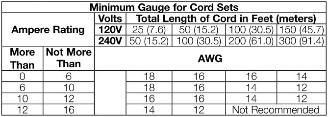
- USE PROPER EXTENSION CORD. Make sure your extension cord is in good condition. When using an extension cord, be sure to use one heavy enough to carry the current your product will draw. An undersized cord will cause a drop in line voltage resulting in overheating and loss of power. The following table shows the correct size to use depending on cord length and nameplate ampere rating. If in doubt, use the next heavier gauge. The smaller the gauge number, the heavier the cord. When operating a power tool outside, use an outdoor extension cord marked “W-A” or “W.” These cords are rated for outdoor use and reduce the risk of electric shock.
- WEAR PROPER APPAREL. Do not wear loose clothing, gloves, neckties, rings, bracelets, or other jewelry which may get caught in moving parts. Nonslip footwear is recommended. Wear protective hair covering to contain long hair. Air vents often cover moving parts and should also be avoided.
- ALWAYS USE SAFETY GLASSES. Also use face or dust mask if cutting operation is dusty. Everyday eyeglasses only have impact resistant lenses, they are not safety glasses.
- ACTUATING TOOL MAY RESULT IN FLYING DEBRIS, COLLATION MATERIAL, OR DUST WHICH COULD HARM OPERATOR’S EYES. The operator and all those persons in the general area should wear safety glasses with permanently attached side shields. Approved safety glasses are imprinted with the characters “Z87.1”. It is the employer’s responsibility to enforce the use of eye protection equipment by the tool operator and other people in the work area.
- SECURE WORK. Use of clamps or a vise to hold work when practical. It’s safer than using your hands and it frees both hands to operate tool.
- DON’T OVERREACH. Keep proper footing and balance at all times.
- MAINTAIN TOOLS WITH CARE. Keep tools sharp and clean for best and safest performance. Follow instructions for lubricating and changing accessories.
- DISCONNECT TOOLS before servicing; when changing accessories, such as blades, bits, cutters, and the like.
- REDUCE THE RISK OF UNINTENTIONAL STARTING. Make sure switch is in off position before plugging in.
- USE RECOMMENDED ACCESSORIES. Consult the instruction manual for recommended accessories. The use of improper accessories may cause risk of injury to persons.
- NEVER STAND ON TOOL. Serious injury could occur if the tool is tipped or if the cutting tool is unintentionally contacted.
- CHECK DAMAGED PARTS. Before further use of the tool, a guard or other part that is damaged should be carefully checked to determine that it will operate properly and perform its intended function—check for alignment of moving parts, binding of moving parts, breakage of parts, mounting, and any other conditions that may affect its operation. A guard or other part that is damaged should be properly repaired or replaced.
- DIRECTION OF FEED. Feed work into planer according to direction of feed arrows on top of the unit.
- NEVER LEAVE TOOL RUNNING UNATTENDED. TURN POWER OFF. Don’t leave tool until it comes to a complete stop.

Additional Specific Safety Rules for Planers
- To reduce the risk of injury, user must read and understand instruction manual before operating planer.
- Always wear eye protection and dust mask if necessary.
- Keep hands away from the underside of the cutter head carriage.
- Never clear clogs, make cutter knife replacement, or any other repairs/adjustments with unit plugged in.
- Make certain that the switch is in the OFF position before connecting plug to a power source.
- Be sure that the cutter knives are mounted as described in the instruction manual and check that all bolts are firmly tightened before connecting unit to power source.
- To avoid injury, never rotate the cutter block directly with your hands.
- Keep guards in place and in good working order.
- Stay alert—never operate the unit when tired or under the influence of drugs, alcohol, or medication.
- Do not use in dangerous environments. Do not use near flammable substances, in damp or wet locations, or expose to rain.
- Never plane material which is shorter than 12″ (304.8 mm).
- Exhaust chute: remove shavings with brush or vacuum after power has been shut off and cutter head has stopped rotating.
- ALWAYS LOCATE PLANER WITH PROPER CLEARANCE ON THE OUTFEED SIDE of the unit to prevent pinching or binding of the workpiece against any obstacle.
- Clean out your tool often, especially after heavy use. Dust and grit containing metal particles often accumulate on interior surfaces and could create a risk of serious injury, electric shock or electrocution. ALWAYS WEAR SAFETY GLASSES.
WARNING: For your own safety, it is recommended that two people carry this machine or serious injury could result.
WARNING: Always wear proper personal hearing protection that conforms to ANSI S12.6 (S3.19) during use. Under some conditions and duration of use, noise from this product may contribute to hearing loss.
WARNING: Some dust created by power sanding, sawing, grinding, drilling, and other construction activities contains chemicals known to the State of California to cause cancer, birth defects or other reproductive harm. Some examples of these chemicals are:
- lead from lead-based paints,
- crystalline silica from bricks and cement and other masonry products, and
- arsenic and chromium from chemically-treated lumber.
Your risk from these exposures varies, depending on how often you do this type of work. To reduce your exposure to these chemicals: work in a well ventilated area, and work with approved safety equipment, such as those dust masks that are specially designed to filter out microscopic particles.
- Avoid prolonged contact with dust from power sanding, sawing, grinding, drilling, and other construction activities. Wear protective clothing and wash exposed areas with soap and water. Allowing dust to get into your mouth, eyes, or lay on the skin may promote absorption of harmful chemicals.
WARNING: A dust mask or respirator should be worn by all persons entering the work area. The filter should be replaced daily or whenever the wearer has difficulty breathing. See your local hardware store for the proper NIOSH/OSHA approved dust mask.
- The label on your tool may include the following symbols. The symbols and their definitions are as follows:

Specifications
Input ______________ 120 V AC , 15 Amp
No load speed _______ 10,000 RPM
Feed speed __________ 14 ft. (4.3 m) per minute or 26 ft. (7,9 m) per minute
Planing height ________Maximum 6″ (152 mm), Minimum 1/8″ (3 mm)
Planing width ________ Maximum 13″ (325 mm)
Planing depth ________ Maximum 1/8″ (3 mm) (for boards 6″ (152 mm) wide or less)
Electrical Connection
Be sure your power supply agrees with the nameplate marking. Volts, 50/60 Hz or “AC only” means your planer must be operated only with alternating current and never with direct current. Voltage decrease of more than 10% will cause loss of power and overheating. All D E WALT tools are factory tested, if this tool does not operate, check the power supply.
Transporting the Planer (Fig. 1)
When moving your planer, carry it either by the side carrying handles (A) or by the handles at the base of the planer (B).

Bench Mounting
To facilitate bench mounting, two different sized holes (D) are provided on the four corners of your planer. If mounting the planer with bolts, use the larger holes. If mounting the planer with nails or screws, use the smaller holes. It is not necessary to use both sets of holes. Always mount your planer firmly to prevent movement. To enhance the tool’s portability, it can be mounted to a piece of 1/2″ (12.7 mm) or thicker plywood which can then be clamped to your work support or moved to other job sites and reclamped.
NOTE: If you elect to mount your planer onto a piece of plywood, make sure that the mounting screws don’t protrude from the bottom of the wood. The plywood must sit flush on the work support.
CAUTION: The mounting surface should not be warped or otherwise uneven.
ASSEMBLY
WARNING: Do not remove guards (E, Fig. 2). Serious injury could result.

WARNING: To reduce the risk of serious personal injury, turn tool off and disconnect tool from power source before making any adjustments or removing/installing attachments or accessories. An accidental start-up can cause injury.
TO ATTACH THE DEPTH ADJUSTMENT CRANK HANDLE (FIG. 3)
- Remove the screw located in the crank handle shaft.
- Insert the crank handle (F) over the shaft.
- Secure in place with the screw and T-wrench (G) provided.

DUST EJECTION PORTS
Your planer comes with a dust ejection port. The round port (I) as shown below is for use with a 4″ (100 mm) dust collector hose.
TO SET UP DUST EJECTION
- Select the port (I).
- Depress the lock button (K) on the chip ejection chute (H).
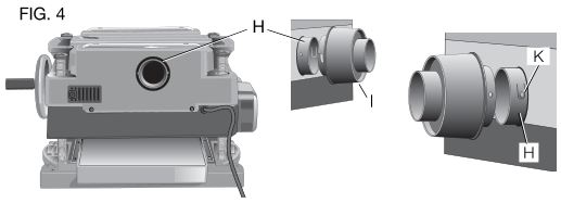
- Slide the notches in the dust port over the pins on the chip ejection chute.
- Rotate the port until the button engages the dust ejection chute and locks in place.

WARNING: Do not operate your planer without the dust ejection port locked into place. Do not insert anything into the dust ejection chute unless the planer is unplugged and you are clearing a clog or obstruction in the unit. Do not get your face or eyes near the dust ejection port when the planer is in operation. Serious injury could result.
WARNING: Chips are ejected at significant velocity. Keep hands and face clear of dust ejection port.
TO REMOVE THE DUST EJECTION PORT
- Use the T-wrench to depress the lock button (K) on the dust chute.
- Twist the port until the pins are disengaged from the notches on the port.
- Pull the dust ejection port off of the dust chute.
OPERATION
WARNING: To reduce the risk of serious personal injury, turn tool off and disconnect tool from power source before making any adjustments or removing/installing attachments or accessories. An accidental start-up can cause injury.
On/Off Switch
To turn the planer on, lift the switch (L) up. The planer locks on automatically. To turn the tool off, press the switch down. A hole (M) is provided under the switch for insertion of a padlock to lock off the planer.

Depth Adjustment
DEPTH ADJUSTMENT SCALE
The depth adjustment scale (N), located on the right front of your planer, indicates the finished thickness of your workpiece. One rotation of the depth adjustment crank is equal to 1/16″ (1.6 mm), half rotation is equal to 1/32″ (0.8 mm), etc.

DEPTH ADJUSTMENT CRANK
Turning the crank clockwise lowers the cutter head. Turning the crank counterclockwise raises the cutter head.
Material Removal Gauge
Your planer is equipped with a material removal gauge (O). It is used to indicate the amount of wood that will be removed in one pass with the carriage set at its current height.

TO USE THE MATERIAL REMOVAL GAUGE
- Slide approximately 3″ (75 mm) of your ma terial under the middle of the carriage.
- Be sure the wood is lying flat against the base of the planer. If the material is inserted at an angle, the reading may be inaccurate.
- Crank the carriage down on the ma terial until the material removal bar engages the wood. You will see the red arrow begin to move up the scale indicating the amount of material to be removed with the carriage at that height.
- Adjust the carriage height until the desired depth of cut appears on the gauge.
- Pull the material out from under the carriage.
- Turn the unit on and feed your material into the cutter head.
NOTE: Do not exceed the recommended depth of cut for various widths of material recommended on the material removal gauge.
WARNING: DO NOT switch the unit on with the material positioned under the carriage. Serious injury could result.
Speed Selection
NOTE: Only switch speeds when the planer is running.
Your planer has the ability to feed material at two different speeds. The two-speed feature (P) was designed to improve efficiency when planing and to provide the best possible surface finish to a variety of materials.
To remove material thickness more quickly, set the unit at speed “2”. This setting delivers 96 cuts per inch to the material.
For finishing, set the unit to speed “1”. Speed “1” is ideal for ensuring the finest finish on the last pass before your final thickness is achieved.
NOTE: When planing particularly hard or figured species of wood, speed “1” is recommended. The slower feed rate will reduce knife wear and tear-out by delivering 179 cuts per inch to the material.
Fan-Assisted Chip Ejection System
Your planer is equipped with a fan-assisted chip ejection system to aid in exhausting chips from the unit. The fan-assisted chip ejection system will work in conjunction with independent dust collection systems.
NOTE: It is not recommended that a shop vac be connected to the DW735. The capacity of most vacs does not support the volume of chips ejected during planing. The vacuum hose may clog stopping the flow of chips.
See the Troubleshooting Guide, for additional information.
Automatic Carriage Lock
There is no manual carriage lock on your planer. A device that automatically minimizes the movement that causes snipe during planing is designed into the four threaded posts.
Turret Stop
Your planer is equipped with a turret stop (Q) for repetitive planing at pre-set depths. Stops are set at 1/8″ (3 mm), 1/4″ (6.5 mm), 1/2″ (12.7 mm), 3/4″ (19 mm), 1″ (25.5 mm), and 1-1/4″ (32 mm).

TO SET THE MINIMUM DEPTH TO WHICH THE CARRIAGE CAN TRAVEL WITH THE TURRET STOP
- Be sure the carriage is set above 1-1/4″ (32 mm) before trying to set the turret stop.
- Turn the dial on the front left of the planer until the desired thickness setting aligns with the red indicator, then lower the carriage.
- Plane the workpiece at desired increments until the correct final thickness is achieved.
NOTE: Do not use force to crank the carriage below the level that the turret stop indicates. Permanent damage to the height adjustment system on your planer will result.
PLANING BASICS
Proper Planing Technique
TO PLANE YOUR MATERIAL
- Lower the carriage to the desired height for your first pass.
- Turn the unit on and feed the material into the feed rollers.
- Examine the finished cut and adjust the carriage to the appropriate height for your next pass.
NOTE: Flip the board back and forth between each pass as recommended in Proper Planing Techniques.
See the Troubleshooting Guide, for additional information.
WARNING: DO NOT turn the unit on with the material already inserted under the carriage. Wait until the rollers and cutter head are up to full speed before feeding your material into the machine.
For best results, plane both sides of the workpiece to reach a desired thickness. For example, if you need to remove 1/8″ (3 mm) from your workpiece, remove 1/16″ (1.6 mm) from each side. This not only allows the workpiece to dry with an even moisture content, it also produces finer cuts.
WARNING: Plane only wood that is free from foreign objects, with no loose knots and as few tight knots as possible. Do not plane wood that is severely warped, twisted, knotted or bowed.
WARNING: Do not place your body between the rear of the planer and a stationary object while material is feeding. Serious injury could result.
MINIMUM/MAXIMUM WIDTH/HEIGHT/DEPTH
NOTE: Always plane in the direction of the grain. Support the workpiece adequately at all times. Planing material less than 3/4″ (19 mm) wide is not recommended. If you must plane narrow material, group several pieces together and plane them as one wide workpiece whenever possible.
The maximum depth of cut your planer can take in one pass is 1/8″ (3 mm) [on material less than 6″ (152 mm) wide]. Never attempt to modify your planer to take a deeper cut. Follow the recommended depth/width of cut guidelines shown in Table A for best results.

Snipe
Snipe is a depression made when an unsupported end of your material drops toward the floor, causing the opposite end to lift up into the cutter head.
TO AVOID SNIPE
Feed the workpiece into the planer so it is level and remains flat against the base at all times.
Keep the workpiece level throughout planing operation by receiving or “catching” it from the rear of the planer.
If you are planing material that is especially long, the use of additional material support is recommended.
Twisted, Cupped and Bowed Wood

If both sides of your material are very rough or if the material is cupped, bowed or twisted, your planer may not produce the
desired result. Ideally, you should have at least one level face/surface on your material before you plane. Your thickness planer will work best with material that has been run through a jointer to produce one flat surface. If you do not have at least one flat surface or a jointer, see the following recommendations.
TO PLANE TWISTED WOOD (FIG. 11)

WARNING: Twisted wood may jam your thickness planer. If a jam occurs, turn the power off, disconnect the power supply and raise the carriage to release the material from the cutter head.
If your material is only slightly twisted:
Plane both sides alternating from one to the other until the desired thickness is reached.
TO PLANE CUPPED WOOD (FIG. 12)
To obtain the best possible results with cupped wood:

Rip the material down the middle and plane it as two separate pieces. Ripping the material reduces the severity of the cup and allows the machine to deliver better results. Understand that you will have to remove more material on cupped wood to achieve the desired thickness than you would on a normal board.
If ripping the material is not an option:
Plane one side of the material until flat, then plane the opposite side until it is also flat.
NOTE: Do not flip the board back and forth between each pass as recommended by the general planing directions.
TO PLANE BOWED WOOD (FIG. 13)
The feed rollers and cutter head in your planer will push the bow out of the material as it feeds. However, when the material exits the planer, the pressure of the rollers and cutter head will release allowing the wood to spring back into a bowed formation. To properly remove the bow, use a jointer.

Changing the Planer Knives
WARNING: To reduce the risk of serious personal injury, disconnect the planer from the power source before attempting to change or access the knives. An accidental start-up can cause injury.
TO CHANGE PLANER KNIVES (FIG. 14–19)
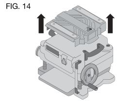
- Use the T-wrench to remove the four screws in the top of the planer.
- Lift the top off (Fig. 14) and place it aside.
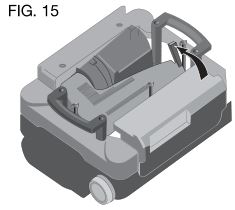
- Remove the three wing nuts that seal the dust shroud over the cutter head.
- Rotate the dust shroud up so the round connection that locks onto the fan housing is in the open position (Fig. 15).
- Push the dust shroud to the left so it disengages from the fan housing.
- Take the dust shroud out of the unit (Fig. 16) and set it aside.
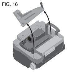
- The cutter head is now exposed.
If the eight screws in the cutter head clamp are not visible, use a piece of scrap wood to carefully rotate the cutter head (Fig. 17) until the screws are accessible and the cutter head lock lever (R) engages. This will prevent further rotation of the cutter head as you change the knives.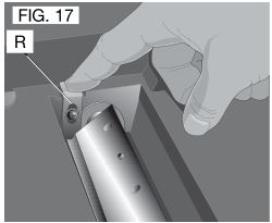

- Use the T-wrench to remove the eight screws on the knife clamp and set them in the small screws bin (S) on the front panel of the planer (Fig. 18).
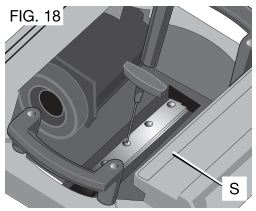
- Use the magnets on the top of the T-wrench to attract the knife clamp and lift it off of the cutter head. One of the knives should now be exposed.
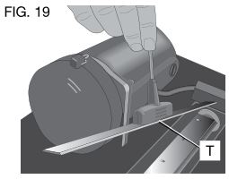
- Use the magnet (T) on the top of the T-wrench (Fig. 19) to attract the knife. Avoid touching it with your fingers.


If only one side of the knife is worn:
- Turn the knife around so that the sharp, unused edge hangs over the end of the cutter head where it will cut the material. Be sure to set the oblong holes in the knife over the pins machined on the cutter head.
- Reset the knife clamp over the knife. Be sure to align the beveled edge on the clamp with the sharp, cutting edge of the knife. If these are not aligned correctly, the clamp will not secure the knife properly.
- Install the screws into the clamp and tighten sufficiently.
To access the other two knives:
- Depress the cutter head lock lever (R) as shown in Figure 17.
- Use the piece of scrap wood to carefully turn the cutter head until it locks into place revealing another knife clamp.
- Follow the same knife change procedure indicated above.
- Repeat the procedure for the last dull knife.
After installing new knives:
- Insert the round end of the dust shroud into the fan housing and rotate it down to lock it into place.
- Place the three wing nuts back into the shroud.
- Screw the top cover of the planer back onto the unit.
NOTE: The planer will not operate if the top cover is not placed correctly.
MAINTENANCE
WARNING: To reduce the risk of serious personal injury, turn tool off and disconnect tool from power source before making any adjustments or removing/installing attachments or accessories. An accidental start-up can cause injury.
Brush Change (Fig. 20)
Your planer is equipped with brush caps (U) that are external to the motor. If your brushes need to be replaced, begin by acquiring a new set from a DEWALT service center or a dealer authorized to service DEWALT products. Use only identical DEWALT brushes.

TO REPLACE THE BRUSHES ON YOUR PLANER (FIG. 21)
- Use the T-wrench to remove the top cover and brush cover screen on the planer.
- Use a flathead screwdriver to unscrew the brush cap located in the right, rear of the unit (V).
- Do the same for the brush cap located on the side of the motor, inside the planer cover.
- Place the new brushes into the brush holders.
- After installing the brushes, replace the top cover and brush cover screen.
- Before using the planer, run the unit for 10 minutes to seat new brushes.
NOTE: If existing brushes do not need replacing, be sure to maintain the same orientation when you reinstall them.
Calibrating the Depth Adjustment Scale (Fig. 22)
The depth adjustment scale (N) on your planer is set at the factory. However, with extended use, the depth adjustment scale could show an incorrect measurement.

To check the depth adjustment scale, plane a piece of scrap wood, noting the measurement on the depth adjustment scale.
Measure the finished thickness of the workpiece. If the thickness of the workpiece does not match the reading on the depth adjustment scale, loosen the two screws (W) on the red indicator. Adjust the pointer up or down until its reading matches the finished thickness of the workpiece. Securely re-tighten the screws.
Base Maintenance
Keep the table clean and free from oil, grease, and pitch. Treat the table with paste wax to help maintain its smooth finish.
Circuit Breaker Reset Button (Fig. 23)

Your planer is equipped with an 18 amp circuit breaker. If your planer becomes overloaded and stops operating, turn off the planer, let the unit sit for 2 minutes and press the reset button (X) before you resume working.
WARNING: To prevent the planer from starting unexpectedly if power is interrupted by a circuit breaker trip, make sure the switch is in the OFF position before restoring power.
NOTE: Circuit breaker overload is often the result of dull knives. Change your knives on a regular basis to avoid tripping your breaker. Check your knives before re-setting the circuit breaker and continuing to plane.
See the Troubleshooting Guide for additional information on circuit breaker trips.
Replacing the Drive Belt
Drive belts are available at extra cost at D E WALT authorized service centers. Replacement of the drive belt should be performed by qualified service personnel.
Chip Ejection Fan (Fig. 24)

The chip ejection fan on your planer should be cleaned or cleared of debris periodically.
WARNING: Turn off and unplug the planer prior to accessing the chip ejection fan.
TO ACCESS THE FAN
- Remove the top cover of the planer with the T-wrench.
- Remove the dust shroud (Fig. 14–16) and place it aside.
- Remove the screws and clips around the fan housing.
- Remove the fan housing and place it aside as shown. The fan will now be exposed for cleaning.
See the Troubleshooting Guide for additional information.
WARNING: Be sure to properly attach the fan housing and assemble the shroud and top cover correctly before using your planer again.
Accessories
WARNING: Since accessories, other than those offered by DEWALT, have not been tested with this product, use of such accessories with this tool could be hazardous. To reduce the risk of injury, only DEWALT, recommended accessories should be used with this product.
Recommended accessories for use with your tool are available at extra cost from your distributor or local service center.
Four accessories are available for the DW735 Thickness Planer.
- DW7350 Mobile Stand
- DW7351 Folding Tables
- DW7352 13″ (325 mm) Knives
- DW7353 Chip Ejection Accessory
If you need any assistance in locating these accessories, please contact D E WALT Industrial Tool Co., 701 East Joppa Road, Baltimore, MD 21286 or call 1-800-4-D E WALT (1-800-433-9258) or www.dewalt.com
DW7351 Accessory Folding Tables (Fig. 25)
WARNING: For your own safety, read the tool instruction manual before attaching the tables. Failure to heed these warnings may result in personal injury and serious damage to the planer and the accessory. When servicing this tool, use only identical replacement parts. Have damaged cords replaced by an authorized service center.
Your DW7351 folding table box should include
2 folding tables
4 cap screws
4 springs
4 nuts
4 stepped bolts

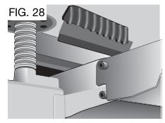
SET-UP AND INSTALLATION OF BASE HARDWARE (FIG. 26–28)
- Place planer on a secure table or workbench. Position planer so the front 3-4″ (75–100 mm) of the base can be accessed from the underside.
- Secure the rear of the planer to the table/bench with nails or screws to prevent it from tilting or falling from the table.
WARNING: The planer could tilt or fall from the table if it is not properly secured opposite the end where the folding table is being installed. Serious injury may result. - Place the spring onto the small end of the stepped bolt.
- Insert the end of the bolt with the spring around it into the larger hole on the side of the base.
- Push the stepped bolt all the way through the hole in the first rib on the underside of the planer. The spring should engage the rib slightly and the threads should show on the right side of the rib.
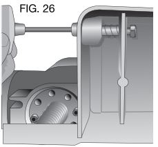
- On the underside of the planer, use a wrench to hold the nut in place while turning the stepped bolt into it. The T-wrench on your planer can be used to turn the stepped bolt until it is fully secured (Fig. 26).
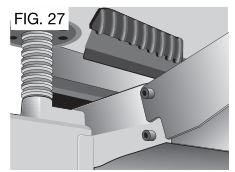
- Install the smaller screw into the lower threaded hole on the side of the base. Use the T-wrench to tighten that fastener securely (Fig. 27).

- Depress the top pin until it is flush with the base and slide the top hole of the table over the pin and release the pin so they lock together (Fig. 27, 28).
- To attach the table to the rear of the planer, install the bolts and spring following the above procedure.


Your tables should now fold up and down on the top screw and rest on the bottom screw while in position for planing.
NOTE: To transport the planer with the tables, fold them up and carry the unit as recommended by the planer manual.
WARNING: For your own safety, it is recommended that two people carry this machine or serious injury could result.
TO REMOVE THE TABLES
- Depress the spring-loaded bolts on the base and slide each end of the table toward you so they disengage the holes in the tables. You may want to use the T-wrench from your planer to push the bolts flush with the base to easily remove the tables.
- Leave the hardware (stepped bolts and small cap screw) in the base until you need to re-attach the tables.
Repairs
To assure product SAFETY and RELIABILITY, repairs, maintenance and adjustment should be performed by authorized service centers or other qualified service personnel. Always use identical replacement parts.
Register Online
Thank you for your purchase. Register your product now for:
- WARRANTY SERVICE: Registering your product will help you obtain more efficient warranty service in case there is a problem with your product.
- CONFIRMATION OF OWNERSHIP: In case of an insurance loss, such as fire, flood or theft, your registration of ownership will serve as your proof of purchase.
- FOR YOUR SAFETY: Registering your product will allow us to contact you in the unlikely event a safety notification is required under the Federal Consumer Safety Act.
Register online at www.dewalt.com/register.
Three Year Limited Warranty
DEWALT will repair, without charge, any defects due to faulty materials or workmanship for three years from the date of purchase. This warranty does not cover part failure due to normal wear or tool abuse. For further detail of warranty coverage and warranty repair information, visit www.dewalt.com or call 1-800-4-D E WALT (1-800-433-9258). This warranty does not apply to accessories or damage caused where repairs have been made or attempted by others. This warranty gives you specific legal rights and you may have other rights which vary in certain states or provinces.
In addition to the warranty, DEWALT tools are covered by our:
1 YEAR FREE SERVICE
DEWALT will maintain the tool and replace worn parts caused by normal use, for free, any time during the first year after purchase.
90 DAY MONEY BACK GUARANTEE
If you are not completely satisfied with the performance of your DEWALT Power Tool, Laser, or Nailer for any reason, you can return it within 90 days from the date of purchase with a receipt for a full refund – no questions asked.
LATIN AMERICA: This warranty does not apply to products sold in Latin America. For products sold in Latin America, see country specific warranty information contained in the packaging, call the local company or see website for warranty information.
FREE WARNING LABEL REPLACEMENT: If your warning labels become illegible or are missing, call 1-800-4-D E WALT (1-800-433-9258) for a free replacement.

TROUBLESHOOTING GUIDE
IF THE UNIT DOES NOT RUN, CHECK TO SEE:
• if the unit is plugged in.
• if the dust shroud is properly in place.
• if the top cover is properly in place.
• if the circuit breaker needs to be reset.
IF THE MATERIAL DOES NOT FEED PROPERLY, CHECK FOR:
• dull knives.
• excess clogging in the dust shroud.
• excess oil/debris from feed rollers.
• excessively twisted, cupped or bowed material.
• a broken drive belt.
IF CHIPS DO NOT EJECT FROM THE REAR OF THE UNIT, CHECK TO SEE:
• if the dust shroud is properly in place.
• if the dust shroud and fan are clogged or obstructed.
IF THE CIRCUIT BREAKER TRIPS:
• check for dull knives. Dull knives could cause motor overloading.
• reduce depth of cut. An overly aggressive cut could cause motor overloading.
• drop feed rate to 14 ft/min. A reduction in feed rate will reduce the load on the motor and prevent breaker trips.
IF THE BRANCH (HOUSE/SHOP) CIRCUIT BREAKER TRIPS REPEATEDLY:
• unplug or turn off other devices sharing the circuit with the planer OR use the planer on another branch circuit by itself.
• check for dull knives. Dull knives could cause motor overloading.
• reduce depth of cut. An overly aggressive cut could cause motor overloading.
• drop feed rate to 14 ft/min. A reduction in feed rate will reduce the load on the motor and prevent breaker trips.
NOTE: Even under normal loading conditions, other electrical loads on the same branch circuit may cause the circuit breaker to trip.
DOWNLOAD SOURCES
- DEWALT DW735 Portable Thickness Planer Instruction Manual – Download [optimized]
- DEWALT DW735 Portable Thickness Planer Instruction Manual – Download
FAQ’S
How can I tell if my planer is a DW735 or a DW733?
The DW735 has a 3/4″ wide by 2-1/4″ long logo on the front of the planer. The DW733 does not have this logo.
Is the DW735 compatible with the DW733 outfeed table?
No, the DW735 outfeed table is not compatible with the DW733.
What is the maximum depth of cut for this planer?
The maximum depth of cut for this planer is 1/8″.
What is the maximum width of material that can be planed?
The maximum width of material that can be planed with this tool is 13″.
What is the capacity of this thickness planer?
This thickness planer has a capacity of up to 20″ wide by 1-3/8″ thick. It will plane up to a 3/4″ thick board if you use it with an outfeed support stand.
Can I use an outfeed support stand with this tool?
Yes, you can use an outfeed support stand with this tool. However, it will only plane boards up to 3/4″ thick. If you want to plane boards thicker than 3/4″, you will need to purchase an additional infeed and outfeed support stand (DWA1255). These stands are sold separately from the tool and are not included in the box. You can also purchase them from your local hardware store or online retailer. To order these stands, go to www.dewalt.com/planers-jointer-support-stands and enter your zip code into the “Find a Store” field at the bottom right corner of the page. Then click “Find Stores.” If your local hardware store or online retailer does not carry them, they can be ordered directly from us at 1-800-433-9258 (Monday – Friday 8 a.m.-5 p.m., EST). Please have your planer’s model number available when ordering these stands so we can ensure that you receive the correct stands for your tool.
Does the Dewalt DW735 come with blades?
Your DeWALT DW735 comes with them already installed and then when it’s time to replace them… surprise! You have one more use because they’re reversible. But when it’s time to replace them, you can pick up a double pack (6 blades) of the DeWALT 13″ Planer knives for under $80.
Can you run painted wood through a planer?
It is okay to plane most types of painted wood but the blades may dull faster. For safety and environmental reasons, planing painted wood with lead based or cementitious (waterproofing) paint is NOT RECOMMENDED.
Can you sand out planer snipe?
If it’s really small and light, you might get away with a little sanding on the ends, or you can run it through the planer again at a smaller thickness.
Does a planer have to be level?
If the surface isn’t flat you’ll end up getting snipe when your board runs off that bump. The cutter head will be removing material relative to the bed, so any defects in the bed will certainly translate into how the cutter meets the board.
Does a planer make wood smooth?
If neither face is true, a jointer/planer can be used to smooth one face, then the other side can be planed parallel to the first on the thickness planer.) The freestanding planer is a near relation of the jointer/planer. It, too, cuts with a cutter head, but the planer smooths the face of much wider stock.
How do you prevent tears from a planer?
To best prevent this, you need two things. First, use a plane with an adjustable mouth, so you can close it down close to the blade [Photo below] to limit the thickness of the shavings you’ll make. Second, you want a steeper cutting angle of 50–55°.
VIDEO
DEWALT DW735 Portable Thickness Planer
www://dewalt.com/