USE AND CARE GUIDE
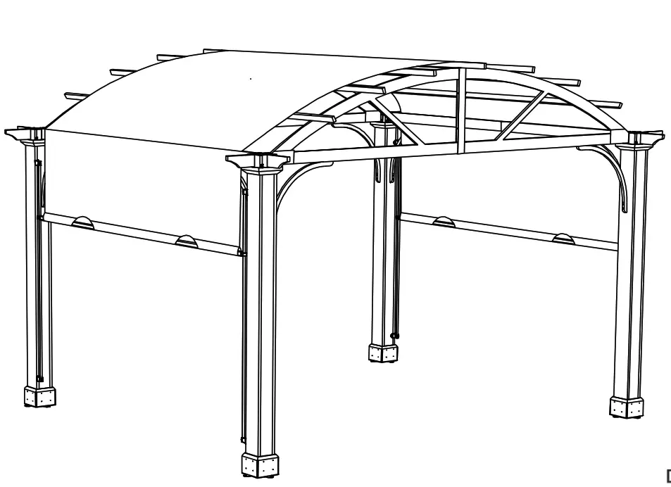
10X12 LONGFORD PERGOLA
Item# 1004 662 155/1004 649 550/1004 649 549/ 1004 547 739
Model #A106003600
Questions, problems, missing parts? Before returning to the store,
call Hampton Bay Customer Service
8 a.m. – 7 p.m., EST, Monday-Friday, 9 a.m. – 6 p.m., EST, Saturday
1-855-HD-HAMPTON
HAMPTONBAY.COM
THANK YOU
We appreciate the trust and confidence you have placed in Hampton Bay through the purchase of this Pergola. We strive to continually create quality products designed to enhance your home. Visit us online to see our full line of products available for your home improvement needs. Thank you for choosing Hampton Bay!
Safety Information
- At least 2 persons are required for this assembly.
- Some parts may contain sharp edges. Wear protective gloves.
- When assembling and using this product, basic safety precautions should always be followed to reduce the risk of personal injury and damage to equipment. Please read all instructions before assembly and usage.
NOTICE: For outdoor use only.
 WARNING: Keep all flame and heat sources away from this pergola fabric. This pergola is made with fabric that meets CPAI-84 specifications for flame resistance. It is not fireproof. The fabric will burn if left in continuous contact with any flame source. The application of any foreign substance to the pergola fabric may render the flame-resistant properties ineffective.
![]() CAUTION: Do not climb on top of the pergola. Falling off the pergola can result in serious injury, possibly even death.
CAUTION: Do not climb on top of the pergola. Falling off the pergola can result in serious injury, possibly even death.
![]() DANGER: This unit is heavy! Do not assemble this item alone.
DANGER: This unit is heavy! Do not assemble this item alone.
WARNING: While this pergola is manufactured to withstand winds through only the supplied ground stakes, in areas subject to frequent severe weather, securing the pergola to a deck, concrete patio or footings should be considered. Snow must be cleared off regularly during snowy days. Remove the snow at the top when it is thicker than 4 inches. In order to avoid damage, use a plastic snow rake to remove excess snow and ice buildup from the roof and keep away from falling debris.
Warranty’
2 YEAR WARRANTY
WHAT IS COVERED
This limited warranty is extended to the original purchaser and applies to defects in materials and workmanship of your item provided the item is maintained with care and used only for personal, residential purposes. The item is warranted to be free from defects in material or workmanship for a period of 2 years.
WHAT IS NOT COVERED
We do not reimburse for transportation of delivery costs or compensate the individual or any outside party for assembling or disassembling the product. Contact the Customer Service Team at 1-855-HD-HAMPTON or visit HAMPTONBAY.COM.
Production Number: 2020BPCN10
Pre-Assembly
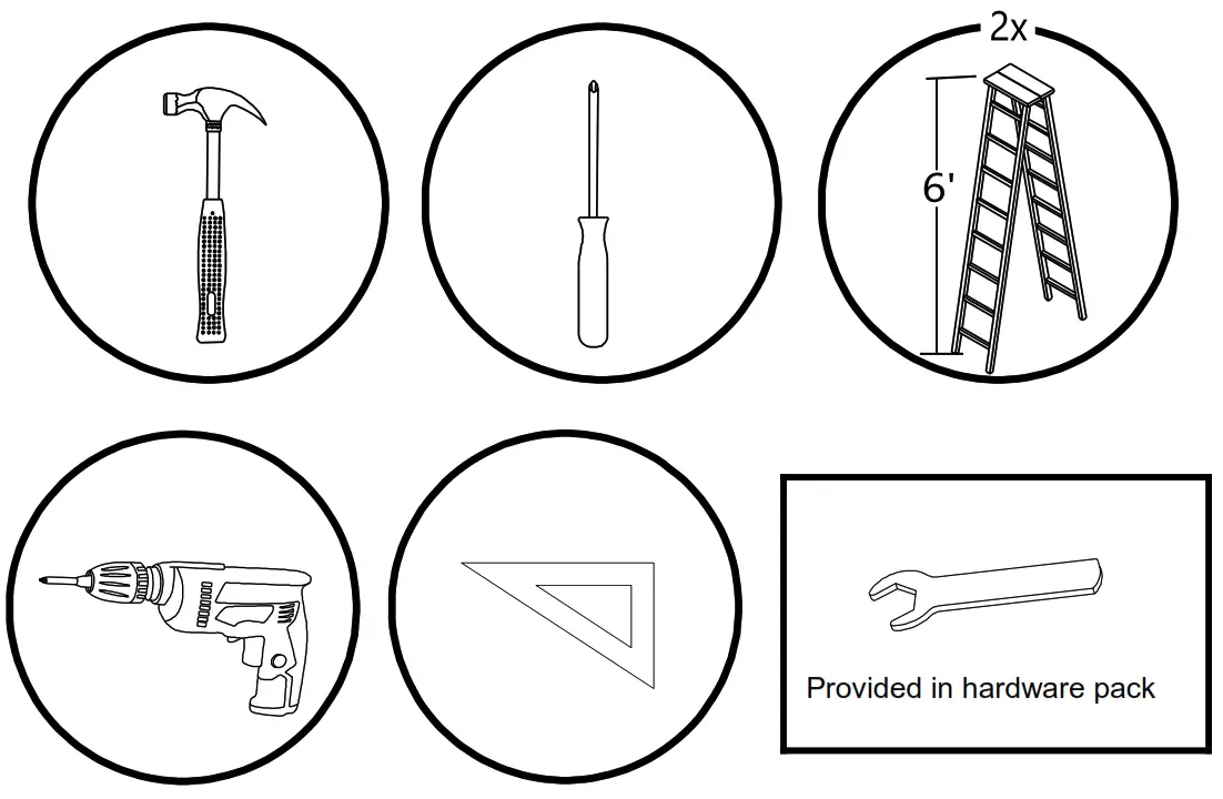
IMPORTANT
Requires at least 2 persons for the installation work. Approximate installation time:2~3 hours.

PLANNING ASSEMBLY
Before beginning the assembly of this product, make sure all parts are present. Compare parts with the Hardware Included and Package Contents lists. If any part is missing or damaged, do not attempt to assemble the product. Contact customer service for replacement parts.
HARDWARE INCLUDED
![]() NOTE: Hardware not shown to actual size.
NOTE: Hardware not shown to actual size.
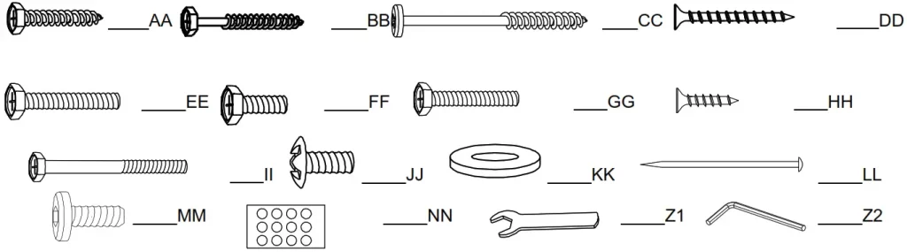
| Part | Part Number | Description | Quantity | Additional Hardware |
| AA | H36035C31 | M6 X 35 Screw | 40 | 2 |
| BB | H36060C31 | M6 X 60 Screw | 16 | 1 |
| CC | H40080C31 | M6 X 80 Screw | 8 | 1 |
| DD | H11040B31 | M5 X40 Screw | 64 | 4 |
| EE | H02045C11 | M6 X 45 Bolt | 16 | 1 |
| FF | H02020C11 | M6 X 20 Bolt | 8 | 1 |
| GG | H02040C11 | M6 X 40 Bolt | 4 | 1 |
| HH | H11025B11 | M5 X 25 Screw | 40 | 2 |
| II | H02055C11 | M6 X 55 Bolt | 14 | 1 |
| JJ | H09012C11 | M6 X 12 Bolt | 4 | 1 |
| KK | H19001C11 | M6 Flat Washer | 138 | 7 |
| LL | P12401A01001 | ¢8*180 Stake | 8 | 0 |
| MM | H06015C11 | M6 X 15 Bolt | 36 | 2 |
| NN | P15601A27000 | Sticker | 1 | 0 |
| Z1 | H00001C12 | M6 Wrench | 2 | 0 |
| Z2 | H00002C12 | M6 Allen key | 1 | 0 |
PACKAGE CONTENTS
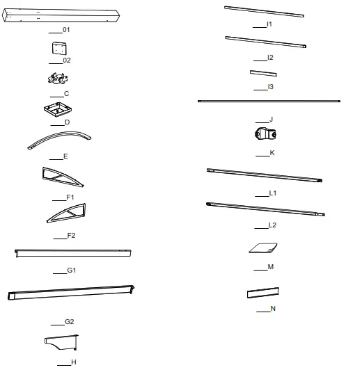
| Part | Part Number | Description | Quantity |
| 1 | P000200217 | Post | 4 |
| 2 | P006100082 | Base Cover | 16 |
| C | P000100135 | Base | 4 |
| D | P000300031 | Cover | 4 |
| E | P005000197 | Arc Support | 8 |
| F1 | P000400490 | Right Curved Frame | 2 |
| F2 | P000400491 | Left Curved Frame | 2 |
| G1 | P000400488 | Right Beam | 2 |
| G2 | P000400489 | Left Beam | 2 |
| H | P005600116 | Decorative Profile | 8 |
| I1 | P000600665 | Right Cross Beam | 7 |
| I2 | P000600666 | Left Cross Beam | 7 |
| I3 | P000500563 | Cross Beam Connector | 7 |
| J | P005700187 | Guide Tube | 4 |
| K | P005700564 | Guide Tube Connector | 8 |
| L1 | P005700188 | Canopy Tube 1 | 2 |
| L2 | P005700189 | Canopy Tube 2 | 2 |
| M | P001100279 | Canopy | 1 |
| N | P000500562 | Connector | 4 |
Attaching the Base
Attach the Base (C) to the Post (01) using screws (HH). It is suggested to pre-drill holes for easier installation of the base.
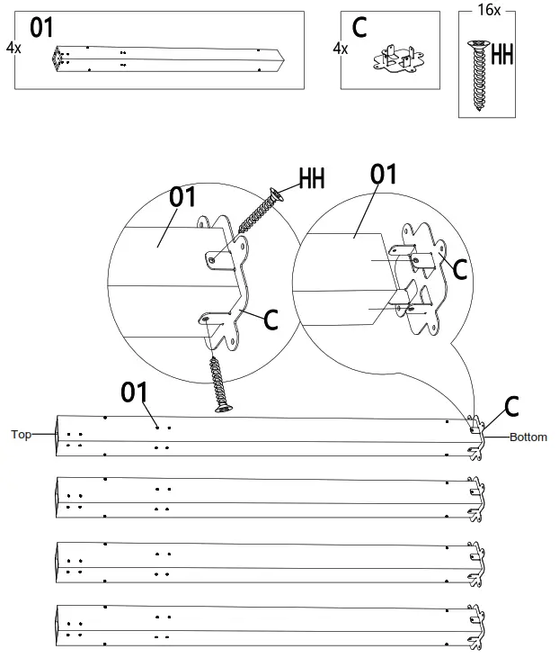
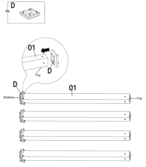
Insert the Cover (D) into the top of the Post (01), but don’t assemble.
![]() NOTE: To avoid destroying the finish, do not put the parts on the ground directly.
NOTE: To avoid destroying the finish, do not put the parts on the ground directly.
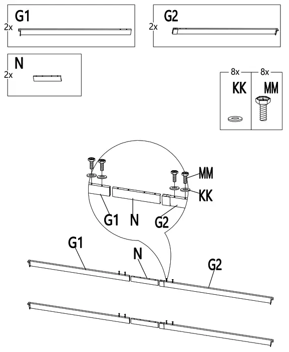
Connecting the Beams and Connector
Connect the Beams (G1&G2) with the Connector (N) using bolts (MM) and flat washers (KK).
![]() NOTE: To avoid destroying the finish, do not put the parts on the ground
NOTE: To avoid destroying the finish, do not put the parts on the ground
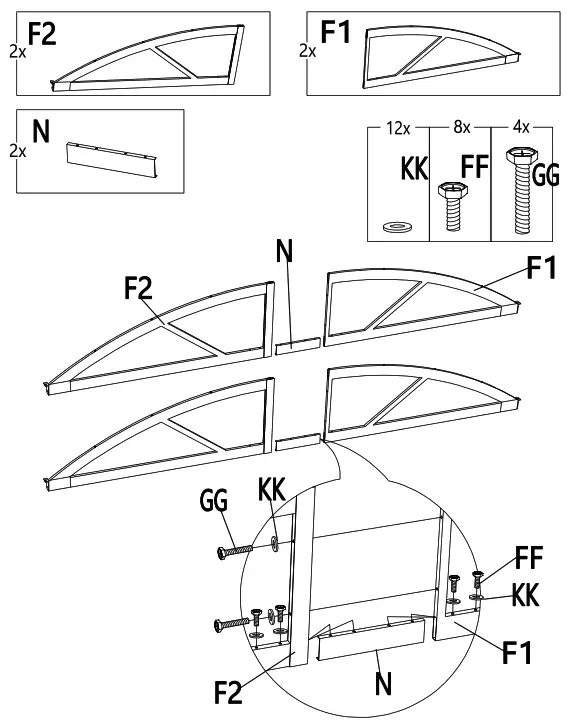
Connecting the Curved Frames and Connector
![]() NOTE: To avoid destroying the finish, do not put the parts on the ground directly.
NOTE: To avoid destroying the finish, do not put the parts on the ground directly.
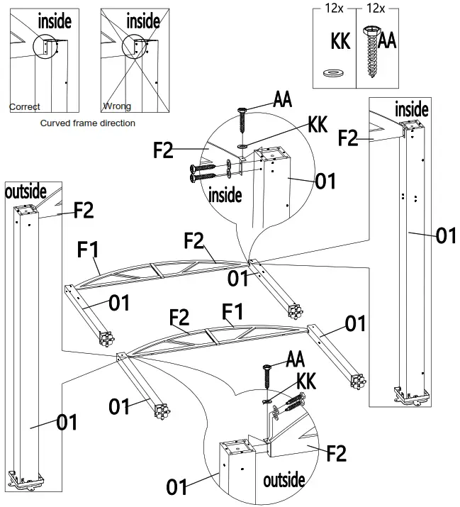
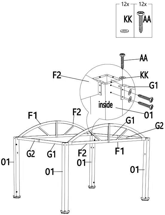
Connecting the Curved Frames and Posts
Attach the Curved frames (F1&F2) with the Post (01) using screws (AA) and flat washers (KK).
![]() NOTE: Pay close attention to the hole placement to ensure proper assembly. Also, pay attention to the direction of the curved frames.
NOTE: Pay close attention to the hole placement to ensure proper assembly. Also, pay attention to the direction of the curved frames.
Attaching the Beams
Attach the beams (G1&G2) to the post (01) using screws (AA) and flat washers (KK).
![]() NOTE: Ensure post is oriented properly before installing beams, inside of posts must have holes for canopy guide tube.
NOTE: Ensure post is oriented properly before installing beams, inside of posts must have holes for canopy guide tube.
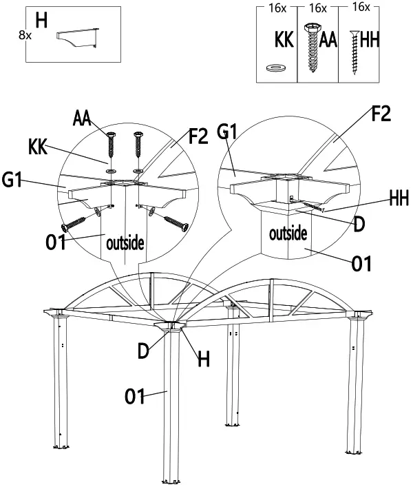
Attaching the Decorative Profile
Attach the decorative profiles (H) to the post (01) using screw (AA) and washer (KK). Attach the Cover (D) to the post (01) using screw (HH).
It is recommended to predrill holes to install the Cover (D).
![]() NOTE: To avoid destroying the finish, do not put the parts on the ground directly.
NOTE: To avoid destroying the finish, do not put the parts on the ground directly.
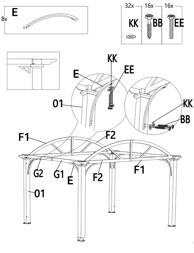
Attaching the Arc Support
Attach the arc support (E) to the curved frames (F1&F2), beams (G1&G2) and post (01) using bolts (EE), screws (BB) and flat washers (KK).
![]() NOTE: To avoid destroying the finish, do not put the parts on the ground directly. Make sure the angle between the curved frame and post is 90°when attaching the Support, the triangular rule can be used if necessary.
NOTE: To avoid destroying the finish, do not put the parts on the ground directly. Make sure the angle between the curved frame and post is 90°when attaching the Support, the triangular rule can be used if necessary.
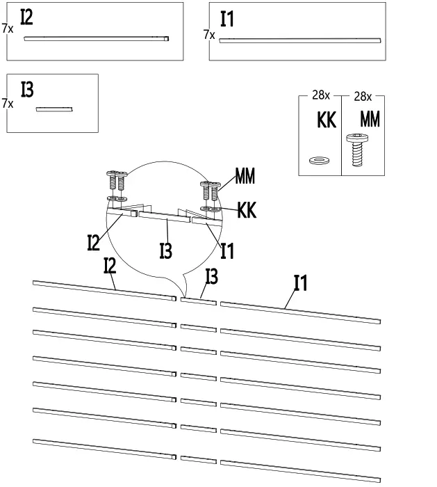
Connecting the Crossbeam
Connect the cross beam (I1&I2) with cross beam connector (I3) using bolts (MM) and flat washers (KK)
![]() NOTE: To avoid destroying the finish, do not put the parts on the ground directly.
NOTE: To avoid destroying the finish, do not put the parts on the ground directly.
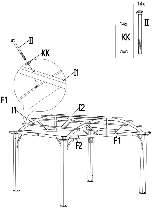
Attaching the Cross Beams
Attach the cross beams (I1&I2) and curved frames (F1&F2) using bolts (II) and flat washers (KK).
![]() NOTE: To avoid destroying the finish, do not put the parts on the ground directly.
NOTE: To avoid destroying the finish, do not put the parts on the ground directly.
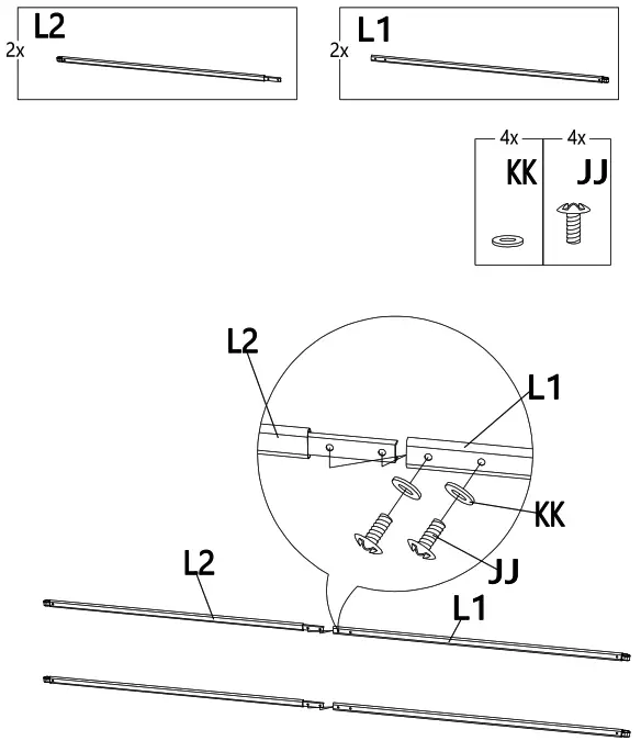
Connecting the Canopy Tube
Connect the canopy tube 1 (L1) with the canopy tube 2 (L2) using bolt (JJ) and flat washer (KK).
![]() NOTE: To avoid destroying the finish, do not put the parts on the ground directly.
NOTE: To avoid destroying the finish, do not put the parts on the ground directly.
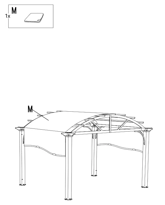
Cover the canopy (M) on the pergola.
![]() NOTE: To avoid destroying the finish, do not put the parts on the ground directly.
NOTE: To avoid destroying the finish, do not put the parts on the ground directly.
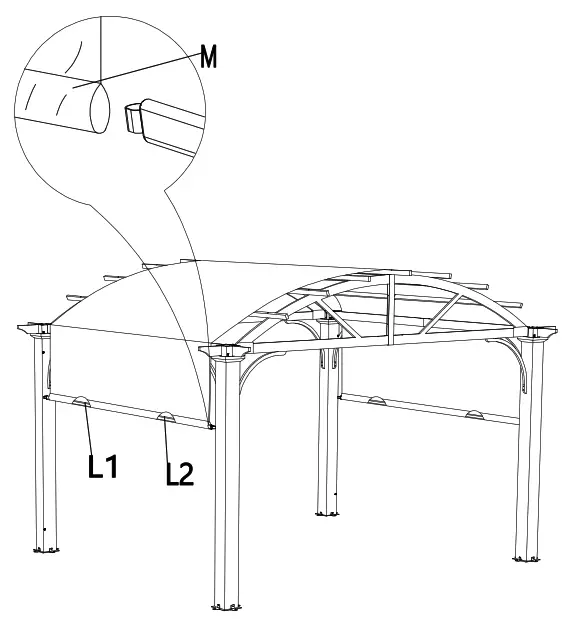
Inserting the Canopy Tube
Insert the canopy tubes (L1&L2) into the canopy (M).
![]() NOTE: To avoid destroying the finish, do not put the parts on the go directly.
NOTE: To avoid destroying the finish, do not put the parts on the go directly.
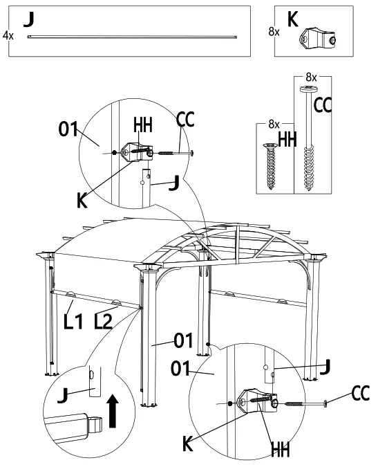
Inserting the Guide Tube
Insert the Guide tube (J) into the Canopy tubes (L1&L2). Then connect the Guide tube (J) and Guide tube connector (K) with Post (01) using screws (CC). Then secure the guide tube connect (K) to the post (01) using a screw (HH). For easier installation, it is recommended to predrill holes for screw bolt (HH) to make the Guide tube connector (K) level.
NOTE: To avoid destroying the finish, do not put the parts on the ground directly. You may need to slide the canopy back and forth a few times to ensure it is square.
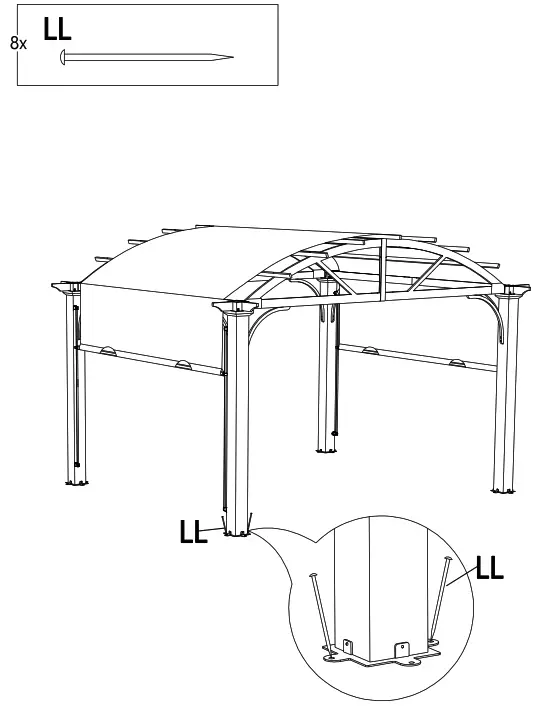
Securing the pergola
Secure the pergola on the ground with stakes (LL)
It is recommended for anchoring on wood or concrete surface for more stability using setscrew (Purchased separately).
![]() NOTE: To avoid destroying the finish, do not put the parts on the ground directly.
NOTE: To avoid destroying the finish, do not put the parts on the ground directly.
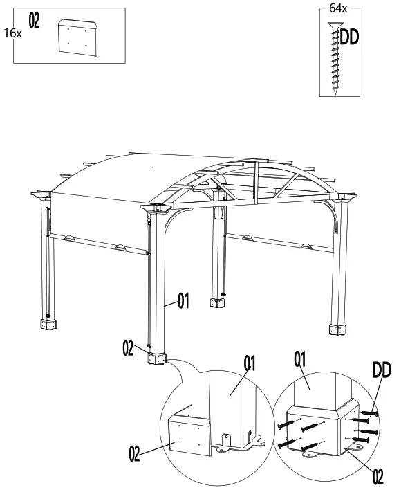
Attach the base cover (02) and post (01) using screws (DD).
![]() NOTE: To avoid destroying the finish, do not put the parts on the ground directly.
NOTE: To avoid destroying the finish, do not put the parts on the ground directly.
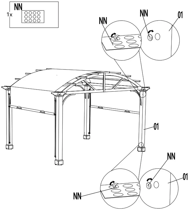
Apply the stickers on the pre-drill holes
Apply the stickers (NN) to cover the pre-drill holes on the Posts (01) if you choose, but not required.
![]() NOTE: To avoid destroying the finish, do not put the parts on the ground directly.
NOTE: To avoid destroying the finish, do not put the parts on the ground directly.
Care and Cleaning
- Steel components for this gazebo are treated with rust-inhibiting paint that protects it from rusting. However, due to the nature of steel, surface oxidation (rusting) will occur if these protective coatings are scratched. This is not a defect and thus not covered by the warranty. To minimize this condition, it is recommended to use care when assembling and handling the product to prevent scratching the paint. Should any scratching or damage occur, it is recommended to cover the scratch immediately with rust-inhibiting paint (not included). Surface rust can also be easily removed with a very light application of regular cooking oil. If surface oxidation (rusting) occurs and if no measure is taken to prevent this, the oxidation may start dripping onto the deck or patio and caused damaging stains, which may be difficult to remove. This can be prevented if the above-mentioned measures are taken to keep the product from oxidizing.
- Do not use bleach, acid, or other abrasive cleaners on the roof or frame parts.
- Keep instruction manual for future reference.
- Keep the original packaging to store the gazebo.
- Remove canopy during bad weather and windy conditions.
- When not in use, store in a cool, dry area.
Questions, problems, missing parts? Before returning to the store, call Hampton Bay Customer Service
8 a.m. – 7 p.m., EST, Monday-Friday, 9 a.m. – 6 p.m., EST, Saturday
1-855-HD-HAMPTON
HAMPTONBAY.COM
Retain this manual for future use.