Safety Information
READ AND SAVE THESE INSTRUCTIONS.
- To reduce the risk of electric shock, ensure the electricity has been turned off at the circuit breaker or fuse box before you begin.
- All wiring must be in accordance with the National Electrical Code ANSI/NFPA 70 and local electrical codes. Electrical installation should be performed by a qualified licensed electrician.
- The outlet box and support structure must be securely mounted and capable of reliably supporting a minimum of 35 lbs. (15.9 kg). Use only UL-listed outlet boxes marked “Acceptable for Fan Support of 35 lbs. (15.9 kg) or less.”
- The fan must be mounted with a minimum of 7 ft (2.1 m) of clearance from the trailing edge of the blades to the floor.
- Do not place objects in the path of the blades.
- To avoid personal injury or damage to the fan and other items, use caution when working around or cleaning the fan.
- After making electrical connections, spliced conductors should be turned upward and pushed carefully up into the outlet box. The wires should be spread apart with the grounded conductor and the equipment-grounding conductor on one side of the outlet box.
- All set screws must be checked and retightened where necessary before installation.
Pre-Installation
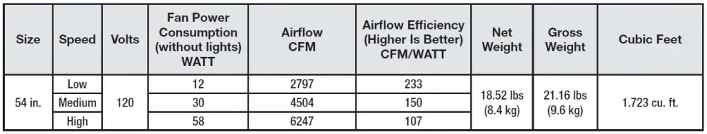
SPECIFICATIONS
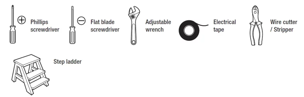
TOOLS REQUIRED
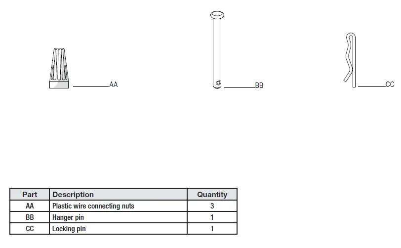
Pre-Installation (continued) HARDWARE INCLUDED
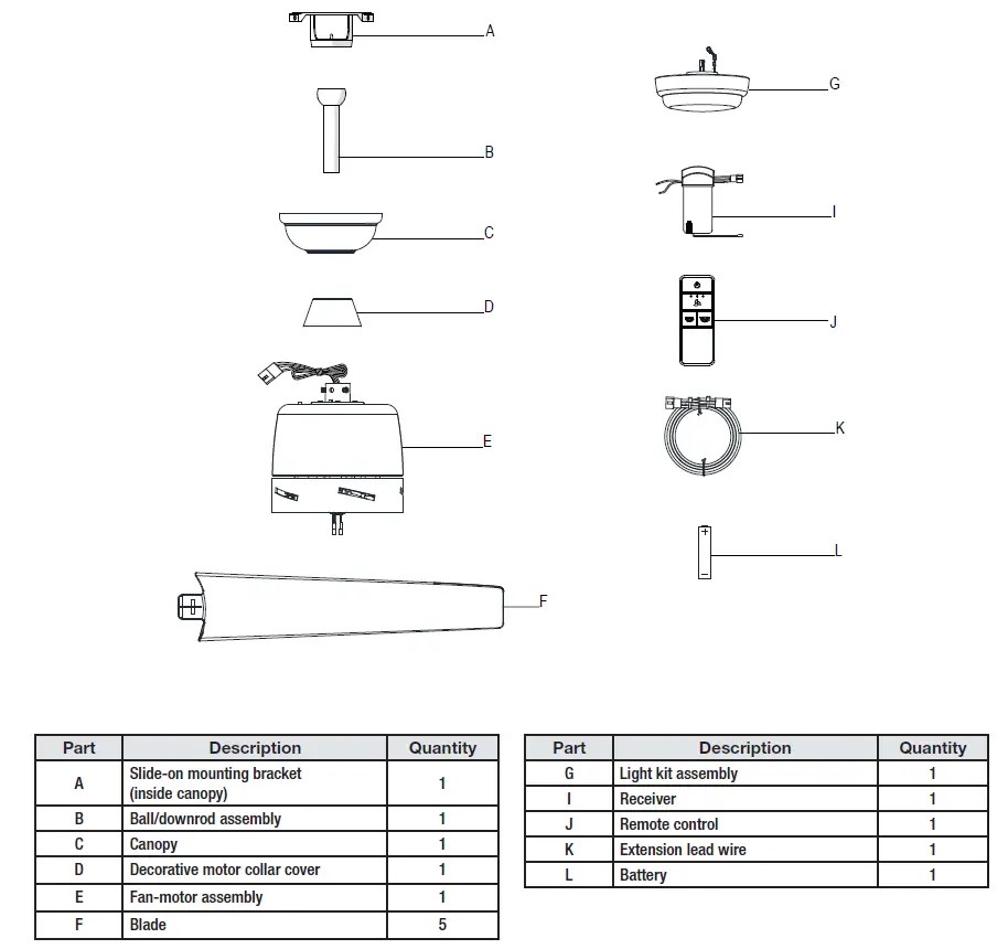
Pre-Installation (continued) PACKAGE CONTENTS
MOUNTING OPTIONS
WARNING: To reduce the risk of fire, electric shock or personal injury, mount to outlet box marked “Acceptable for fan support of 35 lbs. (15.9 kg) or less”, and use screws provided with the outlet box. An outlet box commonly used for the support of lighting fixtures may not be acceptable for fan support and may need to be replaced. If in doubt, consult a qualified electrician.
If your ceiling fan does not have an existing UL-listed mounting box, then install one using the following instructions:
- Disconnect the power by removing the fuses or turning off the circuit breakers.
- Secure the outlet box directly to the building structure. Use the appropriate fasteners and materials. The outlet box and support structure must be securely mounted and capable of reliably supporting a minimum of 35 lbs. (15.9 kg). Use only UL-listed outlet boxes marked “Acceptable for fan support of 35 lbs. (15.9 kg) or less” Do not use a plastic outlet box.
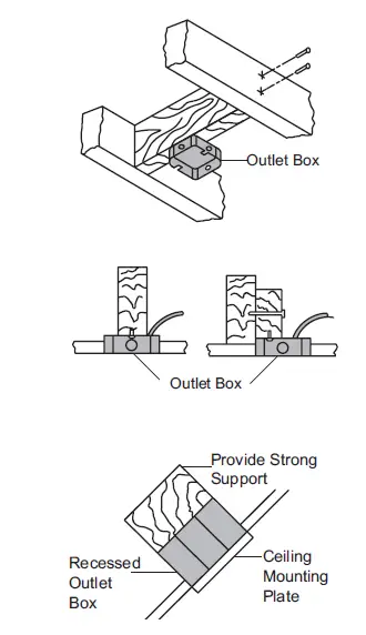
If the canopy touches the download, then remove the decorative canopy bottom cover, and turn the canopy 180° before attaching the canopy to the mounting plate. To hang your fan where there is an existing fixture but no ceiling joist, you may need an installation hanger bar as shown above (available at any Home Depot store).
Assembly – Standard Ceiling Mount
Preparing for mounting
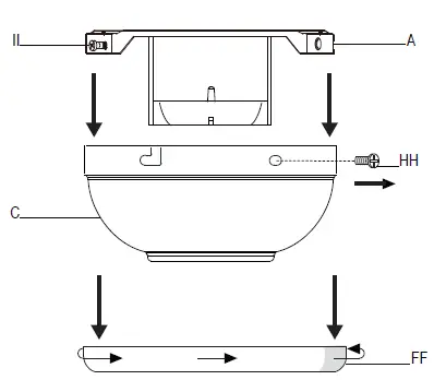
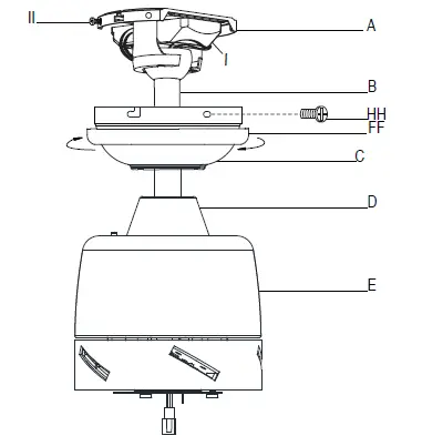
- Remove the canopy ring (FF) from the canopy (C) by turning the ring counterclockwise until it unlocks.
- Remove the mounting bracket (A) from the canopy (C) by loosening the two canopy screws (II) located in the “L-shaped” slots.
- Remove and save the two canopy screws (HH) in the round holes. This will enable you to remove the mounting bracket (A).
Routing the wires
- Route the wires exiting the top of the fan motor assembly (E) through the center of the canopy ring (FF). Make sure the slots on the canopy ring (FF) are on top.
- Insert the balldownrod (B) through the canopy (C) and slide the decorative motor collar cover (D) onto the end of the ball/downrod (B). Make sure the slots on the canopy (C) are on top.
- Route the wires exiting the top of the fan motor assembly (E) through the downrod (B) as shown.
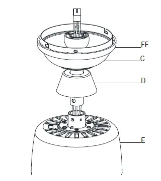
Assembling the fan
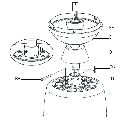
- Loosen, but do not remove, the setscrews (JJ) on the collar on top of the fan-motor assembly (E).
- Align the holes at the bottom of the ball/downrod assembly (B) with the holes in the collar on top of the fan-motor assembly (E).
- Carefully insert the hanger pin (BB)through the holes in the collar and ball/downrod assemblyB. Be careful not to jam the hanger pin (BB) against the wiring inside the ball/ downrod assembly (B).
- Insert the locking pin (CC) through the hole near the end of the hanger pin (BB) until it snaps into its locked position.
- Re-tighten the setscrews (JJ) on the collar on top of the fan-motor assembly (E).
Assembly – Hanging the Fan
Attaching the fan to the electrical box
- Loosen the two mounting screws (TT) in the outlet box.
- Pass the 120-Volt supply wires through the center hole in the mounting bracket (A).
- Slide the mounting bracket (A) on to the mounting screws (TT) and center the mounting bracket (A) in relation to the outlet box. If necessary, use leveling washers (not included) between the slide-on mounting bracket (A) and the outlet box. The flat side of the slide-on mounting bracket (A) should face toward the outlet box, as shown.
- Securely tighten the two mounting screws (TT).
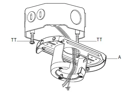
Hanging the fan
- Carefully lift the fan-motor assembly (E) up to the slide-on mounting bracket (A).
- Insert the ball portion of the ball/downrod assembly into the socket of the slide-on mounting bracket (A).
- Turn the ball/downrod (B) assembly clockwise until it is seated with the tab of the slide-on mounting bracket (A) aligned with the slot in the ball.
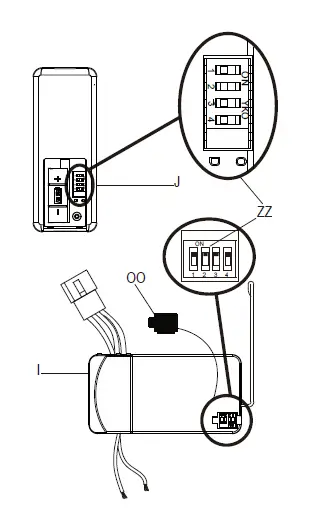
Setting the code on the remote control and receiver
- Remove the remote control (J) battery cover by pressing firmly on the arrow and sliding the cover off.
- Slide the dip switches (ZZ) to your choice of either up or down. The factory setting is up.
- Slide the dip switches (ZZ) on the receiver (I) to the same position as set on the remote control (J).
- Install the A23 12V battery (L).
- Replace the battery cover on the remote control (J).
- Insert the silicone rubber stopper (OO) into the hole on the receiver (I) to cover the dip switches.
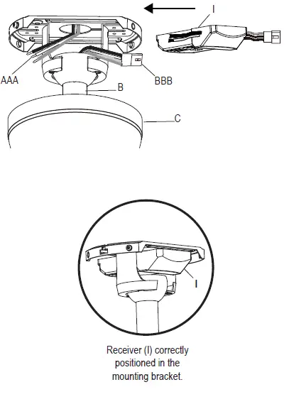
Installing the receiver
- Position the house supply wires (AAA) to one side of the slide-on mounting bracket (A); position the fan wires (BBB) to the opposite side.
- Insert the narrow end of the receiver (I) (as shown, flat side towards the ceiling) into the slide-on mounting bracket until it rests on top of the ball/downrod assembly.
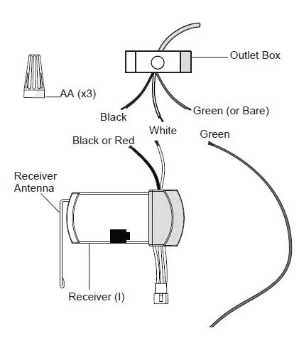
Wiring the receiver to the household wiring
- Spread the wires apart so that the green and white wires are on one side of the outlet box and the black wire is on the other side.
- Connect the green fan wires to the household ground wire (this may be a green or bare wire) using a wire connecting nut (AA).
- Connect the receiver (I) black or red wire to the household black (hot) wire using a wire connecting nut (AA).
- Connect the receiver (I) white wire to the household white wire (neutral) using a wire connecting nut (AA).
- Secure each wire connecting nut using electrical tape.
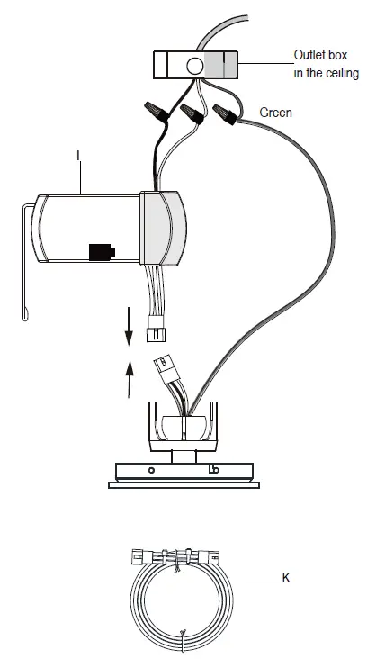
Wiring the fan to the receiver
- If using the 6 in. ball downrod assembly (B) provided, wire the receiver to the fan wires by connecting the molded adaptor plug from receiver (I) with molded adaptor of the fan motor assembly (E) together.
- If you wish to use longer downrod, you can use the extension lead wire (42 in.) (K) provided by connecting the molded adaptor together.
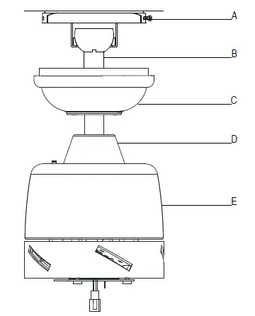
Mounting the fan-motor assembly (standard mount)
- Align the locking slots of the canopy (C) with the two screws (II) in the mounting bracket (A). Push up to engage the slots and turn clockwise to lock in place.
- Firmly tighten the two mounting screws (II).
- Install the two canopy screws (HH) (saved from Assembly Step 1 “Prepairing for mounting”) into the holes in the canopy (C) and tighten firmly.
- Install the decorative canopy ring (FF) by aligning the ring’s slots with the screws in the canopy (C). Rotate the ring clockwise to lock in place.
Attaching the blade to the motor
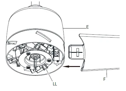
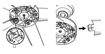
- Attach a blade (F) to the fan motor housing (E) by inserting the blade (F) into the slot in the side of the fan motor housing (E) until it stops. The locking clip (LL) will click when the blade is correctly installed. Ensure the blade is snapped into locking clip (LL) completely by pulling the fan blade away from the motor housing.
- Repeat these steps for the remaining blades (F).
Removing the blade from the motor
- To remove the blade (F) from the motor housing (E), squeeze the tabs of the locking clip (LL) towards each other and pull the fan blade away from the motor housing.
- Repeat these steps for the remaining blades (F).
Assembly – Attaching the Accessories
Attaching the light kit fitter assembly
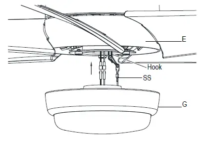
- Connect the wires from the light kit assembly (G) to the wires from the fan motor assembly (E) by connecting the molded adaptor plugs together. Carefully tuck all wires and splices into the switch cup and connect the safety cable (SS) from the light kit assembly (G) to the hook from motor assembly (E).
- Push the light kit assembly (G) up to the motor assembly (E) by aligning the magnet part of the motor assembly (E) till it is secure.
Operating Your Fan and Remote Control
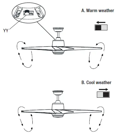
Remote Control – Your fan is equipped with a remote control to operate the speed and lights of your new ceiling fan. Speed setting for warm or cool weather depends on factors such as the room size, ceiling height, number of fans and so on. The fan is shipped from the factory with the reversing switch (YY) positioned to circulate air downward. If airflow is desired in the opposite direction, turn your fan off and wait for the blades to stop turning, then slide the reversing switch (located on the top of the motor housing) to the opposite position, and turn the fan on again. The fan blades will turn in the opposite direction and reverse airflow.
Warm weather – (Forward) A downward airflow creates a cooling effect. This allows you to set your air conditioner on a higher setting without affecting your comfort.
Cool weather – (Reverse) An upward airflow moves warm air off of the ceiling. This allows you to set your heating unit on a lower setting without affecting your comfort.
Power ON/OFF: Press and release the power button to turn the fan and light on or off.
Fan speed: LEDs on the fan speed button will illuminate to the corresponding speed.
- Press and release 1 time: turns the fan on high speed.
- Press and release 2 times: turns the fan on medium speed.
- Press and release 3 times: turns the fan on low speed.
- Press and release 4 times: turns the fan off.
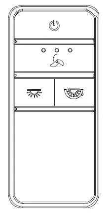
Light ON/OFF
Press and release the button to turn the light on or off. Press and hold the button to activate the dimmer function.
Correlated Color Temperature (CCT) changing
Push and release the button to cycle through the three color temperature options.
Option 1: 2700K (Warm White).
Option 2: 3000K (Soft White).
Option 3: 5000K (Daylight).
Care and Cleaning
- Because of the fan’s natural movement, some connections may become loose. Check the support connections, brackets, and blade attachments twice a year. Make sure they are secure. It is not necessary to remove the fan from the ceiling.
- Clean your fan periodically to help maintain its new appearance over the years. Do not use water when cleaning, as this could damage the motor, or the wood, or possibly cause an electrical shock. Use only a soft brush or lint-free cloth to avoid scratching the finish.
- You can apply a light coat of furniture polish to the wood for additional protection and enhanced beauty. Cover small scratches with a light application of shoe polish.
- You do not need to oil your fan. The motor has permanently-lubricated sealed ball bearings.
- To remove the blade from the motor housing, squeeze the tabs of the locking clip towards each other and pull the fan blade away from the motor housing (refer to page 11).
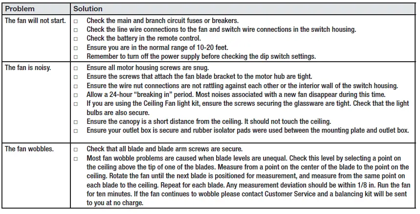
Troubleshooting
WARNING!
- To reduce the risk of personal injury, do not bend the blade brackets (also referred to as flanges) during assembly or after installation. Do not insert objects in the path of the blades.
- To reduce the risk of fire or electric shock, do not use this fan with any solid-state speed control device.
- To avoid possible electrical shock, turn the electricity off at the main fuse box before wiring. If you feel you do not have enough electrical wiring knowledge or experience, contact a licensed electrician.
- To reduce the risk of fire, electric shock or personal injury, mount to outlet box marked “Acceptable for fan support of 35 lbs. (15.9 kg) or less”, and use screws provided with the outlet box.
- Electrical diagrams are for reference only. If you are using a light kit, refer to the light kit instructions manual to make the electrical connections. Optional use of any light kit shall be UL-listed and marked suitable for use with this fan.
- To reduce the risk of fire or electric shock, this fan should only be used with fan speed control part no. AP-8RDL, manufactured by Dawnsun Electronic Co., LTD.
- To reduce the risk of electric shock, this fan must be installed with an isolating wall switch.
Warranty
The supplier warrants the fan motor to be free from defects in workmanship and material present at time of shipment from the factory for a lifetime after the date of purchase by the original purchaser. The supplier warrants that the light kit, excluding any glass, to be free from defects in workmanship and material at the time of shipment from the factory for a period of five years after the date of purchase by the original purchaser. The supplier also warrants that all other fan parts, excluding any glass or acrylic blades, to be free from defects in workmanship and material at the time of shipment from the factory for a period of three years after the date of purchase by the original purchaser. We agree to correct such defects without charge or at our option replace with a comparable or superior model if the product is returned. To obtain warranty service, you must present a copy of the receipt as proof of purchase. All costs of removing and reinstalling the product are your responsibility. Damage to any part, such as by accident, misuse, improper installation, or by affixing any accessories, is not covered by this warranty. Because of varying climatic conditions this warranty does not cover any changes in brass finish, including rusting, pitting, corroding, tarnishing, or peeling. Brass finishes of this type give their longest useful life when protected from varying weather conditions. A certain amount of “wobble” is normal and should not be considered a defect. Servicing performed by unauthorized persons shall render the warranty invalid. There is no other express warranty. Interline hereby disclaims any and all warranties, including but not limited to those of merchantability and fitness for a particular purpose to the extent permitted by law. The duration of any implied warranty which cannot be disclaimed is limited to the time period as specified in the express warranty. Some states do not allow a limitation on how long an implied warranty lasts, so the above limitation may not apply to you. The retailer shall not be liable for incidental, consequential, or special damages arising out of or in connection with product use or performance except as may otherwise be accorded by law. Some states do not allow the exclusion of incidental or consequential damages, so the above exclusion or limitation may not apply to you. This warranty gives specific legal rights, and you may also have other rights which vary from state to state. This warranty supersedes all prior warranties. Shipping costs for any return of product as part of a claim on the warranty must be paid by the customer.
Contact the Customer Service Team at 1-855-HD-HAMPTON or visit www.HamptonBay.com