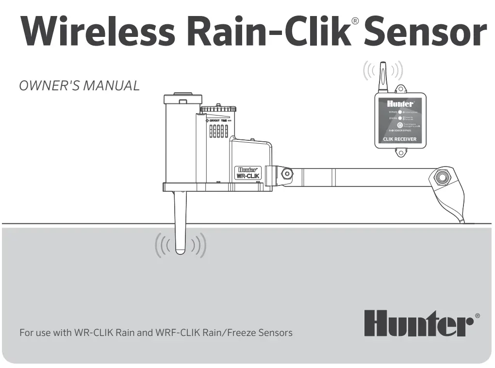
Hunter Wireless Rain-Clik Sensor
Owner's Manual
Need more helpful information on your product? Find tips on installation, controller programming, and more.
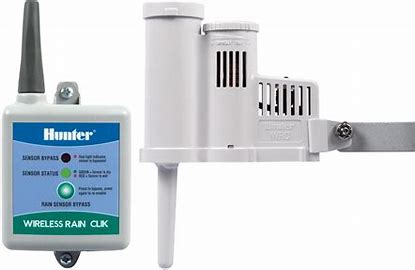
Wireless Rain-Clik Features
To prevent water waste, built-in Quick Response® Technology instantly shuts down irrigation as soon as it starts raining.
Key Benefits
- Quick Response: Innovative technology that turns off the irrigation system immediately rather than after it has accumulated a fixed amount of rain. No calibration is required.
- Maintenance-Free Design: Provides trouble-free operation for at least 5 years. There are no batteries to replace.
- Wireless Operation Up to 800′ (243 m): No wires are required between the rain sensor and controller.
- Wireless Rain-Clik Sensor (WR-CLIK): Acts as a switch to deactivate automatic watering of your irrigation controller when it rains. Once rain has stopped and the sensor has dried out, automatic irrigation will resume.
- Wireless Rain/Freeze-Clik Sensor (WRF-CLIK): The Wireless Rain/Freeze-Clik includes a freeze sensor that is designed to keep the irrigation system from operating when temperatures drop to 37°F (3°C) or below. When temperatures rise above this temperature, the sensor will enable automatic watering.
- Automatic Synchronization: The Wireless Rain-Clik transmitter will send wireless signals every hour to the receiver to ensure that the sensor and receiver are continuously synchronized.
- Lost Communication/Battery Status Indication: The Sensor Bypass LED will flash RED if the receiver has not received a signal from the transmitter. This can indicate a low or dead battery.
Wireless Rain-Clik Components
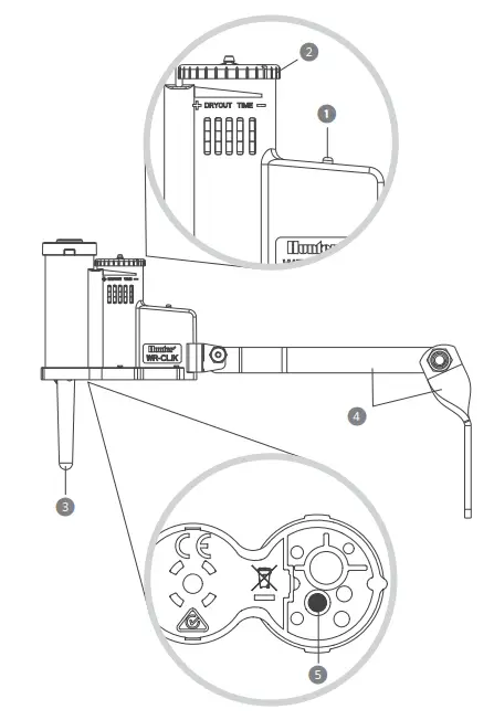
Wireless Rain-Clik Sensor
- Manual Test Spindle: Press and hold the manual test spindle to confirm proper operation of your transmitter.
- Vent Ring: Used to adjust the reset rate or dry out time for the sensors. Opening the vents will decrease the reset rate, while closing the vents will increase the time it takes for the discs to dry out.
- Radio Antenna: Transmits a wireless signal to the receiver up to 800′ (243 m). The antenna should be oriented vertically.
- Mounting Arm: Metal extension arm for mounting the sensor.
- Battery Status LED: Used to determine the status of the sealed battery. Pushing the manual test spindle will flash the LED light indicating that the battery is good.

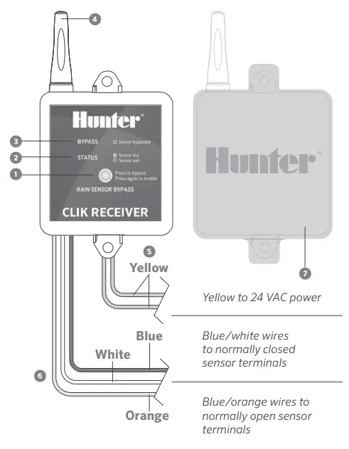
Wireless Receiver
- Bypass Button: Allows automatic or manual watering when the sensor is active.
- Receiver Status LED: Used to indicate the status of the sensor.
- Receiver Bypass LED: Indicates when sensor has been bypassed.
- Radio Antenna: Receives a wireless signal from the transmitter up to 800′ (243 m) line-of-sight. The antenna should be oriented vertically.
- AC Power Wires: The two yellow wires are attached to a 24 VAC source from the controller.
- Receiver Wires: The sensor wires are attached to either the sensor terminals in the controller or in-line with the valve common wire.
• Blue/White Wires: Used for normally closed sensor applications (Hunter controllers).
• Blue/Orange Wires: Used for normally open sensor applications. - Rubber Cover: Used to protect the receiver when mounted in outdoor locations.
Mounting the Receiver
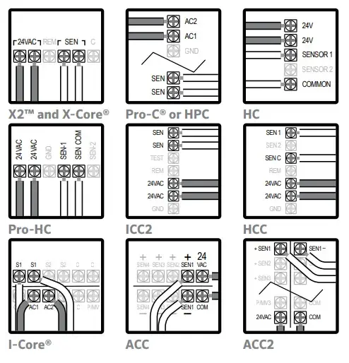
Wiring the Receiver to Hunter Controllers
- Remove the sensor jumper across the two SEN terminals in the controller.
- Attach the two yellow wires to the 24 VAC terminals.
- Attach the blue wire to one SEN terminal and the white wire to the other SEN or SEN COM terminal.
(i) Note: Additional setup steps required for Hydrawise®, ACC, and ACC2 controllers.
- Hydrawise Controllers: Complete the installation by configuring the sensor in your Hydrawise account.
- ACC Controllers: Use features at the “Set Sensor Operation” dial position on ACC to complete setup.
- ACC2 Controllers: Use “Devices and Sensor Response” options on ACC2 to complete setup.
https://hunter.help/hydrawisesensor
https://hunter.help/acc2sensor
Wiring the Receiver to Other Controllers: Normally Closed Sensor Applications
- Attach the two yellow wires to the 24 VAC terminals.
- Attach the blue and white wires to the sensor terminals (if available) or in-line with the valve common wire.
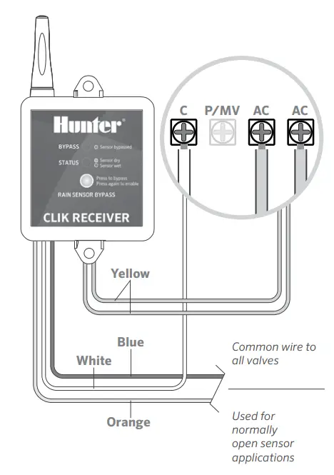
Wiring the Receiver to Other Controllers: Normally Open Sensor Applications
- Attach the two yellow wires to the 24 VAC terminals.
- Attach the blue and orange wires to the sensor input.

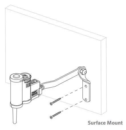
Surface Mounting
Using the screws provided with your sensor, mount the transmitter on any surface where it will be exposed to unobstructed rainfall, but not in the path of sprinkler spray. The sensor should be oriented upright (as pictured), but the swivel bracket can be moved for mounting on any angled surface. Loosen the locknut and screw before swiveling the bracket, and then re-tighten.
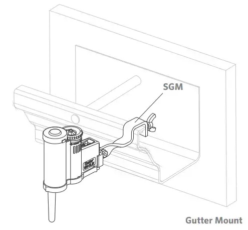
Gutter Mounting
The SGM allows the transmitter to be mounted directly to the edge of a gutter. Install the SGM on the transmitter by removing the metal extension arm supplied with your sensor and reinstalling the SGM. Position the gutter mount on the edge of the gutter and twist the thumbscrew to secure it in place.
Adjustments and Operation
Tips for Mounting the Sensor
- Choose a location such as the side of a building or post. The closer the transmitter is to the receiver, the better the reception. Do not exceed 800′ (243 m).
- To ensure maximum range in communication, mount the receiver and transmitter away from sources of electrical interference (e.g., control panels, transformers, etc.) or metal objects. Best performance is obtained when no physical obstruction is between the transmitter and receiver.
- Correct placement of the Wireless Rain/Freeze-Clik model is important for accurate temperature sensing. The best location would be out of direct sunlight.
- The reset rate refers to the amount of time it takes for the sensor to dry out sufficiently for the sprinkler system to be allowed to come back on. The mounting location will affect this rate. For example, mounting the transmitter in a very sunny location may cause the sensor to dry out sooner than desired. Similarly, mounting the sensor in constant shade may keep the sensor from drying out sooner.
Receiver Operation
The receiver has two LED lights that indicate the state of the system.
- SENSOR STATUS LED:
RED – Sensor is wet (watering disabled).
GREEN – Sensor is dry (watering enabled).
YELLOW – Sensor is in addressing mode. - SENSOR BYPASS LED:
RED – Rain sensor is bypassed (even though the sensor is bypassed, the STATUS LED will continue to alert you of the state of the sensor — wet or dry).
OFF – Rain sensor is enabled.
FLASHING RED – Indicates that communication between the transmitter and receiver was lost.
(!) Note
When you first apply power to the receiver, the SENSOR STATUS LED will be RED. Press the manual test spindle on the transmitter for five seconds and release the spindle. The SENSOR STATUS LED will turn GREEN indicating proper operation.
Bypassing the Sensor
The sensor can be bypassed by using the built-in bypass feature on the receiver. To bypass the sensor, press the SENSOR BYPASS button on the receiver. The bypass status light will turn red when the sensor is bypassed. Pressing the SENSOR BYPASS button again will re-enable the sensor and the sensor bypass light will go out.
Setting the Transmitter Address at the Receiver
Each transmitter is produced with a unique address. A receiver must learn this address to work with that transmitter. This step is only necessary if transmitters and receivers are purchased separately.
(!) Note
Units purchased as a kit will already have their communication address preset. No addressing is necessary. However, if the receiver or transmitter is replaced you need to reset the address.
- Prior to applying power (yellow wires) to the receiver, press and hold the bypass button on the receiver.
- While the bypass button is depressed, apply power to the receiver. The sensor status indicator light should light up yellow indicating that the receiver is ready to learn a new address.
- Press and hold the quick response button on the transmitter.
- Within four seconds, the receiver’s sensor status indicator light should turn red. The receiver has now learned the address and it will be retained even in the event of a power outage.
- Release the button on the transmitter. The sensor status indicator light should turn green.
Battery Life
The Wireless Rain-Clik Transmitter is designed to operate for at least 5 years with its sealed, maintenance-free battery. The transmitter is available as a replacement part (WR-CLIK-TR). Should you need to change the transmitter, the receiver will have to learn the new transmitter address.
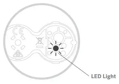
To Check the Status of the Battery in the Transmitter
- Press and hold the quick response spindle at the top of the sensor on the short stack.
- Within a few seconds the LED light on the bottom of the sensor will briefly flash.
- Release the spindle and the LED light will flash again.
If you are experiencing problems with your Wireless Rain-Clik Sensor, follow these simple checks first before assuming the unit is defective and replacing it.
System Will Not Turn On at All
- Check to make sure that the sensor discs are dry and the switch “clicks” on and off freely by pressing the top of the spindle.
- Look for breaks in the wire leading to the receiver and check all connections.
- Verify outside air temperature (for Rain/Freeze-Clik installations).
System Will Not Shut Off Even After Heavy Rainfall
- Remove the sensor jumper across the two SEN terminals.
- Check to make sure that rainfall is hitting the sensor.
- Look for breaks in the wire leading to the receiver and check all connections.
- Check the battery in the transmitter.
Sensor Bypass LED Is Flashing Red
- Make sure the battery in the transmitter is good.
- Check for obstructions around the transmitter or receiver antenna.
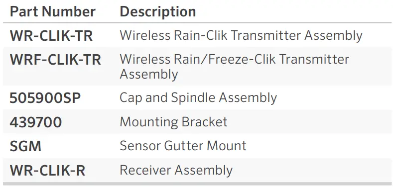
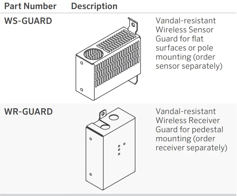
Replacement Parts and User-Installed Options
REPLACEMENT PARTS

USER-INSTALLED OPTIONS
Notices
FCC Notice
This device complies with part 15 of the FCC Rules. Operation is subject to the following two conditions: (1) This device may not cause harmful interference, and (2) this device must accept any interference received, including interference that may cause undesired operation.
This equipment has been tested and found to comply with the limits for a Class B digital device pursuant to Part 15 of the FCC Rules. These limits are designed to provide reasonable protection against harmful interference in a residential installation. This equipment generates, uses, and can radiate radio frequency energy and, if not installed and used in accordance with the instructions, may cause harmful interference to radio communications. However, there is no guarantee that interference will not occur in a particular installation. If this equipment does cause harmful interference to radio or television reception, which can be determined by turning the equipment off and on, you are encouraged to try to correct the interference by taking one or more of the following measures:
- Reorient or relocate the receiving antenna.
- Increase the separation between the equipment and receiver.
- Connect the equipment into an outlet on a circuit different from that of which the receiver is connected.
- Consult the dealer or an experienced radio/TV technician for help.
Changes or modifications not expressly approved by Hunter Industries could void the user’s authority to operate this device. If necessary, consult a representative of Hunter Industries Inc. or an experienced radio/television technician for additional suggestions.
Innovation, Science and Economic Development Canada (ISED) Compliance Notice
This device contains licence-exempt transmitter(s)/ receiver(s) that comply with Innovation, Science and Economic Development Canada’s licence-exempt RSS(s). Operation is subject to the following two conditions:
- This device may not cause interference.
- This device must accept any interference, including interference that may cause undesired operation of the device.
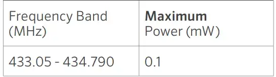
MAXIMUM OUTPUT POWER
CE
Hereby, Hunter Industries declares that the radio equipment type models WR-CLIK-TR are in compliance with Directive 2014/53/EU.
The full text of the EU declaration of conformity is available at the following internet address: http://subsite.hunterindustries.com/compliance
Notes
_________________________________________________________________________________________________________________________________________________________________________________________________________________________________________________________________________________________________________________________________________________________________________________________________________________________________________________________________________________________________________________________________________________________________________
Helping our customers succeed is what drives us. While our passion for innovation and engineering is built into everything we do, it is our commitment to exceptional support that we hope will keep you in the Hunter family of customers for years to come.

HUNTER INDUSTRIES | Built on Innovation® 1940 Diamond Street, San Marcos, CA 92078 USA hunterindustries.com
© 2021 Hunter Industries™ Hunter, the Hunter logo, and all other trademarks are property of Hunter Industries, registered in the U.S. and other countries.
P/N 715182 23-594 I EN 5/21