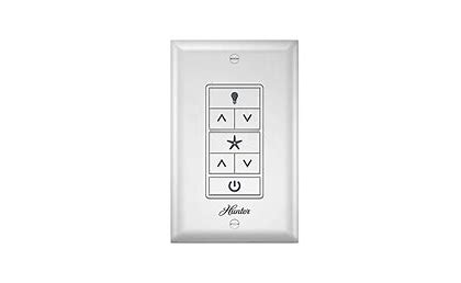
CEILING FAN REMOTE WALL CONTROL
Model 99373, 99375
Installation
- Turning off the power
Before installation, use the pull chains to set the fan speed to HIGH and the light to ON. Ensure the power is OFF at the outlet box and wall switch location before proceeding with the installation.

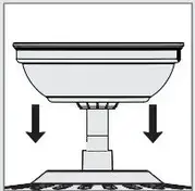
- Removing the canopy
Remove the canopy. If uncertain how to remove it, reference the fan’s owner’s manual. With wiring exposed, it may be helpful to note existing wire connections or take a digital photo for reference. Remove the wire connectors that connect the wires from the outlet box to the fan, leaving the grounding wires connected.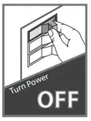
- Installing the receiver
Choose the hanging system that most closely resembles the one used by your fan, and install the receiver and wire as directed. You may have installation issues if the fan is
installed on an angled ceiling. For assistance, call 1-888-830-1326.
 Note: Some fans may have considerable excess lead wire. For easier canopy installation, cut the excess wire, leaving a minimum of 8” remaining. Re-strip the fan lead wires 1/2”. Place remaining excess wire into the ceiling electrical box. The bracket and fan must remain properly grounded.
 - Wiring the receiver to the fan
Using the orange wire connectors, connect the blue wire from the receiver to the blue wire (or possibly black with white stripe wire) from the fan. Connect the yellow wire from the receiver to the black wire from the fan.
Note: If you are uncertain about wire colors or connections, please contact a qualified electrician.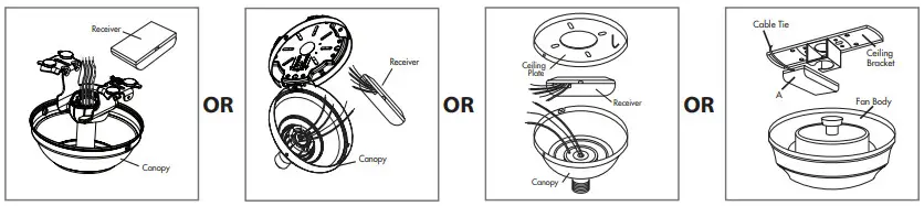
 To avoid possible electrical shock, before installing or servicing your fan, disconnect the power by turning off the circuit breakers to the outlet box and associated wall switch location. If you cannot lock the circuit breakers in the off position, securely fasten a prominent warning device, such as a tag, to the service panel.
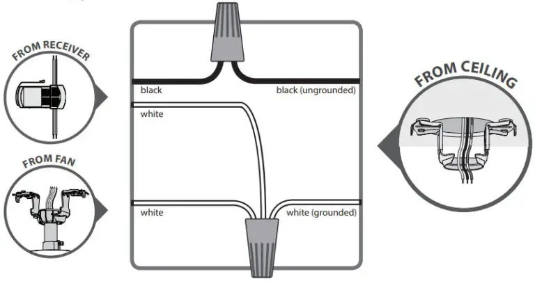
 - Wiring the receiver and fan to the ceiling
Using the orange wire connectors, connect the black wire (ungrounded) from the ceiling to the black wire from the receiver. Connect the white wire (grounded) from the ceiling to both the white wire from the receiver and the white wire from the fan.
AFTER ALL, WIRES ARE CONNECTED and secured with wire connectors, re-install the canopy. Turn the splices upward and push them carefully back through the hanger bracket into the outlet box. Spread the wires apart, with the grounded wires on one side of the outlet box and the ungrounded wires on the other side of the outlet box.
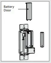
 - Installing the battery
To access the battery compartment, slide the battery door up.
Replace the used battery with two AAA batteries when needed.
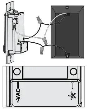
- Wiring the Wall Control
1. Connect the grounding wire from the wall control to the ground control from the switch box using the provided wire nuts.
2. Connect the “LIVE IN” from the switch box to the “~VAC” from the wall control using the provided wire nuts.
3. Connect the “LIVE OUT” from the switch box to the “FAN” out from the wall control using the provided wire nuts.
4. Push all wires into the switch box.
- Installing the Wall Control
Install the longer screws through switch box screw holes.the slots in the wall control into the.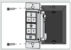
- Installing the Wall Plate
Install the shorter screws through the wall control plate and into the screw holes in the wall control.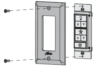
- Turning on the power
 IMPORTANT
Use the pull-chain switch on the fan to set the fan speed to the HIGH position before operation.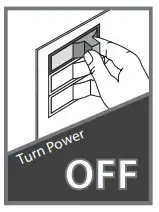
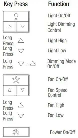
- Reference the included remote function card for information on how to use your wall control!
Remote Function Guide
The Hunter Fan Company makes the following limited warranty to the original purchaser of the Control (“Control”): Your Control is warranted to be free from defects in material and workmanship for a period of one year from the date of sale. If the Control malfunctions or fails within the warranty period due to a defect in material or workmanship we will replace it free of charge. IF THE ORIGINAL PURCHASER CEASES TO OWN THE CONTROL, THIS WARRANTY AND ANY IMPLIED WARRANTY, INCLUDING BUT NOT LIMITED TO ANY IMPLIED WARRANTY OF MERCHANTABILITY OR FITNESS FOR A PARTICULAR PURPOSE, ARE VOIDED. THIS WARRANTY IS IN LIEU OF ALL OTHER EXPRESS WARRANTIES. THE DURATION OF ANY IMPLIED WARRANTY, INCLUDING, BUT NOT LIMITED TO, ANY IMPLIED WARRANTY OF MERCHANTABILITY OR FITNESS FOR A PARTICULAR PURPOSE, IN RESPECT TO ANY CONTROL, IS EXPRESSLY LIMITED TO THE PERIOD OF THE EXPRESS WARRANTY SET FORTH ABOVE FOR SUCH CONTROL. This warranty excludes malfunctions or failures which were caused by repairs by persons not authorized by us, mishandling, improper installation, modifications, or damage to the Control while in your possession, or unreasonable use. This warranty does not apply to batteries or to deterioration or damage to the product caused by the use of faulty batteries. To obtain a replacement, return your Control postage prepaid along with proof of purchase to Hunter Fan Company Service Department at 7130 Goodlett Farms Pkwy., Memphis, TN 38016. IN NO EVENT SHALL HUNTER FAN COMPANY BE LIABLE FOR CONSEQUENTIAL OR INCIDENTAL DAMAGES. SOME STATES DO NOT ALLOW LIMITATIONS ON HOW LONG AN IMPLIED WARRANTY LASTS OR THE EXCLUSION OR LIMITATIONS OF INCIDENTAL OR CONSEQUENTIAL DAMAGES SO THE ABOVE LIMITATIONS OR EXCLUSIONS MAY NOT APPLY TO YOU. THIS WARRANTY GIVES YOU SPECIFIC LEGAL RIGHTS AND YOU MAY ALSO HAVE OTHER RIGHTS WHICH VARY FROM STATE TO STATE.
Read and Save These Instructions
This product conforms to UL Standard 1917.
 WARNINGS
This device complies with part 15 of the FCC Rules. Operation is subject to the following two conditions: (1) this device may not cause harmful interference, and (2) this device must accept any interference received, including interference that may cause undesired operation.
This device complies with RSS-210 of Industry Canada. Operation is subject to the following two conditions: (1) this device may not cause interference, and (2) this device must accept any interference, including interference that may cause undesired operation of the device.
This equipment has been tested and found to comply with the limits for a Class B digital device, pursuant to Part 15 of the FCC Rules. These limits are designed to provide reasonable protection against harmful interference in a residential installation. This equipment generates, uses and can radiate radio frequency energy and, if not installed and used in accordance with the instructions, may cause harmful interference to radio communications. However there is no guarantee that interference will not occur in a particular installation. If this equipment does cause harmful interference to radio or television reception, which can be determined by turning the equipment off and on, the user is encouraged to try to correct the interference by one or more of the following measures: Reorient or relocate the receiving antenna, Increase the separation between the quipment and receiver, Connect the equipment into an outlet on a circuit different from that to which the receiver is connected. Consult the dealer or an experienced radio/TV technician for help. Note: Any changes or modifications to the transmitter or receiver not expressly approved by Hunter Fan Company may void one’s authority to operate this remote control.
If you are installing multiple remote-controlled fans on the same circuit breaker,
you may need to perform a few extra steps to prevent interference or faulty operation of your remote controls.
Go to www.HunterFan.com/FAQs and click “How do I properly install multiple remote-controlled fans?” for more information.