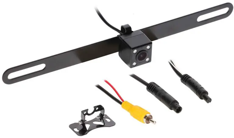
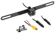
Part Components
- Camera
- License plate and surface mount
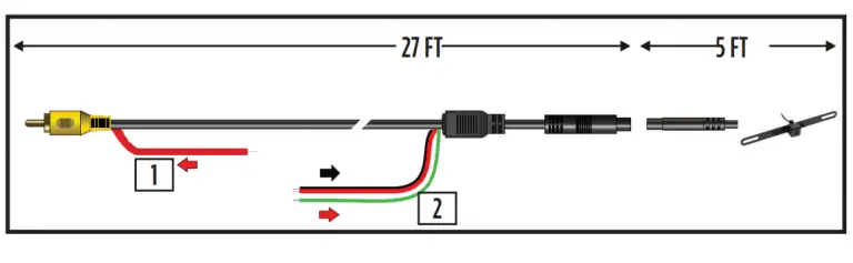
- Extension harness (27 FT)
- Screws
TOOLS REQUIRED
- Wire stripper
- Tape
- Digital Multi-meter
- Cutter
When testing the aftermarket equipment, ensure that all factory equipment is connected before cycling the key to ignition.
Product Features
- Multiple mounts included – license plate and surface mount
- Improved power circuit
- Can be viewed while driving with compartible monitor
- Ability to trigger IRs separetely from the camera’s power
- Water resistant – IP67
- 3 year warranty
Multi-Mounting Options
- License plate mount

- Surface mount
CAMERA WIRING
- Connect the RED wire labeled 12V acc. to the vehicles ignition.
- Connect the BLACK wire labeled Ground to chassis ground.
Connect one GREEN wire labeled TRIGGER to the vehicles reverse wire
- Applying 12 volts to this wire activates the IRs and Parking lines when in reverse.
- This wire can be used if reverse is needed at the opposite end of the vehicle, EX. activating rear camera on an aftermarket radio.
- If not using the opposite end of the wire, please cover/cap off the wire so it will not short out and damage the camera.
CAMERA WIRING MOUTNING OPTIONS
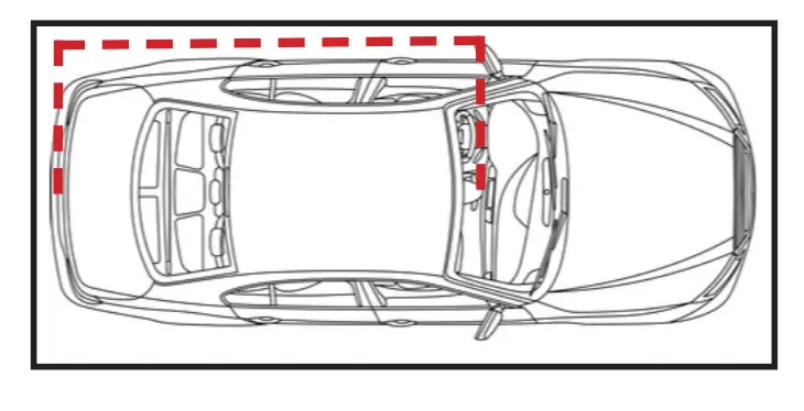
- Run the extension cable to the front of the vehicle. (Figure A)
- Connect the YELLOW RCA to the backup camera or video input of the monitor
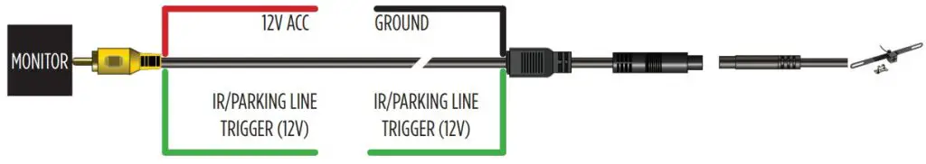
Figure A
This camera comes with two mounting options.
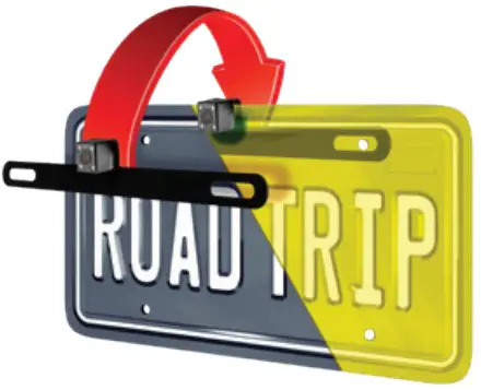
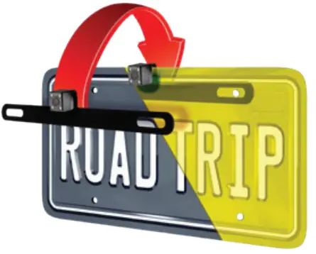
- Behind license plate mount (Figure B)
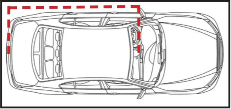
Figure B
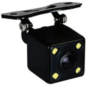
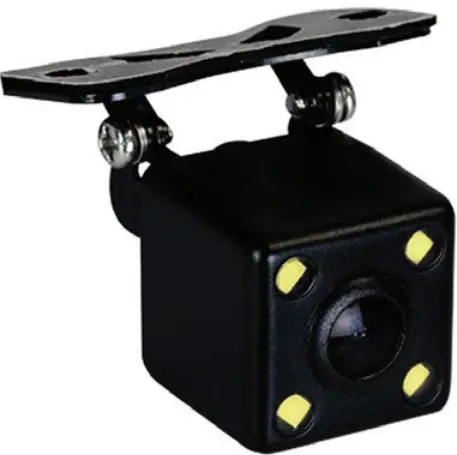
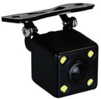
- Surface mount (Figure C)
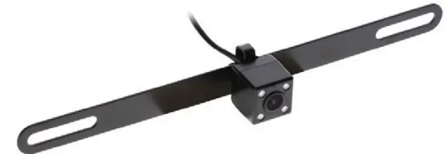
Figure C
Using the two small phillips head screws on the rear of the camera, the mounts can be switched.
Photo shows camera in both mounting options, 1 camera in box.
Specifications
| Sensor | CMOS II |
| Effective Pixel | 648 X 488 |
| Sync Frequency | NTSC 60 HZ |
| Resolution | 420 TV Lines |
| S/N Ratio | More than 48dB |
| Current Consumption | No more than 150mA |
| Power Supply | DC 12V +- 10% |
| Operating Temp | -22 ~ 176 F |
| Storage Temp. | -40 ~ 176 F |
| Viewing Angle (Dia.) | 170 |
| Water Resistance | IP67 |
| Min. Illumination | 0.5/F1.2 LUX – 0 LUX IRs on |
Contact Us
Having difficulties? We’re here to help.
Contact our Tech Support line at: 386-257-1187
Or via email at: [email protected]
Tech Support Hours (Eastern Standard Time)
Monday – Friday: 9:00 AM – 7:00 PM
Saturday: 10:00 AM – 7:00 PM
Sunday: 10:00 AM – 4:00 PM
 KNOWLEDGE IS POWER
Enhance your installation and fabrication skills by enrolling in the most recognized and respected mobile electronics school in our industry.
Log onto www.installerinstitute.com or call 800-354-6782 for more information and take steps toward a better tomorrow.
Metra Recommends MECP certified technicians

Scan QR Code

Product Features
- Multiple mounts included – license plate and surface mount
- Improved power circuit
- Can be viewed while driving with compartible monitor
- Ability to trigger LEDs separetely from the camera’s power
- Water resistant – IP67
- Active parking lines
- 3 year warranty
Part Components
- Camera
- License plate and surface mount
- Extension harness (27 FT)
- Screws
TOOLS REQUIRED
- Wire stripper
- Tape
- Digital Multi-meter
- Cutter
Attention!
When testing the aftermarket equipment, ensure that all factory equipment is connected before cycling the key to ignition.
Multi-Mounting Options
- License plate mount
- Surface mount
CAMERA WIRING
Camera Wiring
There are two options for powering up the camera.This camera can be powered to be available while the vehicle is running or to only be used as a back-up camera.
Power camera with reverse
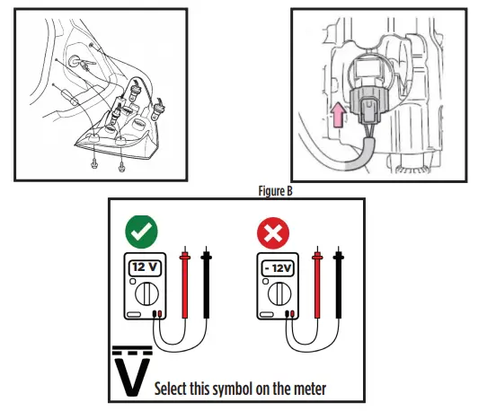
- Remove the tail light from the vehicle to allow access to the light bulbs wiring. (If help is needed, review the vehicles owners manual section on replacing the tail light bulbs.) (Figure A)
- Find the wiring that connects to the reverse bulb.There is normally 2 wires. (Figure B)
- Using a Digital Multi-meter on the DC Voltage setting, to verify the reverse wire. (Figure C)
- Connect the RED wire labeled +12V to the reverse wire.
Connect the BLACK wire to a chassis ground. NOTE: If lighting circuit has pulse width modulation, please use part # TE-CAMFLTR.
Power camera with accessory
- Find a reliable 12 volt accessory source in the vehicle. This can be found at the radio if it is being replaced with an aftermarket radio. 2
- Using a Digital Multi-meter on the DC Voltage setting, to verify the accessory wire. (Figure C)
- Connect the RED wire labeled +12V to the accessory wire. Connect the BLACK wire to a chassis ground.
CAMERA WIRING (CONT.)
- Connect the GREEN wire labeled Trigger to a reverse line in the vehicle. This wire will be used to trigger the LEDs on the camera. (Figure B.2)
- Run the extension cable to the front of the vehicle. (Figure A)
- The RED wire on the YELLOW RCA can be used in different ways. This wire is the same RED wire that is at the other end of the extension cable. (Figure B.1)
- If connected to REVERSE in the rear, the RED wire at the YELLOW RCA can be used as a reverse trigger for a monitor, mirror or aftermarket radio.
- If connected to 12 volt accessory in the rear, please cap off this wire on the YELLOW RCA.
- If a REVERSE or 12 volt accessory could not be found in the rear of the vehicle, this wire can be used to power the camera. If this solution is used, cap off the RED wire in the rear.
- Connect the YELLOW RCA to the backup camera or video input of the monitor.
NOTE: Active parking lines will still be active if camera is powered on by ignition.
| Sensor | CMOS II |
| Effective Pixel | 736 X 592 |
| Sync Frequency | NTSC 60 HZ |
| Resolution | 600 TV Lines |
| S/N Ratio | More than 48dB |
| Current Consumption | No more than 280mW |
| Power Supply | DC 12V +- 10% |
| Operating Temp. | -22 ~ 176 F |
| Storage Temp. | -40 ~ 176 F |
| Viewing Angle (Dia.) | 170 |
| Water Resistance | IP67 |
| Min. Illumination | 0.5/F1.2 LUX – 0 LUX LEDs on |
Having difficulties? We’re here to help.
 Contact our Tech Support line at: 386-257-1187
Or via email at: [email protected]
Tech Support Hours (Eastern Standard Time)
Monday – Friday: 9:00 AM – 7:00 PM
Saturday: 10:00 AM – 7:00 PM
Sunday: 10:00 AM – 4:00 PM
 KNOWLEDGE IS POWER
Enhance your installation and fabrication skills by enrolling in the most recognized and respected mobile electronics school in our industry. Log onto www.installerinstitute.com or call 800-354-6782 for more information and take steps toward a better tomorrow.
Metra Recommends MECP certified technicians

TE-2MPLTC INSTALLATION INSTRUCTIONS #IBEAMSAFETY