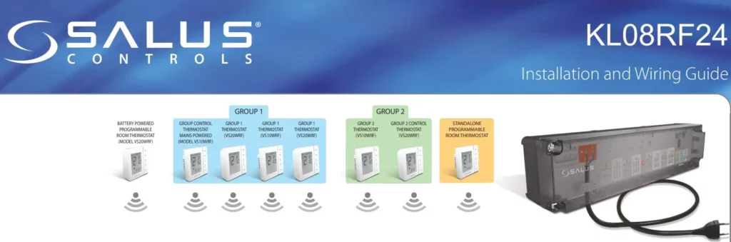
SALUS KL08RF24 UPC Wireless Control
Box Installation Guide
Installing and Connecting the KL08RF24
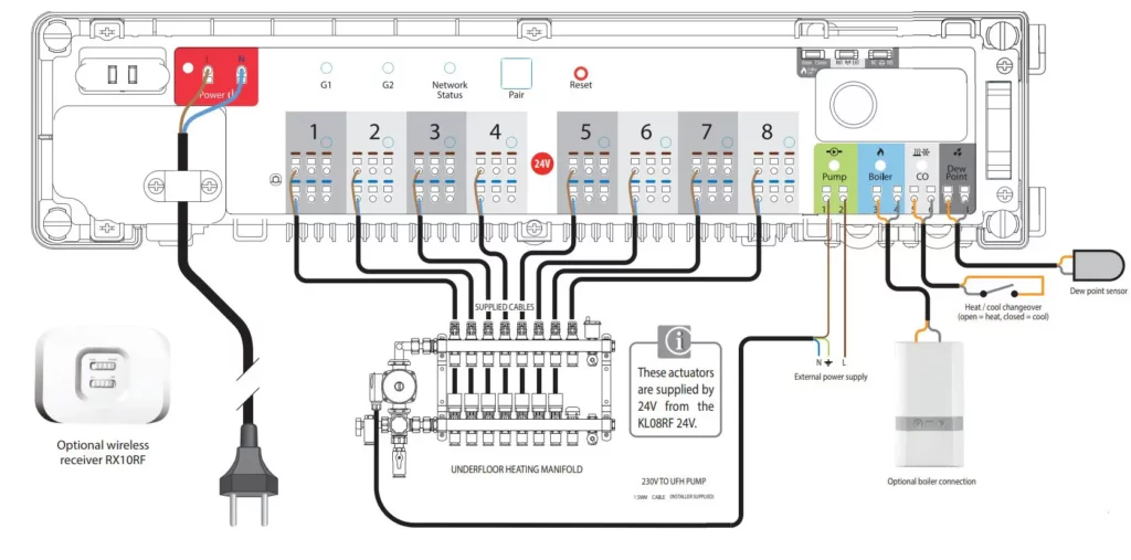
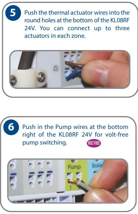
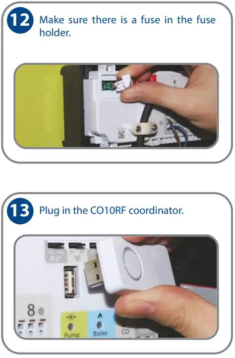
Use the KL08RF 24V wireless wiring centre to simply and safely connect thermostats and corresponding thermal actuators. The KL08RF connects to the wireless network through the CO10RF coordinator. One coordinator can support up to nine wiring centres, which means that if you buy more than one wiring centre, you will only need one of the included coordinators. Keep the other coordinators in a safe place as spares. Install the KL08RF 24V only in dry and closed interior rooms. Relative air humidity in the room may not exceed 95%. Clean the KL08RF 24V only with a dry and soft cloth. Do not use solvents or aggressive cleaning agents.
(11) Set the boiler delay, wireless, and thermal actuator jumpers at the top right of the KL08RF.
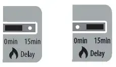
Jumper Settings/Positions for Pump/Boiler On/Off Delay
The pump/boiler on delay and the pump off delay are fixed at three minutes. The default setting for the boiler off delay is also zero minutes, but can be changed to 15 minutes. To do this, carefully remove the jumper and re-insert it in the other position as shown below:
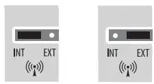
Wireless
The default setting for the wireless connection is internal (INT). To change this setting to external (EXT), carefully remove the jumper and re-insert it in the other position as shown below:
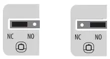
Type of Actuator
The default setting for the type of actuator is normally closed (NC). To change this setting to normally open (NO), carefully remove the jumper and re-insert it in the other position as shown below. Note that the actuator setting and thermostat setting must be the same.
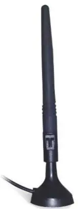
(16) If you need to install the optional external antenna and have set the
Wireless jumpers to EXT:
- a. Disconnect power.
- b. Remove the protective cap from the antenna connection on the underside of the KL08RF 24V.
- c. Screw the antenna into the KL08RF 24V.
- d. Reconnect power. The KL08RF 24V will now use the external antenna and not the internal antenna.
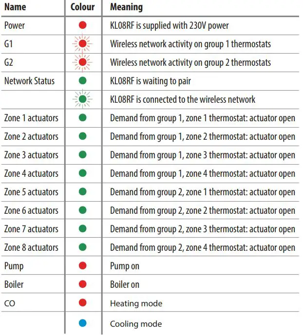
LED indications
Connecting the KL08RF 24V (s) to the ZigBee Wireless Network
- On powering up the KL08RF 24V, all actuator LEDs light up green then go off, then the Network Status LED flashes green.
- Press and hold the button on the coordinator for five seconds. The button flashes red to indicate the coordinator is ready to pair.
The Network Status LED on the KL08RF 24V goes steady green when connected. - Repeat the process for every KL08RF 24V in the system. Note that one coordinator can support up to nine KL08RFs.
- To identify your KL08RF 24V (WC) number press Pair for one second.
The LED on the zone number lights green: Zone 1 = WC -1, Zone 2 = WC-2, and so on. The Network Status LED is used to identify WC-9. - To pair your VS10RF or VS20RF thermostats, see your thermostat manual.
- Press the coordinator button for five seconds until the LED shines steady red.
Note: To restore the KL08RF 24V back to factory default settings at any time, using a suitable tool, press the Reset button to the right of the Pair button.
Checking the System Configuration and Communication
- Press and hold the coordinator button for one second. All devices connected to the system flash. To stop checking, press and hold the coordinator button again for one second.
- Press and hold the Pair button on the WC for five seconds. All devices connected to the KL08RF 24V flash. To stop checking, press and hold the Pair button again for five seconds.
Deleting all Devices from the Wireless Network - To delete all devices connected to the network, press and hold the coordinator button for 15 seconds. The colour of the button changes from red to amber.
- To delete all devices connected to the KL08RF 24V, press and hold the Network Status button on the KL08RF 24V for 15 seconds. The G1 and G2 LEDs turn from flashing red to solid red then go off.
Note: After all devices have been deleted from the wireless network, they will need to be reinstalled. Refer to the instruction manuals.
Note: After all devices have been deleted from the wireless network, they will need to be reinstalled. Refer to the instruction manuals.
Meets the following EC Directives
- Electro-Magntic Compatibility directive 2004 / 108 / EC
- Low-voltage Directive 2006/95/EC
These instructions apply to the SALUS model stated above.
![]() Warning
Warning
This product must be fitted by a competent person, and installation must comply with the guidance, standards and regulations applicable to the country or state where the product is installed. Failure to comply with the requirements of the relevant guidance, standards and regulations could lead to injury, death or prosecution.
![]() For PDF Installation guide go to www.salus-controls.com
For PDF Installation guide go to www.salus-controls.com
Maintaining a policy of continued product development SALUS Controls plc reserves the right to change specification, design and materials of products listed on this installation guide without prior notice.
Issue Date: October 2014 Document Number 00106
www.salus-controls.com
Technical Helpline +44 (0) 1226 323 961