![]() Installation Manual
Installation Manual
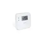
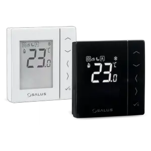
Programmable, wired thermostat with digital display for the control of temperature in UFH & RAD systems
Model: VS30W (white), VS30B (black)
IMPORTER:
QL CONTROLS Sp. z o.o. Sp. k.
ul. Rolna 4, 43-262 Kobielice
PRODUCER:
Salus Limited
6/F, Building 20E, Phase 3, Hong Kong
Science Park, 20 Science Park East Avenue,
Shatin, New Territories, Hong Kong
www.salus-controls.eu
SALUS Controls is a member of the Computime Group
Maintaining a policy of continuous product development SALUS Controls plc reserve the right to change specification, design, and materials of products listed in this brochure without prior notice.
Introduction
The VS30 thermostat controls temperatures of the individual heating zone in underfloor heating systems. The thermostat allows for significant savings thanks to the possibility of maximum reduction the set temperature.
The full version of the manual in PDF format is available on the website www.salus-controls.eu
Product Compliance
This product complies with the following EU Directives: Electromagnetic Compatibility 2014/30/EU, Low Voltage Directive 2014/35/EU and RoHS 2011/65/EU. Full information is available on the website www.saluslegal.com

Use in accordance with national and EU regulations. Use the device only as intended, keeping it in a dry condition. The product is for indoor use only. Installation must be carried out by a qualified person in accordance with national and EU regulations.
Terminals description
| Terminal | Description |
| L,N | Power Supply 230 V AC |
| NSB | Night SetBack (output 230 V AC) |
| SL | Switched output (230 V AC) |
| S1, S2 | External temperature sensor |
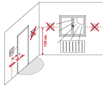
Proper thermostat placement

Button Functions
| Button | Function |
| ∧∨ | Increasing/decreasing temperature or value |
| <> | Selection of the operating mode, switching between values |
 |
Short press – selection confirmation Long press – entry to or exit from the menu |
| ∧+∨ | Long press causes blocking or unlocking the thermostat |
 |
Long press enters the installer mode |
LCD Icon description
![]()
| 1. current active mode 2. Comfort mode 3. Standard mode 4. Economic model 5. Automatic mode 6. PARTY mode 7. Holiday mode 8. Frost protection mode 9. Temperature unit 10. Manual mode/temp. override |
11. Current/set temperature 12. Program number 13. AM/PM 14. Keylock 15. Day of the week 16. Settings 17. Time 18. Additional temp. sensor 19. Cooling 20. Heating |
Installation
The VS30 thermostat has been designed for flush mounting in a standard electrical box with a diameter of 60 mm.
Note: Use the rear plate of the VS30 thermostat only with this model.
Wiring diagrams
VS30 thermostat in connection with actuator or pump An additional temperature sensor T is optional.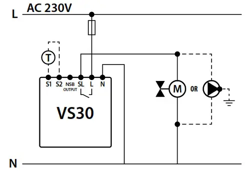
VS30 thermostat in connection with wiring center
In this diagram, the VS30 thermostat manages the NSB function, more details about NSB function can be found on the next page.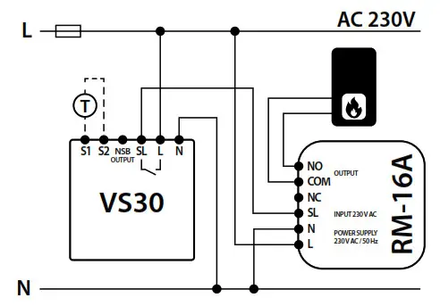
Note: In the KL06 wiring center, the SL terminal is marked with an arrow↓ icon.
VS30 thermostat in connection with a boiler with a “NO” voltage-free terminal through the RM-16A relay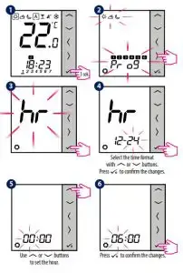
Time and date setting
Note: During the first start-up, the thermostat will automatically start time and date setting – in this case go to step 4.
Press any button to highlight the screen, then follow the steps below
7 Similarly to steps 5 and 6, set the minutes, year, month and day.
Temperature setting
Press any button to highlight the screen, then follow the steps below:
Manual mode – temperature settings
There are 4 temperature levels available. In manual mode, only one temperature level is active (icon in the frame indicates which mode is currently chosen). For each temperature levels, you can set a different temperature.
 |
– Comfort mode |
 |
– Standard mode |
 |
– Economic mode (when this mode is selected on the NSB output appears 230 V AC voltage) |
 |
– Frost protection mode. Usually used in a longer period of absence or during the holidays (available only in heating mode). |
The thermostat also has 2 additional modes:
– PARTY mode sets the comfort temperature for a defined time by the user (maximum 9 hours 50 minutes).
 |
– PARTY mode sets the comfort temperature for a defined time by theuser (maximum 9 hours 50 minutes). |
 |
– The HOLIDAY mode sets the frost protection temperature for a user defined period of time (maximum 99 days). |
Press any button to highlight the screen, then follow the steps below:
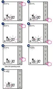
Programming
Press any button to highlight the screen, then follow the steps below:
Set the program start time:
Repeat steps 5 – 10 to set time and temperatures for next time ranges. No hour (–:–) on the display means whole day is planned already. The schedule can be divided into maximum 6-time ranges.
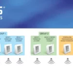
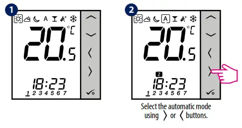
NSB function – automatic mode
The NSB (Night SetBack) function can automatically change temperatures on VS35 daily thermostats via VS30 programmable thermostat connected to a wiring center (or another external clock). NSB function switches between comfortable temperature and economic temperature.
To activate the automatic mode, select the A icon. On display together with the A icon, the controller indicates active temperature mode: or .
Note: For the NSB function to work, it is necessary to connect the wirings properly. Connection diagrams can be found on the previous page.
Press any button to highlight the screen, then follow the steps below:
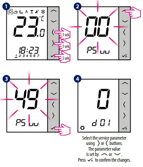
Installer settings
Press any button to highlight the screen, then follow the steps below:
Note: To restore the thermostat’s factory settings, in step 2 set the PSuu to 47 code, and confirm the selection with the button.
| dxx | Function | Value | Description | Default value |
| d01 | Control method temperature |
0 | PWM algorithm | 0 |
| 1 | Span ±0.25°C | |||
| 2 | Span ±0.5°C | |||
| d02 | Offset temperature | – from 3. 0°C to +3.0°C |
If the thermostat indicates wrong temperature, you can correct it by ± 3.0°C |
0°C |
| d03 | Using a floor tempera- ture sensor (51, S2) |
0 | No sensor | 0 |
| 1 | Sensor is connected | |||
| d04 | External sensor used for air or floor temperature measurement (Function is active, |
0 | Thermostat measures the temperature only on the external sensor |
0 |
| 1 | The sensor is used as protection against overheating the floor |
|||
| when d03=11 | ||||
| d05 | Cooling mode control method |
1 | Span ±0.5°C | 2 |
| 2 | Span ±1.0°C | |||
| d06 | Type of thermoelectric actuator |
0 | NO – normally open | 1 |
| 1 | NC – normally closed | |||
| d07 | Valve protection | 0 | OFF | 1 |
| 1 | ON | |||
| d08 | Frost protection temperature |
5-17°C | Frost protection / Holiday mode temperature |
5°C |
| d09 | (lock format | 0 | 12 hour | 1 |
| 1 | 24 hour | |||
| d11 | Daylight Saving fi me | 0 | OFF | 1 |
| 1 | ON | |||
| d 12 | Heating temperature limit |
5-35 ° C | The maximum heating temperature that can beset by the user |
35°C 35° |
| d13 | Cooling temperature limit |
5-40°C | The minimum cooling temperature that can be set by the user |
5°C |
| d14 | Maximum floor temperature (this function is active |
6-45°C | In order to protect the floor from overheating, heating will be turned OFF, when the maximum temp. of the floor sensor will be reached |
27°C |
| in heating mode when | ||||
| d04 =11 | ||||
| d15 | Minimum floor temperature (this function is active |
6-45°C | In order to protect the floor, heating will be turned ON, when the minimum temp. of the floor sensor will be reached |
10°C |
| in heating mode when | ||||
| d04 =1} | ||||
| d 16 | Lowerfloortemperature limit for cooling (this function is active | 6-45°C | In order to protect the floor, cooling will be tuned OFF, when the minimum temp. will be reached |
6°C |
| when d04 =11 | ||||
| d 17 | Choice of the default program |
1-5 | Selection 1 of the 5 default programs |
1 |
| d18 | Operating mode HEATING/COOLING |
0 | Heating system | 0 |
| 1 | Cooling system |
Error codes
| Error code | Description |
| Err02 | The maximum/minimum floor temperature has been exceeded |
| Err03 | The temperature sensor is faulty |
| Err04 | The temperature sensor is shorted |
![]() Relay module SALUS Controls
Relay module SALUS Controls
RM-16A
Relay module RM-16A opens and closes the circuit in order to affect the work of other devices. Some uses of the module RM-16A with other Salus products are shown below: 1. Connection of the thermostat with the high voltage relay 230V (e.g. VS30/RT200/ERT20/ERT30/ERT50/ VS10) with a gas boiler which requires free-voltage output NO/COM or NC/COM 2. Connection of the SALUS temperature regulator with the NO/COM relay (e.g. 091FL) with the boiler control which requires NC/COM output (NC/COM output is normally required in the solid fuel boiler controls ) 3. Connection of the receiver transmitting power higher than it is allowed by the relay in a regulator. The maximum electricity consumption of the receiver cannot exceed 16A 4. Connection of the devices other than electrothermal actuators with the wiring center ( KL06-M/ KL08NSB /KL08RF/KL10/KL10RF) e.g. if you want to connect a pump or an electric heating mat instead of an electrothermal actuator.
IMPORTER:
QL CONTROLS Sp. z o.o. Sp. k.
ul. Rolna 4, 43-262 Kobielice
PRODUCER:
Salus Limited
6/F, Building 20E, Phase 3, Hong Kong
Science Park, 20 Science Park East
Avenue, Shatin,
New Territories, Hong Kong

![]() Symbol meaning selecting electric electronic gear. Putting used gear with other waste products is strictly forbidden. The declaration of compliance is on www.salus-controls.pl site Made in Poland
Symbol meaning selecting electric electronic gear. Putting used gear with other waste products is strictly forbidden. The declaration of compliance is on www.salus-controls.pl site Made in Poland
 Relay module SALUS Controls Product code: RM-16A

The declaration of compliance is on www.salus-controls.pl site Made in Poland
www.salus-controls.eu
SAFETY INFORMATION
Before connecting the relay module with a different device make sure that its parameters are consistent with the RM-16A module specification. Incorrect connection may cause undesirable action, excessive overheating and combustion hazard. To avert the hazard make sure that the relay module RM-16A is correctly connected. The connection of the device can be done only by a qualified installer who has up-to-date eligibility.
INTRODUCTION
Relay module RM-16A opens and closes the circuit in order to affect the work of other devices. Some uses of the module RM-16A with other Salus products are shown below:
- Connection of the thermostat with the voltage relay 230V (e.g. VS30/RT200/ERT20/ ERT30/ERT50/VS10) with a gas-fired boiler which requires free-voltage output NO/COM or NC/COM
- Connection of the SALUS thermostat with the NO/COM relay (e.g. 091FL) with the boiler control which needs NC/COM output (NC/COM output is normally required in the solid fuel boiler controls)
- Connection of the receiver transmitting power higher than it is allowed by the relay in a regulator. The maximum electricity consumption of the receiver cannot exceed 16A 4. Connection of the devices other than electrothermal actuators with the wiring center ( KL06-M/KL08NSB /KL08RF/KL10/KL10RF) e.g. if you want to connect a pump or an electric heating mat instead of a electrothermal actuator.
PRODUCT SPECIFICATION
| Power: | 16A / 250V AC, 4000VA |
| INPUT NO/COM: | Connection of a regulator with the free voltage relay NO/COM |
| OUTPUT NC/COM/NO: | Output receiver |
| INPUT SL: | Connection of the regulator with the voltage relay 230V |
| POWER SUPPLY N/L: | Power of 230V AC/50Hz |
| Measurements: | 47x47x21 |
VISUAL ASPECT

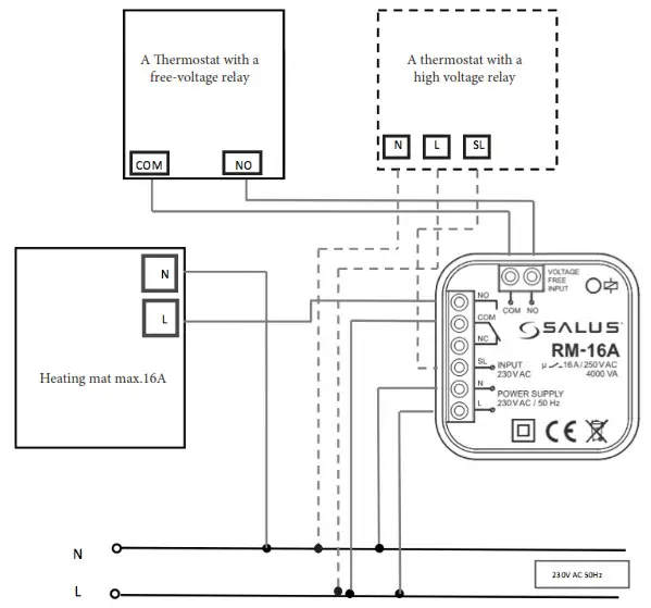
CONNECTION DIAGRAMS
- Connection of the thermostat with a voltage relay 230V (e.g. VS30/RT200/ERT20/ERT30/ ERT50/VS10) to a gas boiler which requires free-voltage output NO/COM.

- Connection of the SALUS temperature regulator with NO/COM relay (e.g. 091FL) with a boiler control which requires NC/COM output ( NC/COM output is normally required in solid fuel boilers controls).

- Connection of the receiver transmitting power higher than it is allowed by the relay in a regulator. The maximum electricity consumption of the receiver cannot exceed 16A

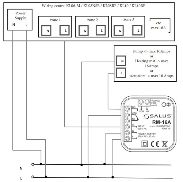
- Connection of the devices other than electrothermal actuators with the wiring center ( KL06-M / KL08NSB / KL08RF / KL10 / KL10RF) e.g. if you want to connect a pump or an electric heating mat instead of an electrothermal actuator.