Schneider S1B33894 QO and Homeline Load Centers

Safety Information
This bulletin contains instructions for the installation and operation of QO and Homeline load centers. It also includes installation instructions for standard and tandem branch circuit breakers. See separate instruction bulletins included with advanced function circuit breakers and accessories, when installed.
DANGER
HAZARD OF ELECTRIC SHOCK, EXPLOSION, OR ARC FLASH
- Apply appropriate personal protective equipment (PPE) and follow safe electrical work practices. See NFPA 70E, NOM-029-STPS or CSA Z462 or local equivalent.
- This equipment must only be installed and serviced by qualified electrical personnel.
- Turn off all power supplying this equipment before working on or inside equipment.
- Always use a properly rated voltage sensing device to confirm power is off.
- Replace all devices, doors and covers before turning on power to this equipment.
- Do not allow petroleum-based paints, solvents, or sprays to contact the nonmetallic parts of this product.
- Before starting a wiring installation or addition, consult a local building or electrical inspector for current National Electrical Code requirements. Local codes vary, but are adopted and enforced to promote safe electrical installations. A permit may be needed to do electrical work, and some codes may require an inspection of the electrical work.
- This equipment may not be suitable for use in corrosive environments present in agricultural buildings. See NEC 547.
Failure to follow these instructions will result in death or serious injury.
Preparation
- Determine the wiring or conduit requirements for the main and branch circuits, as required by local electrical codes.
- Select the proper cable clamp, or use other approved methods for securing the cable or conduit to the enclosure.
- Remove the appropriate knockouts required for installation of cable clamps or conduit (Table 1). To remove the knockouts, see Figure 1.
Table 1: Bolt-on Conduit Hubs for Outdoor Load Centers
| Conduit | Hub No. |
| 3/4 in. | B-075 |
| 1 in. | B-100 |
| 1-1/4 in. | B-125 |
| 1-1/2 in. | B-150 |
| 2 in. | B-200 |
| 2-1/2 in. | B-250 |
Figure 1: Removing Knockouts
Enclosure Mounting
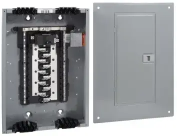
Surface Mounting (Indoor and Outdoor) Secure the enclosure to the wall with appropriate fasteners. Use all pre-cut holes in the back of the enclosure for mounting. See Figure 2.
Outdoor
- Use the sealing gaskets provided if the mounting knockout locations shown in Figure 2 are used.
- Use either one mounting hole at the top and two mounting holes at the bottom, or two mounting knockout holes at the top and two mounting holes at the bottom. See Figure 2.
Surface Mounting Temporarily position the enclosure with the centered tear drop hole. Secure the enclosure to the wall using the four mounting holes. Figure 2: Surface Mounting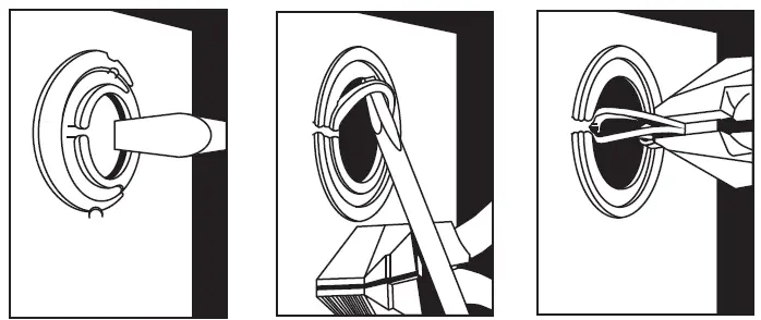
Flush Mounting (Indoor Enclosure Only
- Remove the four small mounting knockouts on the side walls for securing to sixteen inch stud walls. See Figure 3.
- Position the enclosure between studs so that the front edge is flush with the finished wall.
- Secure the enclosure to the studs through the small knockouts. See Figure 3C.
Figure 3: Flush Mounting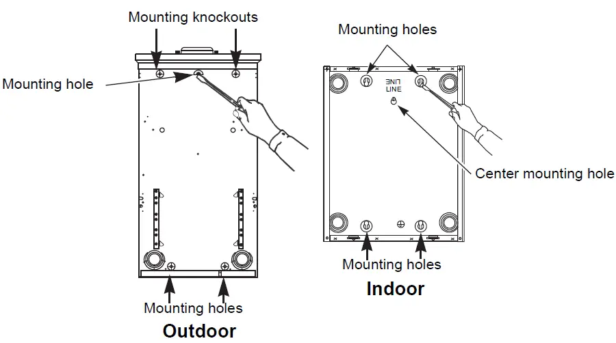
Main Circuit Breaker or Main Lug Wiring
- Pull the conductors into the enclosure. Use approved wire clamps, conduit bushings, or other approved methods to secure the conductor to the enclosure and prevent damage to the conductor insulation.
- Connect the main and neutral wires.
- Install the main and neutral wires according to the wiring diagram on the load center.
- Connect the service ground, equipment grounding wire, or both as required by the local electrical code.
- Torque each connection to the value specified on the load center wiring diagram attached to the enclosure.
- If required by the local code, install the enclosed green neutral bonding screw through the hole in the neutral bar. Thread the screw into the hole in the enclosure and torque to the value specified on the card shipped with the bonding screw.
Branch Circuit Breaker Installation and Removal
WARNING HAZARD OF PERSONAL INJURY OR EQUIPMENT DAMAGE This equipment is designed and tested by Schneider Electric™ to performance levels which meet Underwriter’s Laboratories® (UL®) standards and Mexican Official Standards (NOM) listing. Use only Square D™ brand circuit breakers and accessories. Failure to follow these instructions can result in death or serious injury.
NOTE: See separate instruction bulletins included with advanced function circuit breakers and accessories for their installation. QOP type circuit breakers are only acceptable for use on QO plug-on neutral load centers.
Standard and Tandem Branch Circuit Breakers—Installation
NOTE: Install QOT and HOMT tandem-type circuit breakers only in single-phase load centers marked for use with tandem circuit breakers. Refer to the wiring diagram on the load center for the installation location.
- Determine the wiring or conduit requirements for the branch circuit.
- Turn OFF (O) the circuit breaker.
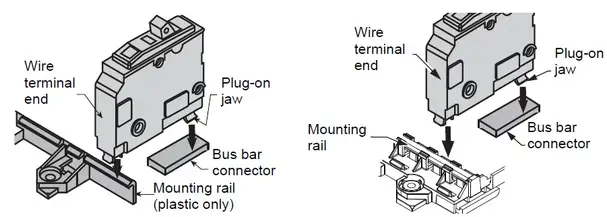
NOTE: For QOT CTL tandem only: hold the circuit breaker at 30–45° angle. - Install the wire terminal end of the circuit breaker onto the mounting rail.
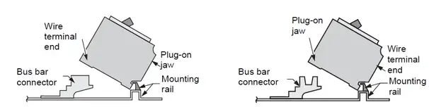
- Rotate the circuit breaker inward until the plug-on jaw fully engages the bus bar connector. Keep the bottom of the circuit breaker’s case against the mounting rail. Check the terminal end of the circuit breaker for engagement to the mounting rail.
- Remove the wire insulation from the branch wire as required. Install the branch wire into the load terminal of the branch circuit breaker.
- Torque each branch circuit breaker connection to the value specified on the circuit breaker.
- Torque each neutral and ground connection to the value specified on the load center wiring diagram attached to the enclosure.
Figure 4: QO Standard Circuit Breaker Figure 5: QO Tandem Circuit Breaker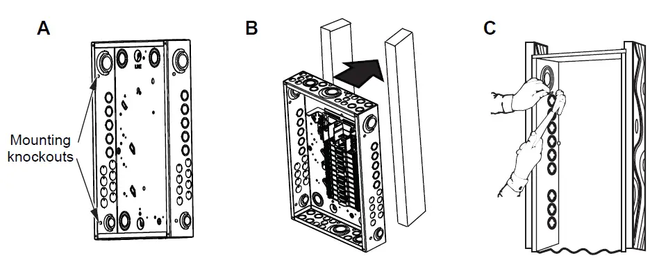
NOTE: Non-class CTL tandem circuit breaker shown. QOT class CTL tandem circuit breaker (not shown) cannot be installed on a plug-on neutral load center (metal mounting rail).
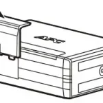
Figure 6: Homeline Standard Circuit Breaker Figure 7: Homeline Tandem Circuit Breaker
Removal
- Turn OFF (O) the circuit breaker. Remove the wires.
- To disconnect the plug-on jaw from the connector and mounting rail, lift the plug-on end of the circuit breaker until the circuit breaker jaw disconnects from the bus bar. Continue lifting until the terminal end disengages from the mounting rail. See Figure 4, 5, or 6 depending on circuit breaker type.
Installing the Cover / Trim
- Remove the cover twistouts. Remove the appropriate twistouts to match the number of circuit breakers being installed. See Figure 8.
- Attach the Spanish translation label, supplied with the load center, to the inside of the door or cover. See Figure 9.
- Identify the circuit breakers on the directory label.
- For service equipment, apply the “Service Disconnect” label(s) near the disconnect handle(s). If the main circuit breaker is installed and the device is used as a branch panel, apply the “Main” label to the trim near the main circuit breaker handle. See Figure 9.
- Install the trim/cover using the screws provided and torque to 20 lbs-in. (2.3 N•m).
- For QO outdoor load centers that are 150–225 A single-phase, main lug devices rated for 22,000 RMS symmetrical amperes short circuit systems, use four screws by removing the interior trim support bracket knockout. See Figure 9.
- Fill any unused circuit breaker opening with the filler plates.
- Figure 8: Remove Twistouts
- Figure 9: Label Locations
Energizing the Load Center
- Before energizing the load center, turn off the main and all branch circuit breakers.
- After power is turned on to the load center, turn on the main circuit breaker and then turn on the branch circuit breakers.
- Rotate the door latch counterclockwise to allow engagement through the door slot (outdoor only).
- Close the door until secured by the latch.
Schneider Electric USA, Inc. 800 Federal Street Andover, MA 01810 USA 1-888-778-2733 www.se.com/us Electrical equipment should be installed, operated, serviced, and maintained only by qualified personnel. No responsibility is assumed by Schneider Electric for any consequences arising out of the use of this material. Schneider Electric and Square D are trademarks owned by Schneider Electric Industries SAS or its affiliated companies. All other trademarks are the property of their respective owners. © 2012–2021 Schneider Electric All Rights Reserved