Range Extender
 Setup with videos
Scan the QR code, or visit
https://www.tp-link.com/download/TL-WA854RE.html
 https://www.tp-link.com/download/TL-WA854RE.html
* Images may differ from your actual product.
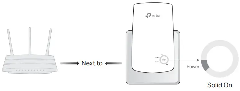
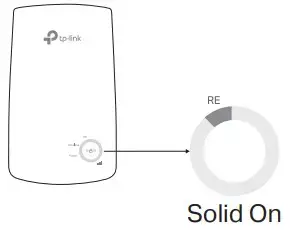
Power On
Plug the extender into a power outlet next to your router. Wait until its Power LED turns solid on.
Note: For safety, only plug the extender in the direction as shown below.

Set-Up
Via the Tether App
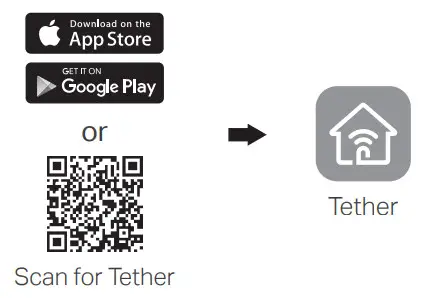
- Get the up-to-date Tether app from the Apple App Store or Google Play, or simply scan the QR code.
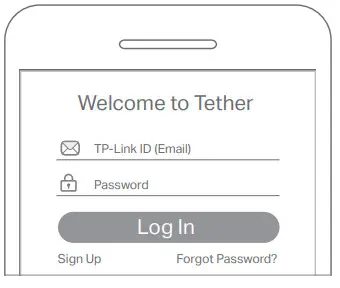
- Launch the Tether app and log in with your TP-Link ID. If you don’t have an account, create one first.
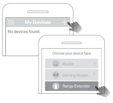
- Tap the button and select Range Extender.
Note: If you cannot find your device, please refer to FAQ > Q1.
- Follow app instructions to complete the setup.
The RE LED should turn solid on, indicating a successful connection to your router.
Note: If the LED does not turn solid on, please refer to FAQ > Q2.
More Setup Methods
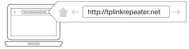
Via a Web Browser
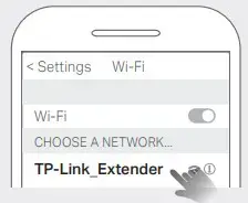
- Connect your computer or smartphone to the extender’s network TP-Link_Extender.
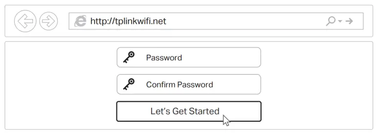
- Visit http://tplinkrepeater.net or http://192.168.0.254 in a web browser. Create a password to log in.
- Follow web instructions to complete the setup.
Via the WPS Button
- Press the WPS button on your router.
- Within 2 minutes, press the WPS button on the extender for 1 second. The RE LED should change from blinking to solid on, indicating a successful connection.
Extended Network Name:
Router’s network name with _EXT at the end
Password: Same as your router
For more details, please refer to the user guide at https://www.tp-link.com/support/download/.
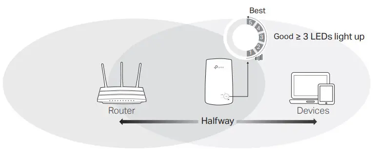
Relocate
- Plugin the extender about halfway between your router and the Wi-Fi dead zone. The location you choose must be within the range of your router.
- Wait for about 2 minutes until the 3 or more LEDs light up. If not, relocate the extender closer to the router to achieve better signal quality.
Tip: To place the extender for optimal Wi-Fi performance, access extender settings via the Tether app and go to Tools > Location Assistant, or simply scan the QR code to visit https://www.tp-link.com/support/faq/3103/.
https://www.tp-link.com/support/faq/3103/

 Enjoy the internet!
Access Extender Settings
After setup, you can access extender settings via any of the methods below. You can reselect the host networks, change extended network settings, and more.
Note: If your extender and router use the same network name, Method 1 is recommended.
Method 1: Via the Tether App

- Connect your smartphone to the extender‘s or router’s network.
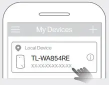
- Launch the Tether app, select your extender, and log in.
- View or change extender settings as needed.
Method 2: Via a Web Browser
- Connect your computer or smartphone to the extender’s network. If you are using a computer, unplug the Ethernet cable if any.
- Launch a web browser, enter http://tplinkrepeater.net in the address bar, and log in.
- View or change extender settings as needed.
LED Explanation
| LED | Status | Indication |
| RE | On/Off Blinking |
The extender is connected or not connected to your router’s wireless network. WPS connection is in progress. |
| Wireless | On/Off | The extender’s wireless function is enabled or disabled. |
| Power | On/Off Blinking | The extender is on or off. The system is starting up or a firmware upgrade is in progress. |
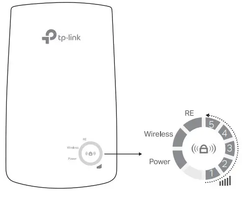 (Signal Strength) (Signal Strength) |
On/Off | Indicates the Wi-Fi connection between the extender and the router. More lit LEDs indicate better signal strength. |
FAQ (Frequently Asked Questions)
Q1. What should I do if the Tether app cannot find my device during setup?
Try another method by following the steps below:
- Connect your smartphone to the extender’s network TP-Link_Extender.

- Launch the Tether app, and select your extender.
Tip: If you have connected to the extender’s Wi-Fi but still cannot find your device, try turning off your cellular data.
- Follow app instructions to complete the setup.
If you are still having problems, contact our technical support.
Q2. What should I do if the RE LED doesn’t turn solid on after completing the setup via the Tether app or web browser?
- You may have entered an incorrect Wi-Fi password for your host router during the configuration. Check the password and try again.
- Make sure the extender is close to your router, preferably within 16 feet, and away from large electrical appliances.
- If you have enabled wireless MAC filtering, wireless access control, or access control list (ACL) on your router, disable them first, then follow any method on the front page to complete the configuration.
- Try setting it up via the WPS button.
- Reset the extender and go through the configuration again.
If you are still having problems, contact our technical support.
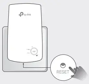
Q3. How do I reset the extender?
- With the extender powered on, use a pin to press the RESET button for 1 second. The extender will reboot.
If you need more setup help, please visit https://www.tp-link.com/support/faq/3074/, or simply scan the QR code.
https://www.tp-link.com/support/faq/3074/
Safety Information

- Keep the device away from water, fire, humidity or hot environments.
- Do not attempt to disassemble, repair, or modify the device. If you need service, please contact us.
- Do not use the device where wireless devices are not allowed.
- The socket outlet shall be installed near the equipment and shall be easily accessible.
Please read and follow the above safety information when operating the device. We cannot guarantee that no accidents or damage will occur due to improper use of the device. Please use this product with care and operate at your own risk.
TP-Link hereby declares that the device is in compliance with the essential requirements and other relevant provisions of directives 2014/53/EU, 2009/125/EC, 2011 /65/EU, and (EU) 2015/863. The original EU Declaration of Conformity may be found at https://www.tp-link.com/en/support/ce TP-Link hereby declares that the device is in compliance with the essential requirements and other relevant provisions of the Radio Equipment Regulations 2017.
The original UK Declaration of Conformity may be found at https://www.tp-link.com/support/ukca
 To communicate with TP-Link users or engineers, please join the TP-Link Community at https://community.tp-link.com.
 If you have any suggestions or needs for our product guides, you are welcome to email [email protected].
 For technical support, replacement services, user manuals, and other information, please visit https://www.tp-link.com/support, or simply scan the QR code.

http://www.tp-link.com/support
300Mbps Wi-Fi Range Extender Model: TL-WA854RE
]]>TL-PA8010P AV1300 Gigabit Passthrough Powerline Adapter
User GuideUser Guide
AV1300 Gigabit Passthrough
Powerline Adapter
TL-PA8010P
About This Guide
This guide is a complement to Quick Installation Guide. The Quick Installation Guide provides instructions for quick internet setup, while this guide contains details of each
function and demonstrates how to configure them in typical scenarios.
When using this guide, please notice that features of the powerline adapter may vary slightly depending on the model and software version you have. The powerline adapter availability may also vary by region or ISP. All images, steps, and descriptions in this guide are only examples and may not reflect your actual powerline adapter experience.
*Compatible with all HomePlug AV and AV2 Standard Powerline adapters. This product may not be compatible with routers or gateways with firmware that has been altered, is based on open source programs, or are non-standard or outdated.
*Maximum wireless signal rates are the physical rates derived from IEEE Standard 802.11 specifications. Actual wireless data throughput and wireless coverage are not guaranteed and will vary as a result of network conditions, client limitations, and environmental factors, including building materials, obstacles, volume and density of traffic, and client location.
*Maximum Powerline signal rates are the physical rates derived from HomeplugAV/AV2 specifications.
Actual Powerline data throughput and Powerline range are not guaranteed and will vary as a result of network conditions and environmental factors, including electrical interference, volume of traffic and network overhead, AFCI circuit breaker, and Powerline being located in a separate circuit.
Conventions
In this guide, the following conventions are used:
| Convention | Description |
| Teal Underlined | Hyperlinks are in teal and underlined. You can click to redirect to a website or a specific section. |
| Teal | Key information appears in teal, including management page text such as menus, items, buttons and so on. |
 Note: Note: |
Ignoring this type of note might result in a malfunction or damage to the device. |
| Tips: |
Indicates important information that helps you make better use of your device. |
More Info
- The latest software, management app and utility are available from the Download Center at https://www.tp-link.com/support/.
- The Quick Installation Guide (QIG) can be found where you find this guide or inside the product package.
- Specifications can be found on the product page at https://www.tp-link.com.
- A community is provided for you to discuss our products at https://community.tp-link.com/.
- Our Technical Support contact information can be found at the Contact Technical Support page at https://www.tp-link.com/support/.
Chapter 1 Get to Know Your Powerline Adapter
This chapter introduces what the powerline adapter can do and describes its appearance.
It contains the following sections:
- Product Overview
- Product Appearance
1. 1 Product Overview
TP-Link powerline adapter aims to extend your existing home network, with the help of your home’s electrical circuit.
The integrated power socket on the powerline adapter provides an outlet for other electronic devices. Its built-in noise filter eliminates electrical signal noise and therefore guarantees the high quality transmission of data via powerline.
1.2 Product Appearance
Your powerline adapter may differ in appearance slightly from that depicted because of the region and product version.
Note: TL-PA8010P KIT (European version) is used for demonstration in this guide
1.2.1 LED LegendLEDs indicate the powerline adapter’s working status. For more details, please refer to the following table.
| Name | Status | Indication |
| Power |
On/Off | The powerline adapter is on or off. |
| Blinking | Blinking quickly: Pairing is in process. | |
| Blinking slowly: Power-Saving Mode* is on. | ||
| On | The powerline adapter is successfully connected to a powerline network. | |
| Off | The powerline adapter is not connected to any powerline network. | |
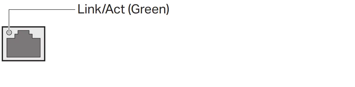
| Ethernet | On | The Ethernet port is connected. |
| Off | The Ethernet port is not connected. |

* Five minutes after the device connected to the powerline adapter is turned off or inactive, the powerline adapter will automatically switch to Power-Saving Mode.
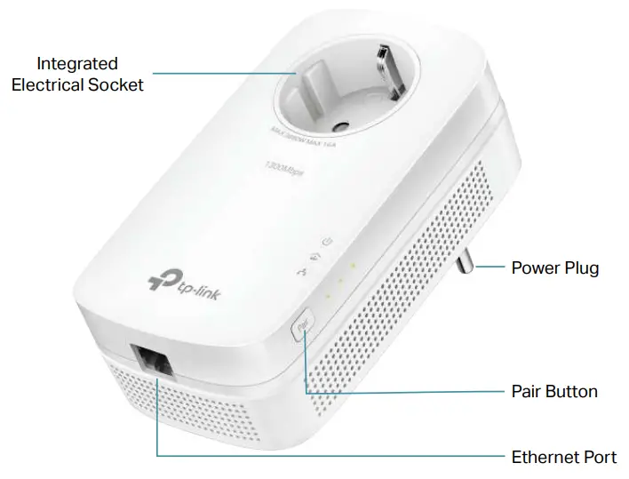
1 .2 .2 Physical InterfaceIntegrated Electrical Socket
Used as an electrical outlet expansion for power strip or household appliances. It can remove some electrical noise that might affect powerline performance.
Power Plug
The powerline adapter has a Plug that can be connected to a (100V-240V~, 50/60Hz) power socket.
Pair Button
Press and hold the button for 1 second to join a powerline network. Go to Secure Your Powerline Network by Pairing for more information.
Press and hold for more than 6 seconds to reset the powerline adapter.
Ethernet Port
Connect the Ethernet port to your wired devices, such as a computer, a router or a game console, via an Ethernet cable.
Chapter 2 Use Your Powerline Adapter
This chapter guides you on how to use the powerline adapter.
It contains the following sections:
- Before You Start
- Extend Your Wired Network by Plug & Play
- Secure Your Powerline Network by Pairing
- Add Another Powerline Adapter
- Manage Your Powerline Network via tpPLC Utility
2 .1 Before You Start
Powerline adapters work in pairs. You should have at least two powerline products to build a powerline network. To optimize your network performance, please follow these
principles:
- All powerline adapters should be on the same electrical wiring system.
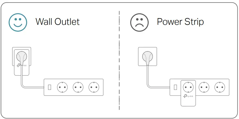
- Avoid plugging in powerline adapters and high-powered household devices (such as washing machines and refrigerators) close to one another.
- Plug the powerline adapter directly into a wall outlet. Do not plug the powerline adapter into a power strip, extension cord, or surge protector.
- Use the powerline adapter only in below directions.
- Environment:
Operating Temperature: 0 ºC ~ 40 ºC (32°F ~ 104°F )
Storage Temperature: -20°C~70°C (-4°F~158°F)
Operating Humidity: 10%~90%RH, Non-condensing
Storage Humidity: 5%~90%RH, Non-condensing
2 2 Extend Your Wired Network by Plug & Play
I want to:
Use two powerline adapters to set up a new powerline network in my house.
For example, I have a router in my house, but there are not enough LAN ports for all my wired devices. I don’t want complex and expensive cabling. People told me that I can solve this problem with two powerline adapters.
How can I do that?
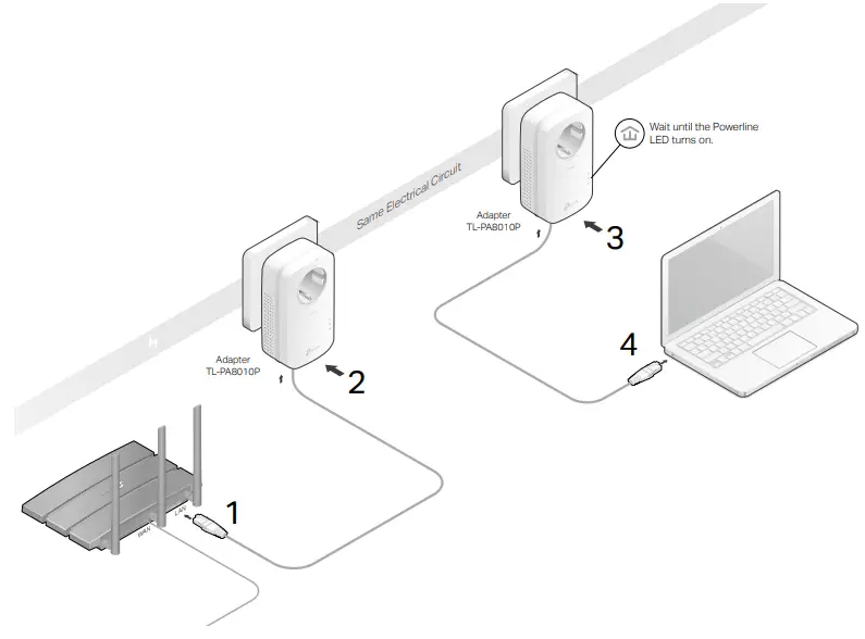
- Connect one of the powerline adapters to an available LAN port of the router using an Ethernet cable.
- Plug the powerline adapter into a wall outlet.
- Plug the other powerline adapter into a wall outlet on the same electrical circuit at the place you want internet. Wait until the powerline LED
 turns on.
Note: If the Powerline LED does not turn on, reset each powerline adapter to its factory default settings.
Refer to FAQ-Q2 for detailed information. - Connect your wired device, such as a computer or game console, to the powerline adapter via an Ethernet cable.
Done!
Now enjoy the internet!
2 3 Secure Your Powerline Network by Pairing
All powerline adapters share some common factory settings, and can communicate with one another. If you want your powerline adapters to communicate only with your own powerline adapters, you should pair them. Thus a secured powerline network is formed and other powerline adapters can no longer join your powerline network without
being paired.
Note: You can only pair two devices at a time.
I want to:
Secure my powerline network and prevent other powerline devices from being added to my network.
For example, I’ve extended my network using the Plug & Play method. Now I want to secure my network.
How can I do that?
- Verify all powerline devices’ Power LEDs are solid on.
Tips: We recommend that you plug in your powerline devices next to each other, or as close to each other as possible when pairing. Your settings will not be affected. The devices can be relocated to where they are needed once pairing is complete. - Press the Pair button on any of the powerline devices for 1 second. Its Power LED should start blinking. Login and Reset Instructions
- (Within 2 minutes) Press the Pair button on another device for 1 second. Its Power LED should start blinking. When the Powerline LED lights up, a powerline network has been successfully created.

Done!
Enjoy your secure powerline network!
2.4 Add Another Powerline Adapter
I want to:
Add a new powerline adapter into the existing powerline network to extend my network.
For example, I’ve already set up a powerline network using powerline devices, but the network does not reach everywhere I need it to. I purchased another one to further extend my network.
How can I do that?
- Plug the new powerline adapter into a wall outlet near one of the existing powerline devices.

- Press the Pair button on any of the existing powerline devices for 1 second. Its Power LED starts blinking.
- Within 2 minutes, press the Pair button on the new powerline adapter for 1 second. Its Power LED starts blinking.

- When the Powerline LED turns on, it’s done. Relocate the new powerline adapter to the place where wired internet access is needed.

Done!
Enjoy the internet through your extended network!
2.5 Manage Your Powerline Network via tpPLC Utility
The tpPLC utility enables you to view and manage your TP-Link powerline network. Its bold and intuitive interface helps you easily configure each powerline device.
You can find the utility and its user guide on the product support page at https://www.tp-link.com.
FAQ (Frequently Asked Questions)
Q1 How do I reset my powerline adapter?
– With the powerline adapter plugged into the wall socket, press and hold its Pair button for more than 6 seconds until the Power LED goes off momentarily and comes back on.
Q2 What should I do if the Powerline LED is off?
– Try another wall socket and make sure all powerline devices are on the same electrical circuit.
– Try to set up a powerline network by pairing. Refer to Secure Your Powerline Network by Pairing for instructions.
– If the problem persists, contact our Technical Support.
Q3 What should I do if there is no internet connection in my powerline network?
– Make sure all powerline devices are on the same electrical circuit.
– Make sure the Powerline LEDs are lit on all of your powerline devices. If they are not, pair all powerline devices according to Secure Your Powerline Network by Pairing.
– Make sure all devices are correctly and securely connected.
– Verify that you have an internet connection by connecting your computer directly to the modem or the router.
Q4 What should I do if a successfully-paired powerline device does not reconnect after it is relocated?
– Try another socket on the same electrical circuit.
– Try to pair the device again, and make sure the Powerline LED is on.
– Check for possible interference due to a washing machine, air conditioner or other household appliance that may be too close to one of the powerline devices. Plug the
appliance into the integrated electrical socket to remove the electrical noise if your powerline device has an integrated electrical socket.
COPYRIGHT & TRADEMARKS
Specifications are subject to change without notice. ![]() is a registered trademark of TP-Link Technologies Co., Ltd. Other brands and product names are trademarks or registered trademarks of their respective holders.
is a registered trademark of TP-Link Technologies Co., Ltd. Other brands and product names are trademarks or registered trademarks of their respective holders.
No part of the specifications may be reproduced in any form or by any means or used to make any derivative such as translation, transformation, or adaptation without permission from TP-Link Technologies Co., Ltd. Copyright © 2019 TP-Link Technologies Co., Ltd. All rights reserved.
FCC compliance information statement
Product Name: AV1300 Gigabit Passthrough Powerline Adapter
Model Number: TL-PA8010P
Responsible party:
TP-Link USA Corporation, d/b/a TP-Link North America, Inc
Address: 145 South State College Blvd. Suite 400, Brea, CA 92821
Website: http://www.tp-link.com/us/
Tel: +1 626 333 0234
Fax: +1 909 527 6803
E-mail: [email protected]
This equipment has been tested and found to comply with the limits for a Class B digital device, pursuant to part 15 of the FCC Rules. These limits are designed to provide reasonable protection against harmful interference in a residential installation. This equipment generates, uses and can radiate radio frequency energy and, if not installed and used in accordance with the instructions, may cause harmful interference to radio communications. However, there is no guarantee that interference will not occur in a particular installation. If this equipment does cause harmful interference to radio or television reception, which can be determined by turning the equipment off and on, the
user is encouraged to try to correct the interference by one or more of the following measures:
- Reorient or relocate the receiving antenna.
- Increase the separation between the equipment and receiver.
- Connect the equipment into an outlet on a circuit different from that to which the receiver is connected.
- Consult the dealer or an experienced radio/ TV technician for help.
This device complies with part 15 of the FCC Rules. Operation is subject to the following two conditions:
- This device may not cause harmful interference.
- This device must accept any interference received, including interference that may cause undesired operation.
Any changes or modifications not expressly approved by the party responsible for compliance could void the user’s authority to operate the equipment.
We, TP-Link USA Corporation, has determined that the equipment shown as above has been shown to comply with the applicable technical standards, FCC part 15. There is no unauthorized change is made in the equipment and the equipment is properly maintained and operated.
Issue Date: 2019.08.19
CE Mark Warning
This is a class B product. In a domestic environment, this product may cause radio interference, in which case the user may be required to take adequate measures.
EU Declaration of Conformity
TP-Link hereby declares that the device is in compliance with the essential requirements and other relevant provisions of directives 2014/30/EU, 2014/35/EU, 2009/125/EC, 2011/65/EU and (EU)2015/863.
The original EU declaration of conformity may be found at https://www.tp-link.com/en/ce Canadian Compliance Statement
This device contains licence-exempt transmitter(s)/receiver(s) that comply with Innovation, Science and Economic Development Canada’s licence-exempt RSS(s).
Operation is subject to the following two conditions:
- This device may not cause interference
- This device must accept any interference, including interference that may cause undesired operation of the device.
Industry Canada Statement
CAN ICES-3 (B)/NMB-3(B)
CAN ICES-6/NMB-6
Korea Warning Statements
- Keep the device away from water, fire, humidity or hot environments.
- Do not attempt to disassemble, repair, or modify the device.
- Do not use damaged charger or USB cable to charge the device.
- The socket-outlet shall be installed near the equipment and shall be easily accessible
- For passthrough devices, plug the power strips into the integrated electrical
 sockets of the devices,but devices of the same or another type not be stacked in normal use.
 - Plug the powerline devices directly into the wall outlets but not the power strips.
- Plug the powerline devices into the wall outlets with earthing connection.
Please read and follow the above safety information when operating the device. We cannot guarantee that no accidents or damage will occur due to improper use of the device. Please use this product with care and operate at your own risk.
![]() CAUTION: Double pole, neutral fusing. Disconnect mains before servicing.
CAUTION: Double pole, neutral fusing. Disconnect mains before servicing.
Explanation of the symbols on the product label
| Symbol | Explanation |
 |
AC voltage |
|
DC voltage |
| Indoor use only | |
| Functional earth wiring terminals only | |
| Warning electric shock | |
| Fuse is used in neutral N | |
 |
RECYCLING This product bears the selective sorting symbol for Waste electrical and electronic equipment (WEEE). This means that this product must be handled pursuant to European directive 2012/19/EU in order to be recycled or dismantled to minimize its impact on the environment. User has the choice to give his product to a competent recycling organization or to the retailer when he buys a new electrical or electronic equipment. |
LED Explanation
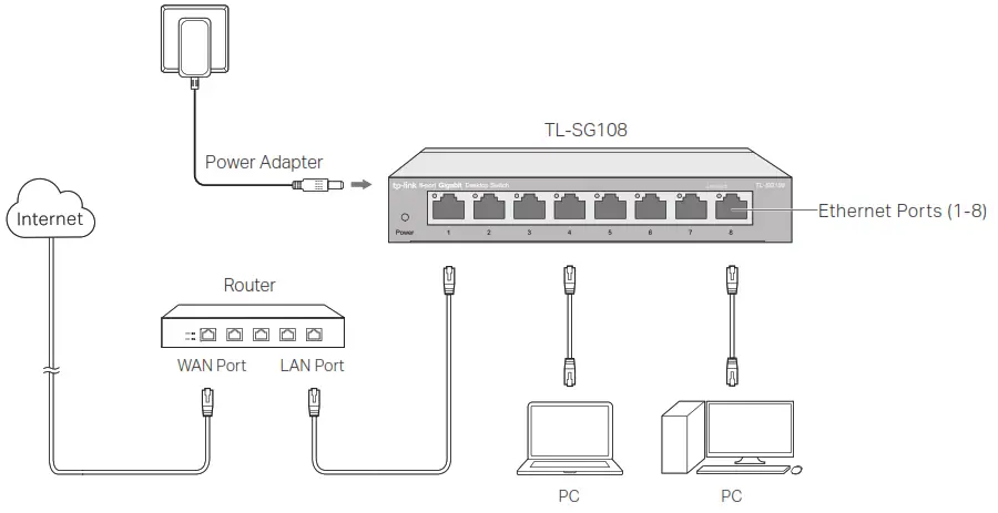
 Power
Power
On: Power on
Off: Power off
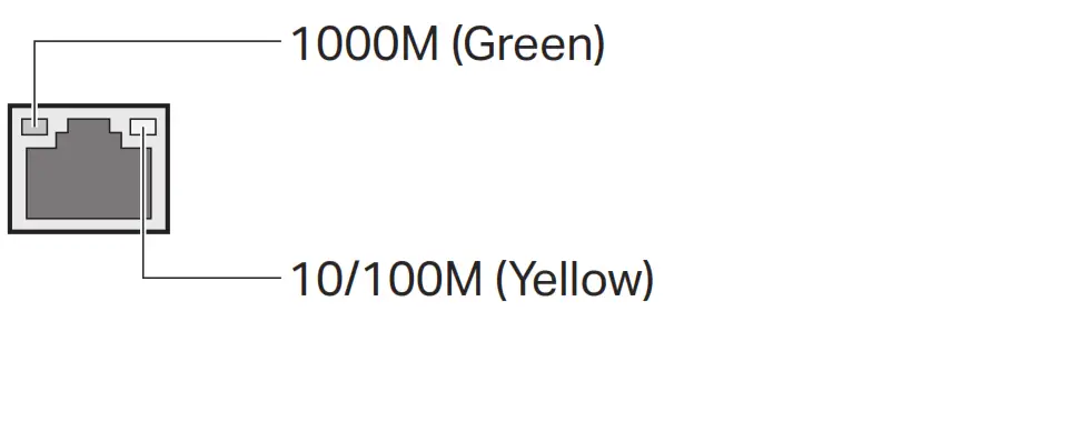
Link/Act (For TL-SG105/TL-SG105S/TL-SG108/TL-SG108S)
 On: Running at 10/100/1000 Mbps
Flashing: Transmitting/receiving data
Off: No device is linked to the corresponding port
Link/Act (For TL-SG116)
On: Running at 1000 Mbps
Flashing: Transmitting/receiving data
 On: Running at 10/100 Mbps
Flashing: Transmitting/receiving data
Note:
For simplicity, we will take TL-SG108 for example throughout this Guide.
Connection
Specifications
General Specifications
| Standard | IEEE802.3, IEEE802.31. IEEE802.3u. IEEE802.3ab, IEEE802.3x. IEEE802.1p |
| Protocol | CSMA/CD |
| Data Transfer Rate | Ethernet: 10 Mbps (Half Duplex). 20 Mbps (Full Duplex) Fast Ethernet: 100 Mbps (Half Duplex). 200 Mbps (Full Duplex) Gigabit Ethernet: 2000 Mbps (Full Duplex) |
| Network Media (Cable) | 10Base-T: UTP category 3. 4. 5 cable (maximum 100 m) EIAMA-568 100 0 STP (maximum 100 m) 100Base-TX: UTP category 5. 5e cable (maximum 100 m) EIAMA-568 100 0 STP (maximum 100 m) 1000Base-T: UTP Category 5e cable (maximum 100 m) EIN11A-568 100 Q STP (maximum 100 m) |
| Interface | 5/8/16 10/100/1000 Mbps Auto-Negotiation RJ45 Ports |
| LED Indicators | Power. Link/Act LED |
| Advanced Features | IGMP Snooping. QoS (802.1p/DSCP Priority) |
| Transfer Method | Store-and-Forward |
| MAC Address Learning | Automatically learning, automatically aging |
| Frame Forward Rate | 10Base-T: 14881 pps/Port 100Base-TX: 148810pps/Port 1000Base-T: 1488095pps/Port |
| Wall Mountable | Yes |
| Distance Between Mounting Holes | TL-SG105/TL-SG105S: 39 mm TL-SG108/TL-SG1085: 94 mm TL-SG116: 200 mm |
Environmental and Physical Specifications
| Operating Temperature | 0 ˚C to 40 ˚C (32 ˚F to 104 ˚F) |
| Storage Temperature | -40 ˚C to 70 ˚C (-40 ˚F to 158 ˚F) |
| Operating Humidity | 10% to 90%RH non-condensing |
| Storage Humidity | 5% to 90%RH non-condensing |
Safety Information
- Keep the device away from water, fire, humidity, or hot environments.
- Do not attempt to disassemble, repair, or modify the device. If you need service, please contact us.
- Do not use a damaged charger or USB cable to charge the device.
- Do not use any other chargers than those recommended.
- The adapter shall be installed near the equipment and shall be easily accessible.
- Use only power supplies which are provided by the manufacturer and in the original packing of this product. If you have any questions, please don’t hesitate to contact us.
Frequently Asked Questions (FAQ)
Q1. The Power LED is not lit.
The Power LED should be lit when the power system is working normally. If the Power LED is not lit, check as follows:
A1: Make sure the power adapter is connected to the switch with the power source properly.
A2: Make sure the voltage of the power supply meets the requirements of the input voltage of the switch.
A3: Make sure the power source is ON.
Q2. The Link/Act LED is not lit when a device is connected to the corresponding port.
It is recommended that you check the following items:
A1: Make sure that the cable connectors are firmly plugged into the switch and the device.
A2: Make sure the connected device is turned on and works normally.
A3: The cable must be less than 100 meters long (328 feet).
 To ask questions, find answers, and communicate with TP-Link users or engineers, please visit https://community.tp-link.com to join TP-Link Community.
 For technical support and other information, please visit https://www.tp-link.com/support, or simply scan the QR code.
 If you have any suggestions or needs on the product guides, welcome to email [email protected].
 http://www.tp-lijk.com/support

EU declaration of conformity
TP-Link hereby declares that the device is in compliance with the essential requirements and other relevant provisions of directives 2014/30/EU, 2014/35/EU, 2009/125/EC, 2011/65/EU, and (EU)2015/863.
The original EU declaration of conformity may be found at https://www.tp-link.com/en/ce.
© 2022 TP-Link 7106509649 REV6.0.3
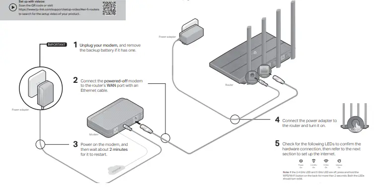
Set up with videos:
Scan the QR code or visit
https://www.tp-link.com/support/setup-video/#wi-fi-routers to search for the setup video of your product.
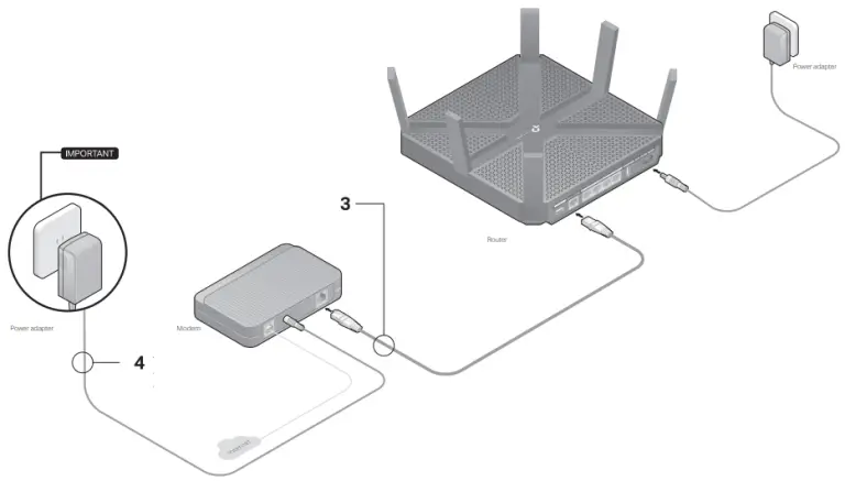
Connect the Hardware
- If your internet connection is through an Ethernet cable from the wall instead of through a DSL / Cable / Satellite modem, connect the Ethernet cable directly to the router’s Internet port, then follow steps 1, 5 and 6 to complete the hardware connection.
- If you already have a router and want to configure this new router as an access point to extend your network, refer to the Access Point Mode section on the back page.

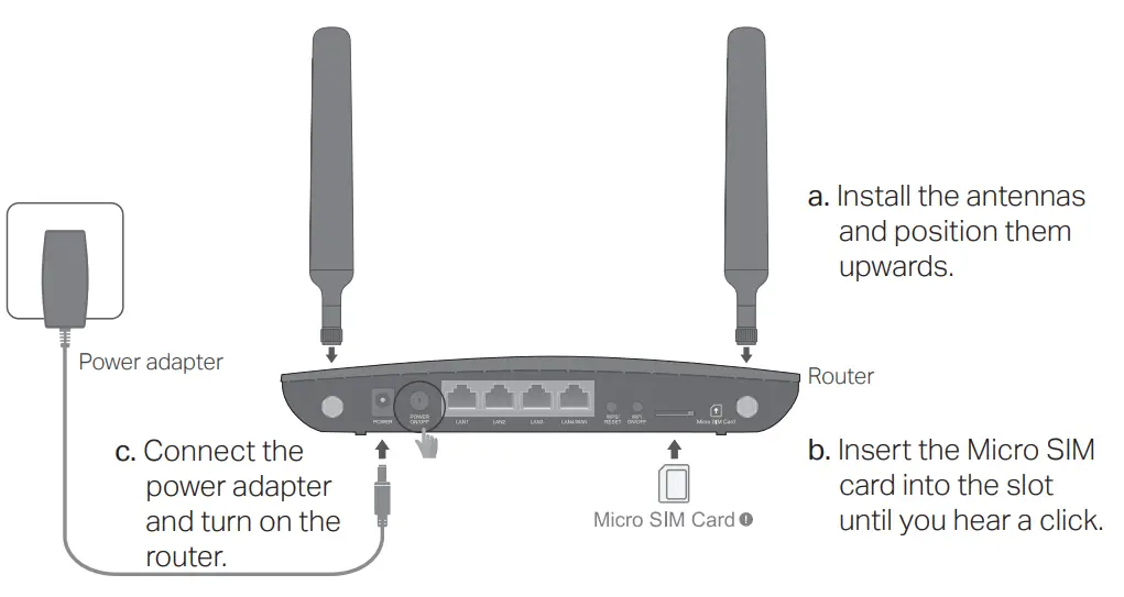
- Place the router horizontally and extend the antennas to the maximum angle.
Note: For best performance, horizontal installation is recommended. Antenna’s direction and position can affect performance in vertical installation situations. - Unplug your modem, and remove the backup battery if it has one.
- Connect the powered-off modem to the router’s Internet port with an Ethernet cable.
- Turn on the modem, and then wait about 2 minutes for it to restart.
- Connect the power adapter to the router and turn it on.

- Check for the following LEDs to confirm the hardware connection, then refer to the next section to set up the internet.
Notes:
- If all the LEDs are off, press the LED On/Off
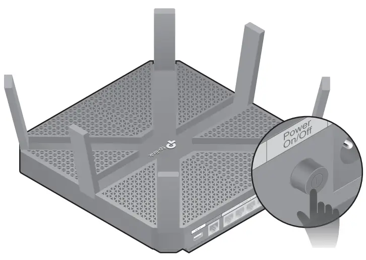 button for about 1 second, then check the LEDs again.
 - If the 2.4GHz, 5GHz-1, and 5GHz-2 LEDs are off, press the Wi-Fi On/Off button
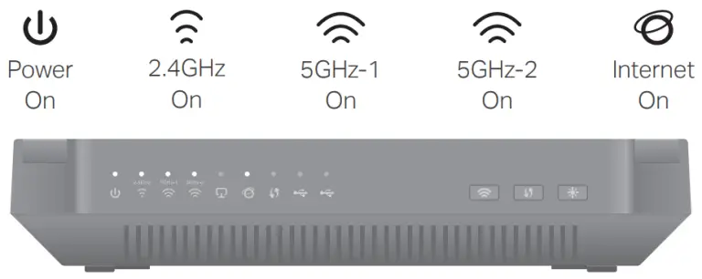 for about 1 second, then the three LEDs should turn solid on
Set Up the Network
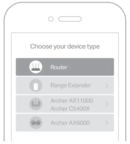
Method 1: Via TP-Link Tether App
- Download the Tether app.


- Open the Tether app and log in with your TP-Link ID.
Note: If you don’t have an account, create one first. - Tap the button in the Tether app and select Router > Wireless Router. Follow the steps to complete the setup and connect to the internet.

Enjoy the internet
Method 2: Via a Web Browser
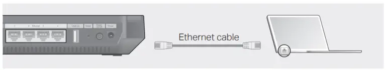
- Connect your device to the router (wired or wireless).
Wired
Turn off the Wi-Fi on your computer and connect to the router using an Ethernet cable.
Wireless- a. Find the SSID and wireless password printed on the label of the router.
- b. Click the network icon of your computer or go to Wi-Fi settings of your smart device, and then select the SSID to join the network.
- Connect the router to the internet.
- a. Launch a web browser, and enter http://tplinkwifi.net or http://192.168.0.1 in the address bar. Create a password to log in.
Note: If the login window does not appear, please refer to Q1 of Need Help? in this guide. - b. Follow the step-by-step instructions to set up the internet connection and register for the TP-Link Cloud service.
- a. Launch a web browser, and enter http://tplinkwifi.net or http://192.168.0.1 in the address bar. Create a password to log in.
Access Point Mode
If you already have a router, you can switch this new router to Access Point mode to extend your existing network. Follow the steps below.
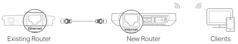
- Power on the router.
- Connect the router’s Internet port to your existing router’s Ethernet port via an Ethernet cable as shown above.
- Connect a computer to the router via an Ethernet cable or wirelessly by using the SSID (network name) and Wireless Password printed on the label at the bottom of the router.
- Launch a web browser, and enter http://tplinkwifi.net in the address bar. Create a password to log in.
- Go to Advanced > Operation Mode, select Access Point and click Save.
- Wait for the router to reboot, then log in and follow the Quick Setup to complete the setup.
Safety Information
- Keep the device away from water, fire, humidity or hot environments.
- Do not attempt to disassemble, repair, or modify the device.
- Do not use damaged charger or USB cable to charge the device.
- Do not use any other chargers than those recommended.
- Do not use the device where wireless devices are not allowed.
- Adapter shall be installed near the equipment and shall be easily accessible.
Change the Router’s Settings
After setup, you can change the router’s settings via the intuitive Tether app, or via a web browser as shown below.
- Connect your device to the router via an Ethernet cable or wirelessly.
- Launch a web browser, enter http://tplinkwifi.net in the address bar, and log in.
Note: If the login window does not appear, please refer to Q1 of Need Help? in this guide. - Change the router’s settings as needed.
| To change: | Go to: |
| Wireless network name and password | Basic > Wireless |
| Login password of the web management page | Basic > TP-Link Cloud
(if you log in via TP-Link ID) |
| Advanced > System Tools > Administration (if you log in via router’s password) |
Need Help?
Q1. What should I do if I cannot access the web management page?
- Reboot your router and try again.
- If the computer is set to a static IP address, change its settings to obtain an IP address automatically.
- Verify that http://tplinkwifi.net is correctly entered in the web browser. Alternatively, enter
http://192.168.0.1 or http://192.168.1.1 in the web browser and press Enter. - Use another web browser and try again.
- Disable then re-enable the network adapter being used.
Q2. What should I do if I cannot access the internet?
- Reboot your modem and router, then try again.
- Check if you have an internet connection by connecting a computer directly to the modem using an Ethernet cable. If you don’t, contact your internet service provider.
- Log in to the web management page of the router, and go to the Basic > Network Map page to check whether the internet IP address is valid or not. If it is not, check the hardware connection or contact your internet service provider.
- For cable modem users, log in to the web management page of the router. Go to Advanced > Network > Internet > MAC Clone, click Use Current Computer MAC Address and click Save, then reboot both the modem and the router.
Q3. How do I restore the router to its factory default settings?
- While the router is powered on, press and hold the Reset button on the back until all LEDs go off, then release the button.
- Log in to the web management page of the router. Go to Advanced > System Tools > Backup & Restore, and click Factory Restore. The router will restore and reboot automatically.
Q4. What should I do if I forget my web management page password?
- If you are using a TP-Link ID to log in, click Forgot password on the login page and then follow the instructions to reset the password.
- Alternatively, press and hold the Reset button on the back until all LEDs go off to reset the router, and then visit http://tplinkwifi.net to create a new login password.
Q5. What should I do if I forget my wireless network password?
- If you haven’t changed the default wireless password, it can be found on the product label at the bottom of the router.
- If you have changed the default wireless password, log in to the router’s web management page, and go to Basic > Wireless to obtain or reset your wireless password.
For technical support, replacement services, user guides, and other information,
please visit https://www.tp-link.com/support, or simply scan the QR code.
To communicate with TP-Link users or engineers, please join the TP-Link Community at https://community.tp-link.com.
If you have any suggestions or needs for our product guides, you are welcome to
email [email protected].
Quick Start Guide
Tapo Security Camera
STEP 1
DOWNLOAD APP
Get the Tapo app from the App Store or Google Play.

https://www.tapo.com/app/download-app/
STEP 2
SET UP
Tap the + button in the app and select your camera model. Follow app instructions to complete setup.
Safety Information
- Do not attempt to disassemble, repair, or modify the device. If you need service, please contact us.
- Do not use a damaged charger or USB cable to charge the device.
- Do not use any other chargers than those recommended.
- Do not use the device where wireless devices are not allowed.
For indoor camera
- Keep the device away from water, fire, humidity or hot environments.
- The adapter shall be installed near the equipment and shall be easily accessible.
For outdoor camera
- Keep the device away from fire or hot environments. DO NOT immerse in water or any other liquid.
- The adapter shall be easily accessible.
Please read and follow the above safety information when operating the device. We cannot guarantee that no accidents
or damage will occur due to improper use of the device. Please use this product with care and operate at your own risk.
TP-Link hereby declares that the device is in compliance with the essential requirements and other relevant provisions of directives 2014/53/EU, 2009/125/EC, 2011/65/EU, and (EU)2015/863.
The original EU Declaration of Conformity may be found at https://www.tapo.com/support/ce/.
TP-Link hereby declares that the device is in compliance with the essential requirements and other relevant provisions of the Radio Equipment Regulations 2017.
The original UK Declaration of Conformity may be found at https://www.tp-link.com/support/ukca/.
For TP-Link Branded Products Only. For more information about the warranty, please visit https://www.tapo.com/support
THIS WARRANTY GIVES YOU SPECIFIC LEGAL RIGHTS, AND YOU MAY HAVE OTHER RIGHTS THAT VARY FROM STATE TO STATE (OR BY COUNTRY OR PROVINCE).
TO THE EXTENT ALLOWED BY LOCAL LAW, THIS WARRANTY AND THE REMEDIES SET FORTH ARE EXCLUSIVE AND IN LIEU OF ALL OTHER WARRANTIES, REMEDIES AND CONDITIONS.
TP-Link warrants the TP-Link branded hardware product contained in the original packaging against defects in materials and workmanship when used normally according to TP-Link’s guidelines for some period which depends on the local service from the date of original retail purchase by the end-user purchaser.
?
Visit www.tapo.com/support for technical support, user guides, and more information
7106509582 REV1.2.0
© 2022 TP-Link
]]>TP-Link TL-WN8200ND 300Mbps Wireless USB Adapter

For Mac OS X
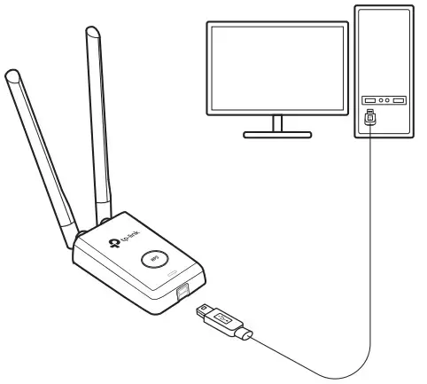
Connect to a Computer
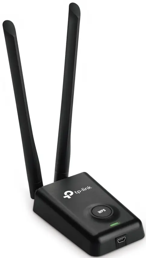
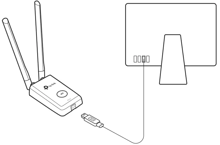
Install the antennas and connect the adapter to your computer using the USB cable provided.
Install Driver and Utility
- a. Download the driver and utility from this product’s Support page at www.tp-link.com.
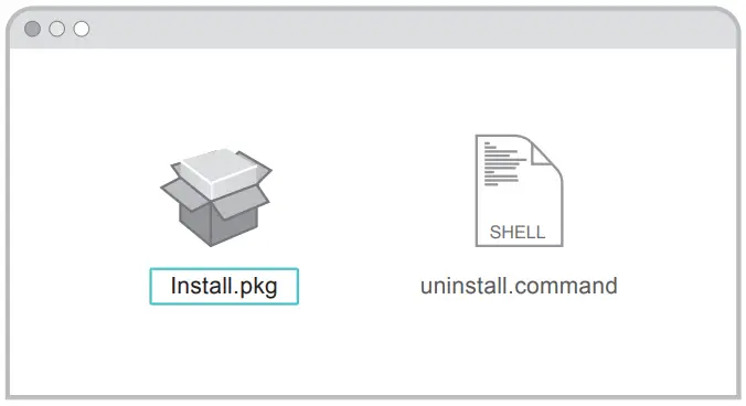
Note: If your computer has a CD drive, you can also run the included CD to install the driver and utility. - b. Unzip the downloaded folder and run the Install.pkg.
- c. Follow the instructions to complete the installation.
Join a Wireless Network
Option 1: Via TP-Link Utility
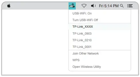
- a. Click
 (TP-Link Utility) on the menu bar.
 - b. Select your Wi-Fi network and enter the Wi-Fi password when prompted.

Option 2: Via Wi-Fi Protected Setup (WPS)
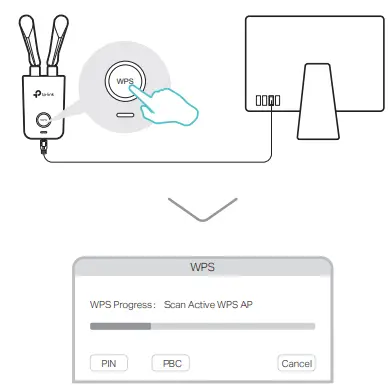
- a. Press the WPS button on your router.
- b. Within 2 minutes, press and hold the WPS button on the adapter until the WPS progress window appears.
- c. When the “WPS Protocol Finished!” message appears, click OK.
For Windows
Connect to a Computer
Install the antennas and connect the adapter to your computer using the USB cable provided.
Install Driver and WPS Tool
- a. Insert the CD and run the Autorun.exe.
Note: You can also download the driver from this product’s Support page at www.tp-link.com. - b. Select TL-WN8200ND and follow the steps to install the driver and WPS Tool.
Note: If you can’t install the driver successfully, disable the antivirus software and firewall, then try again.
Join a Wireless Network
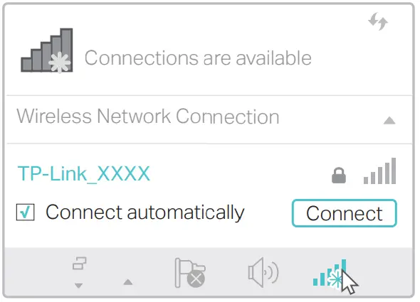
Option 1: Via Windows Wireless Utility
- a. Click the network icon (
 or
or  ) on the taskbar.
 - b. Select your Wi-Fi network, click Connect, and enter the password when prompted.

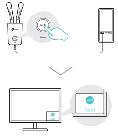
Option 2: Via WPS Tool
- a. Press the WPS button on your router.
- b. Within 2 minutes, press and hold the WPS button on the adapter until WPS Tool opens.
- c. When the “Success!” message appears, your computer is connected to Wi-Fi.
Support
For detailed instructions, please refer to the User Manual from this product’s Support page at www.tp-link.com. For technical support and other information, please visit http://www.tp-link.com/support, or simply scan the QR code.
This USB Adapter can only be powered by computers that comply with Limited Power Source (LPS).
FAQ’s
Yes, the TP-Link TL-WN8200ND can be used in conjunction with a Wi-Fi extender or repeater to further extend the wireless coverage in your home or office.
Yes, the TP-Link TL-WN8200ND supports ad-hoc wireless network connections, allowing you to connect directly to other devices without the need for a router or access point.
The TP-Link TL-WN8200ND has a high-power transmission capability of up to 500mW, providing stronger and more stable wireless signals.
Yes, the TP-Link TL-WN8200ND supports Wi-Fi roaming, allowing seamless connectivity when moving between different access points within the same network.
Yes, the TP-Link TL-WN8200ND offers Linux drivers for compatibility with Linux-based operating systems.
Yes, the TP-Link TL-WN8200ND supports various wireless security protocols, including WEP, WPA, and WPA2, to ensure secure data transmission.
The TP-Link TL-WN8200ND is designed to be directly connected to a USB port on your computer or laptop. While it may work with certain USB hubs, it is recommended to connect it directly for optimal performance.
Yes, the TP-Link TL-WN8200ND comes with a CD containing the necessary drivers and software for installation. You can also download the latest drivers from the TP-Link website.
The TP-Link TL-WN8200ND is primarily designed for regular wireless connectivity and may not support advanced functions such as packet injection or monitoring mode.
Yes, the TP-Link TL-WN8200ND supports WPS, allowing for a convenient and secure wireless setup with compatible routers or access points.
Yes, multiple TP-Link TL-WN8200ND adapters can be used simultaneously on a single computer or across multiple devices for expanded wireless connectivity.
The TL-WN8200ND from TP-Link can support wireless data rates of up to 300Mbps.
No, the TP-Link TL-WN8200ND is powered directly by your computer or laptop’s USB port.
Only Windows operating systems are compatible with the TP-Link TL-WN8200ND.
No, only the 2.4GHz frequency band is used by the TP-Link TL-WN8200ND.
Yes, the TP-Link TL-WN8200ND has a removable high-gain antenna for more flexibility and signal strength.
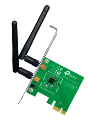
300Mbps Wireless N PCI Express Adapter
TL-WN881ND
About This Guide
This guide is a complement to the Quick Installation Guide. The Quick Installation Guide instructs you on quick installation, and this guide provides the product overview and
detailed instructions for each step.
When using this guide, please notice that the features of the adapter may vary slightly depending on the model and software version you have. All screenshots, images, parameters and descriptions documented in this guide are used for demonstration only.
Conventions
In this guide, the following conventions are used:
| Convention | Description |
| Teal Italic | Hyperlinks are in teal italic. You can click to redirect to a website or a specific section. |
| Teal | Contents to be emphasized and texts on the web page are in teal, including the menus, items, buttons, etc. |
 Note: Note: |
Ignoring this type of note might result in a malfunction or damage to the device. |
 Tips: Tips: |
Indicates important information that helps you make better use of your device. |
More Info
- The latest driver can be found at Download Center at http://www.tp-link.com/support.
- The Quick Installation Guide (QIG) can be found where you find this guide or inside the package of the product.
- Specifications can be found on the product page at http://www.tp-link.com.
- Our Technical Support contact information can be found at the Contact Technical Support page at http://www.tp-link.com/support.
Chapter 1 Get to Know About YourAdapter
This chapter introduces what the adapter can do and shows its appearance.
This chapter contains the following sections:
- Product Overview
- LED Status
Product Overview
The TP-Link Wireless PCI Express Adapter connects your desktop computer to a Wi-Fi network for lag-free video streaming, online gaming, secure internet surfing, and internet calls.
- Compatible with 802.11b/g/n products
- Supports ad-hoc and infrastructure mode
- The maximum speed of up to 300Mbps for a 2.4GHz network
- 2×2 MIMO for more efficient data transfer
- Supports WEP, WPA/WPA2, WPA-PSK/WPA2-PSK
- Supports Windows and Linux
LED Status

You can check the adapter’s working status by following the LED Explanation table.
| Status | Indication |
| Off | The driver has not been installed. The adapter’s radio has been disabled. |
| Flashing Slowly | The driver has been installed but no data is being transmitted or received. |
| Note: | Data is being transmitted or received. |
 Tips:
Tips:
If the LED is off, try these troubleshooting tips:
- Remove and reinstall the adapter.
- Refer to Troubleshooting-T2 to check if the adapter is recognized and enabled. Reinstall the adapter software, if necessary.
Chapter 2 Connect to a Computer
This chapter introduces how to install the adapter into your computer.
Follow the steps below to insert the adapter into your computer:
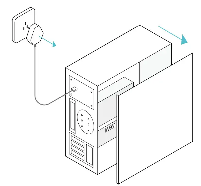
- Turn off the computer, unplug the power cable and remove the case panel.

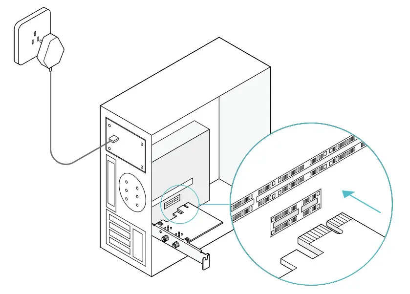
- Locate an available PCI-E slot and carefully insert the adapter.
- Connect the antennas to the adapter.
- Replace the case panel, plug in the power cable and turn on your computer.
Note: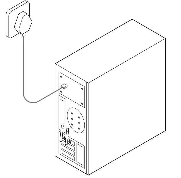
If the bracket is not suitable for your computer, detach it from the adapter’s board and replace it with the low-profile bracket provided.
After connecting your adapter to the computer, please follow the instructions in the appropriate chapter for your operating system: Windows, Linux.
Chapter 3 Windows
This chapter introduces how to install your adapter’s driver, use your adapter to join a wireless network, and uninstall the driver in a Windows system. The adapter is equipped with a setup wizard, which can guide you through the installation process.
This chapter includes the following sections:
- Install Driver
- Join a Wireless Network
- Uninstall Driver
Install Driver
Follow the steps below to set up your adapter:
- Insert the Resource CD into your CD drive and run the Autorun.exe.
Note:
You can also download the driver from the product’s Support page at www.tp-link.com. - Select TL-WN881ND and follow the instructions to continue the installation.
Note:
If you can’t install the driver successfully, disable the antivirus software and firewall, then try again.
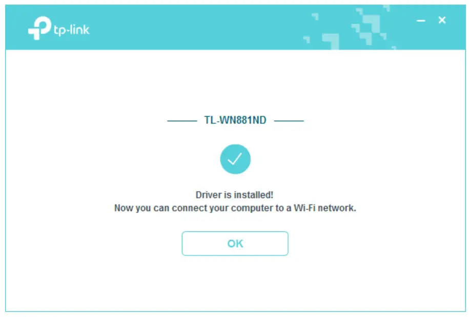
- When the following screen appears, the driver has been installed successfully.

Join a Wireless Network
You can join a wireless network via Windows Wireless Utility.
Follow the instructions below to use your computer system’s built-in wireless utility:
- Click,
 or
or 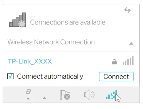 (Network icon) on the taskbar. Select the Wi-Fi network you want to join, and click Connect. Enter the network password when prompted.
 - When the network icon changes to
 , it indicates a successful network connection.
Uninstall Driver
The software uninstallation steps vary a bit in different systems, please follow the appropriate instructions for your Windows operating system: Windows 8/8.1/10, Windows 7.
- Windows 8/8 1/10
Go to Start > Apps, find the TP-Link application. Click Uninstall TP-Link TL-WN881ND
Driver, then follow the on-screen instructions to complete the uninstallation. - Windows 7
Go to Start > All Programs > TP-Link > Uninstall TP-Link TL-WN881ND Driver. Follow the on-screen instructions to complete the uninstallation.
Chapter 4 Linux
Visit the TP-Link’s website at http://www.tp-link.com, and go to TL-WN881ND’s product page. Then find the compatible version of the driver in the support page. Download and install the driver on your computer.
Appendix: Troubleshooting
T1. What should I do if the adapter is not detected?
- Make sure the adapter is securely located in the appropriate PCI-E slot.
- Make sure you meet the minimum system requirements for the adapter and that the latest Windows and system updates are installed on your computer.
- Make sure you use the latest driver for your specific adapter. The latest drivers can be found at the product’s Support page at http://www.tp-link.com.
- Try a different PCI-E slot on the computer.
- Try restarting the computer or try the adapter on a different computer.
T2. How to check if I have installed the driver for my adapter successfully or not?
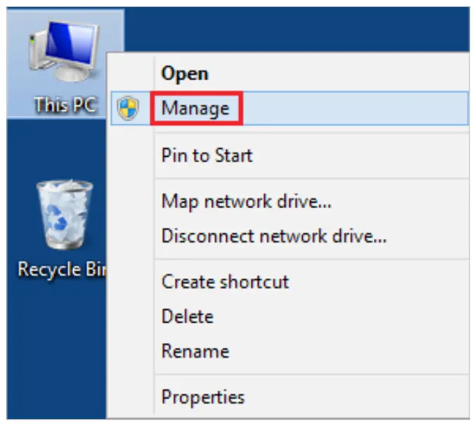
- On your computer, please right-click the Computer icon and go to Manage;
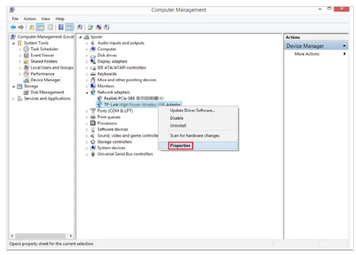
- Open the Device Manager and go to Network adapters, and then find the corresponding TP-Link adapter, right-click it, and then go to Properties;
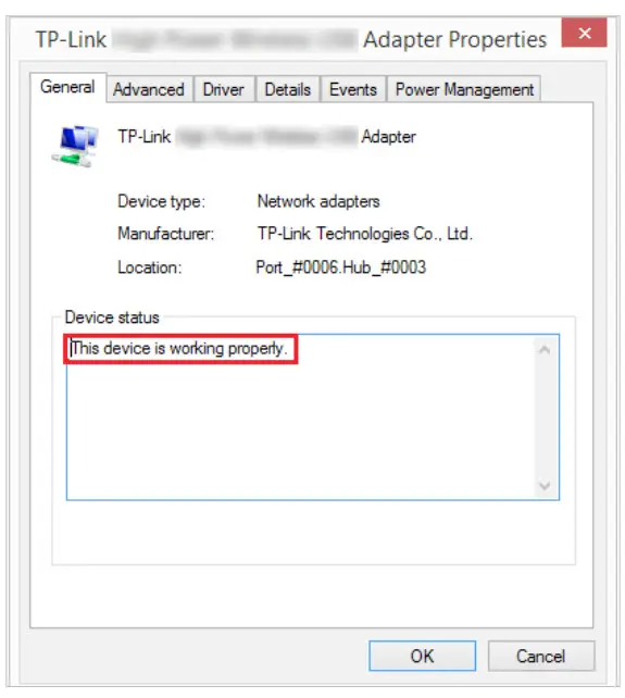
- If you can see “This device is working properly.” in the red box, you have already installed the driver successfully.

T3. What should I do if can’t connect to the Wi-Fi after installing the driver?
- Refer to T2 to check if you have installed the driver for your adapter successfully.
- Disable the antivirus software and firewall, then try again.
- Make sure the adapter is securely located in the appropriate PCI-E slot.
- Try a different PCI-E slot on the computer.
- Restart your computer and try again.
- Re-install the driver and try again.
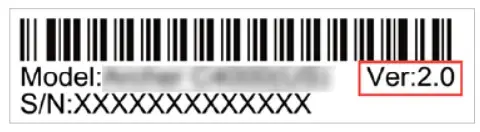
T4. How to find the hardware version of the adapter?
The hardware version is printed on the product label on the package or the adapter.
There is a character string “Ver: X.Y” (for example, Ver:2.0) in the Serial Number field, and the number X is the hardware version of the adapter.

FCC STATEMENT
![]()
This equipment has been tested and found to comply with the limits for a Class B digital device, pursuant to part 15 of the FCC Rules. These limits are designed to provide reasonable protection against harmful interference in a residential installation. This equipment generates, uses, and can radiate radio frequency energy and, if not installed and used in accordance with the instructions, may cause harmful interference to radio communications. However, there is no guarantee that interference will not occur in a particular installation. If this equipment does cause harmful interference to radio or television reception, which can be determined by turning the equipment off and on, the user is encouraged to try to correct the interference by one or more of the following measures:
- Reorient or relocate the receiving antenna.
- Increase the separation between the equipment and receiver.
- Connect the equipment into an outlet on a circuit different from that to which the receiver is connected.
- Consult the dealer or an experienced radio/ TV technician for help.
This device complies with part 15 of the FCC Rules. Operation is subject to the following two conditions:
- This device may not cause harmful interference.
- This device must accept any interference received, including interference that may cause undesired operation.
Any changes or modifications not expressly approved by the party responsible for compliance could void the user’s authority to operate the equipment.
Note: The manufacturer is not responsible for any radio or TV interference caused by unauthorized modifications to this equipment. Such modifications could void the user’s authority to operate the equipment.
FCC RF Radiation Exposure Statement:
This equipment complies with FCC RF radiation exposure limits set forth for an uncontrolled environment. This device and its antenna must not be co-located or operating in conjunction with any other antenna or transmitter. “To comply with FCC RF exposure compliance requirements, this grant is applicable to only Mobile Configurations. The antennas used for this transmitter must be installed to provide a separation distance of at least 20 cm from all persons and must not be co-located or operating in conjunction with any other antenna or transmitter.”
CE Mark Warning

This is a class B product. In a domestic environment, this product may cause radio interference, in which case the user may be required to take adequate measures.
OPERATING FREQUENCY(the maximum transmitted power) 2412MHz—2472MHz(20dBm)
EU declaration of conformity TP-Link hereby declares that the device is in compliance with the essential requirements and other relevant provisions of directives 2014/53/EU, 2009/125/EC and 2011/65/EU.
The original EU declaration of conformity may be found at http://www.tp-link.com/en/ce
RF Exposure Information
This device meets the EU requirements (2014/53/EU Article 3.1a) on the limitation of exposure of the general public to electromagnetic fields by way of health protection.
The device complies with RF specifications when the device is used at 20 cm from your body.
Canadian Compliance Statement
This device complies with Industry Canada license-exempt RSS. Operation is subject to the following two conditions:
- This device may not cause interference, and
- This device must accept any interference, including interference that may cause undesired operation of the device.
Radiation Exposure Statement:
This equipment complies with IC radiation exposure limits set forth for an uncontrolled environment. This equipment should be installed and operated with a minimum distance 20cm between the radiator & your body.
| Ant. | Brand | P/N | Antenna Type | Connector | Gain (dBi) |
| 1 | TP-Link | 3101501266 | Dipole Antenna | Reversed-SMA | 2. |
| 2 | TP-Link | 3101501266 | Dipole Antenna | Reversed-SMA | 2. |
Industry Canada Statement
CAN ICES-3 (B)/NMB-3(B)

Safety Information
- Keep the device away from water, fire, humidity or hot environments.
- Do not attempt to disassemble, repair, or modify the device
- Do not use a damaged charger or USB cable to charge the device.
- Do not use the device where wireless devices are not allowed.
Please read and follow the above safety information when operating the device. We cannot guarantee that no accidents or damage will occur due to improper use of the device. Please use this product with care and operate at your own risk.
Explanation of the symbols on the product label
| Symbol | Explanation |
 |
RECYCLING This product bears the selective sorting symbol for waste electrical and electronic equipment (WEEE). This means that this product must be handled pursuant to European directive 2012/19/EU in order to be recycled or dismantled to minimize its impact on the environment. The user has the choice to give his product to a competent recycling organization or to the retailer when he buys new electrical or electronic equipment. |
Range Extender
Power On
Plug the extender into a power outlet next to your router. Wait until its Power LED turns solid on.
Note: For safety, only plug the extender in the direction is shown below.

Set-Up
Via the Tether App
- Get the up-to-date Tether app from the Apple App Store or Google Play, or simply scan the QR code.

- Launch the Tether app and log in with your TP-Link ID. If you don’t have an account, create one first.

- Tap the button and select Range Extender.
Note: If you cannot find your device, please refer to FAQ > Q1.
- Follow app instructions to complete the setup.
The RE LED should turn solid on, indicating a successful connection to your router.
Note: If the LED does not turn solid on, please refer to FAQ > Q2.
More Setup Methods
Via a Web Browser
- Connect your computer or smartphone to the extender’s network TP-Link_Extender.
- Visit http://www.tplinkrepeater.net or http://192.168.0.254 in a web browser.
Create a password to log in. - Follow web instructions to complete the setup.
Via the WPS Button
- Press the WPS button on your router.
- Within 2 minutes, press the WPS button on the extender for 1 second. The RE LED should change from blinking to solid, indicating a successful connection.
Extended Network Name: Router’s network name with _EXT at the end
Password: Same as your router
For more details, please refer to the user guide at https://www.tp-link.com/support/download/.
Relocate
- Plug in the extender about halfway between your router and the Wi-Fi dead zone. The location you choose must be within the range of your router.
- Wait for about 2 minutes until 3 or more
 LEDs light up. If not, relocate the extender closer to the router to achieve better signal quality.
 https://www.tp-link.com/support/faq/3103/
Tip: To place the extender for optimal Wi-Fi performance, access extender settings via the Tether app and go to Tools > Location Assistant, or simply scan the QR code to visit https://www.tp-link.com/support/faq/3103/.

Enjoy!
Connect your devices to the extender wirelessly or via an Ethernet cable, then enjoy the internet. The password of your extended network is the same as your host router.
Tip: You can also set up the extender in Access Point mode to transform your existing wired network into a wireless one. For details, refer to the user guide at https://www.tp-link.com/support/download/.

Access Extender Settings
After setup, you can access extender settings via any of the methods below. You can reselect the host networks, change extended network settings, and more.
Note: If your extender and router use the same network name, Method 1 is recommended.
Method 1: Via the Tether App

- Connect your smartphone to the extender‘s or router’s network.
- Launch the Tether app, select your extender, and log in.
- View or change extender settings as needed.
Method 2: Via a Web Browser

- Connect your computer or smartphone to the extender’s network. If you are using a computer, unplug the Ethernet cable if any.
- Launch a web browser, enter http://www.tplinkrepeater.net in the address bar, and log in.
- View or change extender settings as needed.
LED Explanation

| LED | Status | Indication (For Range Extender Mode) |
| RE | On/Off Blinking | The extender is connected or not connected to your router’s wireless network. WPS connection is in progress. |
| Wireless | On/Off | The extender’s wireless function is enabled or disabled. |
| Power | On/Off Blinking | The extender is on or off. The system is starting up or a firmware upgrade is in progress. |
| On/Off | Indicates the Wi-Fi connection between the extender and the router. More lit LEDs indicate better signal strength. | |
| Ethernet | On/Off | The Ethernet port is connected or not connected to a powered-on device. |
FAQ (Frequently Asked Questions)
Q1. What should I do if the Tether app cannot find my device during setup?
Try another method by following the steps below:
- Connect your smartphone to the extender’s network TP-Link_Extender.

- Launch the Tether app, and select your extender.
Tip: If you have connected to the extender’s Wi-Fi but still cannot find your device, try turning off your cellular data.
- Follow app instructions to complete the setup.
If you are still having problems, contact our technical support.
Q2. What should I do if the RE LED doesn’t turn solid on after completing the setup via the Tether app or web browser?
- You may have entered an incorrect Wi-Fi password for your host router during the configuration. Check the password and try again.
- Make sure the extender is close to your router, preferably within 16 feet, and away from large electrical appliances.
- If you have enabled wireless MAC filtering, wireless access control, or access control list (ACL) on your router, disable them first, then follow any method on the front page to complete the configuration.
- Try setting it up via the WPS button.
- Reset the extender and go through the configuration again.
If you are still having problems, contact our technical support.
Q3. How do I reset the extender?
- With the extender powered on, use a pin to press the RESET button for 1 second. The extender will reboot.

![]() If you need more setup help, please visit https://www.tp-link.com/support/faq/3074/, or simply scan the QR code.
If you need more setup help, please visit https://www.tp-link.com/support/faq/3074/, or simply scan the QR code.
 https://www.tp-link.com/support/faq/3074/
Safety Information

- Keep the device away from water, fire, humidity, or hot environments.
- Do not attempt to disassemble, repair, or modify the device. If you need service, please contact us.
- Do not use the device where wireless devices are not allowed.
- The socket outlet shall be installed near the equipment and shall be easily accessible.
Please read and follow the above safety information when operating the device. We cannot guarantee that no accidents or damage will occur due to improper use of the device. Please use this product with care and operate at your own risk.
TP-Link hereby declares that the device is in compliance with the essential requirements and other relevant provisions of directives 2014/53/EU, 2009/125/EC, 2011 /65/EU, and (EU) 2015/863. The original EU Declaration of Conformity may be found at https://www.tp-link.com/en/support/ce
TP-Link hereby declares that the device is in compliance with the essential requirements and other relevant provisions of the Radio Equipment Regulations 2017. The original UK Declaration of Conformity may be found at https://www.tp-link.com/support/ukca
![]() To communicate with TP-Link users or engineers, please join the TP-Link Community at https://community.tp-link.com.
To communicate with TP-Link users or engineers, please join the TP-Link Community at https://community.tp-link.com.
![]() If you have any suggestions or needs for our product guides, you are welcome to email [email protected].
If you have any suggestions or needs for our product guides, you are welcome to email [email protected].
![]() For technical support, replacement services, user manuals, and other information, please visit https://www.tp-link.com/support, or simply scan the QR code.
For technical support, replacement services, user manuals, and other information, please visit https://www.tp-link.com/support, or simply scan the QR code.
 http://www.tp-link.com/support
![]() Setup with videos
Setup with videos
Scan the QR code, or visit
https://www.tp-link.com/download/TL-WA850RE.html
* Images may differ from your actual product.
 https://www.tp-link.com/download/TL-WA850RE.html
300Mbps Wi-Fi Range Extender
Model: TL-WA850RE
©2022 TP-Link 7106509569 REV7.2.0
Quick Installation Guide
Wireless 4G LTE Router
Images may differ from actual products.
©2020 TP-Link 7106508980 REV2.0.0
Connect the Hardware
SIM Card Requirements
- Size: Use a micro SIM card, or manually convert a nano-SIM card using the SIM card adapter and sticker.
Note: To prevent damage, do not insert a nano-SIM card directly, and do not insert an empty SIM card adapter or any other object into the slot. - Direction: With the gold contacts facing down, gently slide the SIM card into the slot.
Verify the Hardware Connection
Check the following LEDs’ status. If the Internet LED![]() is on, your router is connected to the internet successfully.
is on, your router is connected to the internet successfully.

Note: If the Internet LED does not turn on, please refer to Q2 of Need Help? in this guide.
For better internet connection, make sure 2 or 3 bars of the Signal Strength LED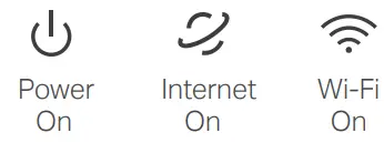 are lit. Otherwise, try relocating the router to a spot that may receive a stronger mobile network signal, such as near a window.
Enjoy the Internet
- Wired
Connect your computers to the router’s LAN ports via Ethernet cables. - Wireless
a. Find the SSIDs (network names) and wireless password printed on the label at the bottom of the router.
b. Click the network icon of your computer or go to the Wi-Fi settings of your smart device, and then select the SSID to join the network.
Customize the 4G LTE Router
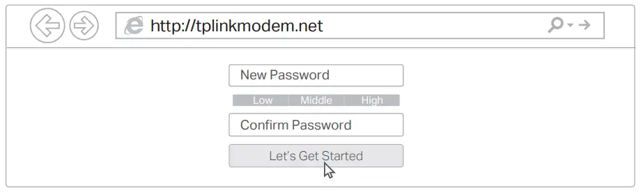
- Make sure your computer is connected to the router (wired or wireless).
- Launch a web browser and type in http://tplinkmodem.net or http://192.168.1.1.
Create a new password for future logins.
Note: If the login page does not appear, please refer to Q1 of Need Help? in this guide. - Follow the step-by-step instructions of the Quick Setup to complete the initial configuration.
Note: The router can also be used (or configured) in Wireless Router Mode for ADSL/Cable connections. For more advanced configurations, please refer to the user guide on TP-Link official website at www.tp-link.com.
Configure the router via Tether App
The TP-Link Tether app provides a simple, intuitive way to access and manage your router.
 |
Block unwelcome users from connecting to your network |
 |
Change the basic wireless network settings |
 |
View information about clients connected to your router |
 |
Set up Parental Controls with access time |
How to begin?
- Download the TP-Link Tether app.

- Open the Tether app and log in with your TP-Link ID.
Note: If you don’t have an account, create one first. - Tap the button in the Tether app and select Router > 3G/4G Router.
Follow the steps to complete the setup and connect to the internet.
Need Help?
Q1. What should I do if I cannot access the web management page?
- If the computer is set to a static IP address, change its settings to obtain an IP address automatically.
- Make sure http://tplinkmodem.net or http://192.168.1.1 is correctly entered in the web browser.
- Use another web browser and try again.
- Reboot your router and try again.
- Disable and enable the active network adapter in use.
Q2. What should I do if I cannot access the internet?
- Verify that your SIM card is an LTE or WCDMA card.
- Verify that your SIM card is in your internet service provider’s service area.
- Verify that your SIM card has sufficient credit.
- Check the LAN connection: Open a web browser and enter http://tplinkmodem.net or http://192.168.1.1 in the address bar. If the login page does not appear, refer to Q1 and then try again.
- Launch a web browser, log in to the web management page, and check the following:
1) Go to Advanced > Network > Internet to verify the parameters provided by your ISP are correctly entered. If the parameters are incorrect, click Create Profile and enter the correct parameters, then select the new profile from the Profile Name list.
2) Go to Advanced > Network > PIN Management to verify if the PIN is required. If it is, enter the correct PIN provided by your ISP, and click Save.
3) Go to Advanced > Network > Data Settings to verify if the Total/Monthly Used exceeds the Total/Monthly Allowance. If it does, click Correct and set Total/Monthly Used to 0 (zero), or disable Data Limit.
4) Go to Advanced > Network > Internet to verify that Mobile Data is enabled. If it is not, enable it to access the internet.
5) Confirm with your ISP if you are in a roaming service area. If you are, go to Advanced > Network > Internet to enable Data Roaming.
Q3. How do I restore the router to its factory default settings?
- With the router powered on, press and hold the RESET button on the rear panel of the router until the Power LED starts flashing, then release the button. Wait while the router resets.
- Log in to the web management page of the router, and go to Advanced > System Tools > Backup & Restore, click Factory Restore and wait until the reset process is complete.
Q4. What should I do if I forget my web management page password?
- Refer to Q3 to reset the router, then create a new password to log in.
Q5. What should I do if I forget my wireless network password?
- The default wireless password is printed on the product label of the router.
- Connect a computer directly to the router using an Ethernet cable. Log in to the router’s web management page and go to Basic > Wireless to retrieve or reset your wireless password.
 For technical support, the user guide, and other information, visit https://www.tp-link.com/support.
Safety Information
- Keep the device away from water, fire, humidity, or hot environments.
- Do not attempt to disassemble, repair, or modify the device.
- Do not use a damaged charger or USB cable to charge the device.
- Do not use any other chargers other than those recommended.
- Do not use the device where wireless devices are not allowed.
- The adapter shall be installed near the equipment and shall be easily accessible.
tp-link Archer-A6 AC1200 Wireless MU-MIMO Wi-Fi Router
Quick Installation Guide

Connect the Hardware
If your internet comes from an Ethernet outlet, connect the router’s WAN port to it, then follow Step 4 and Step 5.
If you want to configure this new router as an access point to extend your network, refer to the Access Point Mode section on the back page.
Set Up the Network
Method 1: Via TP-Link Tether App 1.
- Download the Tether app.
- Open the Tether app and log in with your TP-Link ID.
Note: If you don’t have an account, create one first. - Tap the button in the Tether app and select Router > Wireless Router. Follow the steps to complete the setup and connect to the internet.
Method 2: Via a Web Browser
- Connect your device to the router (wired or wireless).
- Wired
Turn off the Wi-Fi on your computer and connect to the router using an Ethernet cable. - Wireless
- Find the SSID (network name) and Wireless Password printed on the label at the bottom of the router.
- Click the network icon of your computer or go to the Wi-Fi settings of your smart device, and then select the SSID to join the network.
- Wired
- Connect the router to the internet.
- Launch a web browser, and enter http://tplinkwifi.net or http://192.168.0.1
- in the address bar. Create a password to log in.
Note: If the login window does not appear, please refer to Q1 of Need Help? in this guide. - Follow the step-by-step instructions to set up the internet connection and register for the TP-Link Cloud service.
- Launch a web browser, and enter http://tplinkwifi.net or http://192.168.0.1
Access Point Mode
If you already have a router, you can switch this new router to Access Point mode to extend your existing network. Follow the steps below.
- Power on the router.
- Connect the router’s WAN port to your existing router’s Ethernet port via an Ethernet cable as shown above.
- Connect a computer to the router via an Ethernet cable or wirelessly by using the SSID (network name) and Wireless Password printed on the label at the bottom of the router.
- Launch a web browser, and enter http://tplinkwifi.net in the address bar.
- Go to Advanced > Operation Mode and switch to Access Point Mode. Wait for the router to reboot, then log in and follow the Quick Setup to complete the setup.
- Wait for the router to reboot, then log in and follow the Quick Setup to complete the setup
Need Help?
Q1. What should I do if I cannot access the web management page?
- Reboot your router and try again.
- If the computer is set to a static IP address, change its settings to obtain an IP address automatically.
- Verify that http://tplinkwifi.net is correctly entered in the web browser. Alternatively, enter http://192.168.0.1 or http://192.168.1.1 in the web browser and press Enter.
- Use another web browser and try again.
- Disable and enable the network adapter being used.
Q2. What should I do if I cannot access the internet?
- Reboot your modem and router, then try again.
- Check if the internet is working normally by connecting a computer directly to the modem using an Ethernet cable. If it is not, contact your internet service provider.
- Log in to the web management page of the router, and go to the Network Map to check whether the internet IP address is valid or not. If it is not, check the hardware connection or contact your internet service provider.
- For cable modem users, log in to the web management page of the router. Go to Advanced > Network > Internet > MAC Clone, select Clone Current Computer MAC Address and click Save. Then reboot both the modem and the router.
Q3. How do I restore the router to its factory default settings?
- With the router powered on, use a pin to press and hold the RESET button on the back until the Power LED blinks.
- Log in to the web management page of the router, go to Advanced > System Tools
- > Backup & Restore > Factory Default Restore, and click Factory Restore. The router will restore and reboot automatically.
Q4. What should I do if I forget my web management page password?
- If you are using a TP-Link ID to log in, click Forgot password on the login page and then follow the instructions to reset it.
- Alternatively, refer to Q3 to reset your router, then visit http://tplinkwifi.net to create a new login password.
Q5. What should I do if I forget my wireless network password?
- If you have not changed the default wireless password, it can be found on the label at the bottom of the router. Connect a computer directly to the router using an Ethernet cable.
- To communicate with TP-Link users or engineers, please join the TP-Link Community at https://community.tp-link.com. replacement services, user guides, and other information, please visit https://www.tp-link.com/support, or simply scan the QR code.
- If you have any suggestions or needs for our product guides, you are welcome to email [email protected].
Safety Information
- Keep the device away from water, fire, humidity or hot environments.
- Do not attempt to disassemble, repair, or modify the device.
- Do not use a damaged charger or USB cable to charge the device.
- Do not use any other chargers than those recommended.
- Do not use the device where wireless devices are not allowed.
- The adapter shall be installed near the equipment and shall be easily accessible