![]()
Installation Guide
5/8/16-Port Gigabit Easy Smart Switch
LED Explanation
Power
 On: Power on
Off: Power off
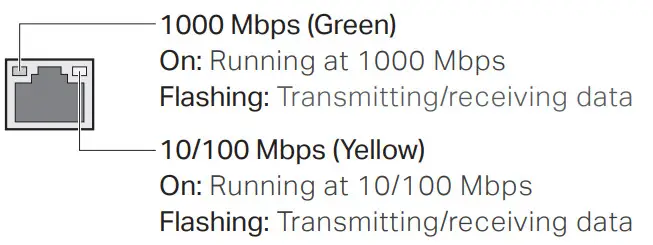
Link/Act
Note: For simplicity, we will take TL-SG108E for example throughout this Guide.
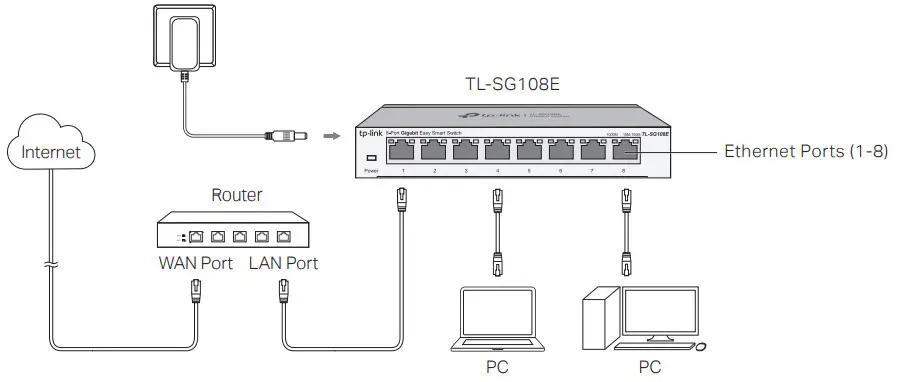
Connection
Configuration
The switch is plug-and-play. To configure the switch, you can use the Web-based GUI or the configuration utility.
The utility is only supported on Windows now.
Using the Web-based GUI
- Find out the IP address of the switch.
• By default, the switch receives an IP address from a DHCP server (or a router that functions as a DHCP server) in your network. You can find out this IP address on the DHCP server.
• If the switch cannot receive an IP address from a DHCP server, it uses the static IP address of 192.168.0.1, with a subnet mask of 255.255.255.0. - Configure IP address on your PC to make sure the switch and PC are in the same subnet.
• If the switch uses an IP address assigned by a DHCP server, set your PC to obtain an IP address automatically from the DHCP server.
• If the switch uses 192.168.0.1 as the IP address, configure your PC’s IP address as 192.168.0.x (”x” ranges from 2 to 254), and subnet mask as 255.255.255.0. - Launch a web browser on your PC, enter the IP address of the switch in the address bar, and press Enter. Log in with admin as both user name and password.
Now you can configure the switch using the Web-based GUI. For further information, refer to the User Guide.
Go to https://www.tp-link.com/support, search the model number of your switch, and you can find this guide on the product Support web page.
Note: If the switch gets a new IP address from the DHCP server, your connection to the switch will be lost. Enter the new IP address in your browser to access the switch again.
Using the Configuration Utility
- Go to https://www.tp-link.com/support and search the model number of your switch. Download the Easy Smart Configuration Utility from the Product Support web page on your PC.
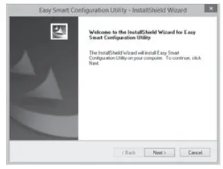
- Decompress the downloaded file, run the installation wizard and follow the prompts to install the Easy Smart Configuration Utility.
- Double click the icon
 on the desktop, and the utility Home page will display a list of TP-Link switches on the local network.
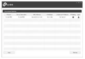
- Click
 to find out the IP parameters of the switch.
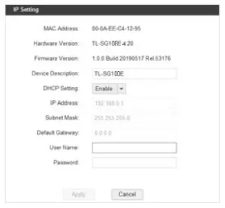 • If the switch uses an IP address assigned by a DHCP server, set your PC to obtain an IP address automatically from the DHCP server.
• If the switch uses 192.168.0.1 as the IP address, configure your PC’s IP address as 192.168.0.x (”x” ranges from 2 to 254), and subnet mask as 255.255.255.0. - Double click the switch that you want to configure. Log in with admin as both user name and password.
Now you can configure the switch using the configuration utility. For further information, refer to the Easy Smart Configuration Utility User Guide. Go to https://www.tp-link.com/support, search the model number of your switch, and you can find this guide on the product Support web page.
Specifications
| General Specifications | |
| Standard | IEEE802.31. IEEE802.3u, IEEE802.3ab. IEEE802.3x, IEEE802.1 p. IEEE802.1 q |
| Protocol | CSMA/CD |
| Data Transfer Rate | Ethernet: 10 Mbps (Half Duplex). 20 Mbps (Full Duplex) Fast Ethernet: 100 Mbps (Half Duplex). 200 Mbps (Full Duplex) Gigabit Ethernet: 2000 Mbps (Full Duplex) |
| Network Media (Cable) | 10Base-T: UTP category 3. 4. 5 cable (maximum 100 m) EINTIA-568 ‘100 0 STP (maximum 100m) 100Base-TX: UTP category 5.5e cable (maximum 100 m) EIA/TIA-568 100 0 STP (maximum 100 rn) 1000Base-T: UTP Category 5e cable (maximum 100 ml EINT1A- 568 100 0 STP (maximum 100 r11) |
| Interface | 5/8/16 10/100/1000 Mbps Auto-Negotiation RJ45 Ports |
| LED indicators | Power. 10/100 Mbps LED, 1000 Mbps LED |
| Transfer Method | Store-and-Forward |
| MAC Address Learning | Automatically learning, automatically aging |
| Frame Forward Rate | 10Base-T: 14881 PPS/Port 100 Base-TX: 148810 PPS/Port 1000 Base-T: 1488095 PPS/Port |
| Wall Mountable | Yes |
| Distance Between Mounting Holes | TL-SG105E: 52 mm TL-SG108E: 110 mm TL-SG 116E: 200 mm |
Environmental and Physical Specifications
| Operating Temperature | 0 ˚C to 40 ˚C (32 ˚F to 104 ˚F) |
| Storage Temperature | -40 ˚C to 70 ˚C (-40 ˚F to 158 ˚F) |
| Operating Humidity | 10% RH to 90% RH non-condensing |
| Storage Humidity | 5% RH to 90% RH non-condensing |
Frequently Asked Questions (FAQ)
Q1. Why is the Power LED not lit?
By default, the Power LED should be lit when the power system is working normally. If the Power LED is not lit, please try the following:
A1: Make sure the power adapter is connected to the switch with power source properly.
A2: Make sure the voltage of the power supply meets the requirements of the input voltage of the switch.
A3: Make sure the power source is ON.
A4: (For TL-SG105E and TL-SG108E) On the LED On/Off configuration page, check whether the LED status is on. By default, the LED status is on.
Q2. Why is the Link/Act LED not lit while a device is connected to the corresponding port?
Please try the following:
A1: Make sure that the cable connectors are firmly plugged into the switch and the device.
A2: Make sure the connected device is turned on and works normally.
A3: The cable must be less than 100 meters long (328 feet).
A4: (For TL-SG105E and TL-SG108E) On the LED On/Off configuration page, check whether the LED status is on. By default, the LED status is on.
Some models featured in this guide may be unavailable in your country or region.
For local sales information, visit https://www.tp-link.com.
 To ask questions, find answers, and communicate with TP-Link users or engineers, please visit https://community.tp-link.com to join TP-Link Community.
 For technical support and other information, please visit https://www.tp-link.com/support, or simply scan the QR code.
 http://www.tp-link.com/support
 If you have any suggestions or needs on the product guides, welcome to email [email protected].
Safety Information
- Keep the device away from water, fire, humidity or hot environments.
- Do not attempt to disassemble, repair, or modify the device. If you need service, please contact us.
- Do not use a damaged charger or USB cable to charge the device.
- Do not use any other chargers other than those recommended.
- The adapter shall be installed near the equipment and shall be easily accessible.
- The plug on the power supply cord is used as the disconnect device, the socket-outlet shall be easily accessible.
- Use only power supplies which are provided by the manufacturer and in the original packing of this product. If you have any questions, please don’t hesitate to contact us.

EU declaration of conformity
TP-Link hereby declares that the device is in compliance with the essential requirements and other relevant provisions of directives 2014/30/EU, 2014/35/EU, 2009/125/EC, 2011/65/EU, and (EU)2015/863.
The original EU declaration of conformity may be found at https://www.tp-link.com/en/ce.
© 2020 TP-Link 7106509035 REV5.0.1