
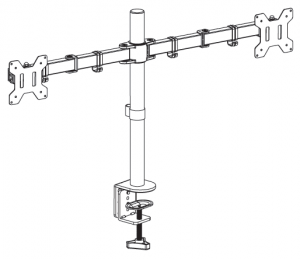
Dual Monitor Desk Mount
SKU: STAND-V002
 Scan the QR code with your mobile device or follow the link for helpful videos and specifications related to this product. https://vivo-us.com/products/stand-v002
GET IN TOUCH | Monday-Friday from 7:00am-7:00pm CST
![]() www.vivo-us.com Chat live with an agent!
www.vivo-us.com Chat live with an agent!
![]() 309-278-5303
309-278-5303

If you do not understand these directions, or if you have any doubts about the safety of the installation, please call a qualified technician. Check carefully to make sure there are no missing or defective parts. Improper installation may cause damage or serious injury. Do not use this product for any purpose that is not explicitly specified in this manual. Do not exceed weight capacity. We cannot be liable for damage or injury caused by improper mounting, incorrect assembly or inappropriate use.
SERIOUS OR FATAL CRUSHING INJURIES CAN OCCUR FROM TIP OVER. TO HELP PREVENT TIP OVER:
- NEVER ALLOW CHILDREN TO CLIMB, STAND, HANG, OR PLAY ON ANY PART OF MONITOR OR STAND.
- USE TIP OVER RESTRAINT OR ANCHOR STAND TO WALL
USE OF TIP OVER RESTRAINTS MAY ONLY REDUCE, BUT NOT ELIMINATE RISK OF TIP OVER.
SMALL PARTS – NOT FOR CHILDREN UNDER 3 YEARS. ADULT SUPERVISION IS REQUIRED.
PACKAGE CONTENTS
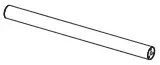
A (x1) Pole
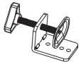
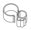
B (x1) Clamp

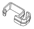
C (x1) Clamp Brace
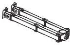
D (x1) Swivel Arm
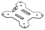
E (x2) VESA Plate

F (x3) M5x14 Bolt

G (x2) M8x12 Bolt

H (x2) Nut

I (x1) M10 Washer

J (x1) Spring Washer

K (x1) Grommet Base Plate
L1 (x1) Wire Clip
L2 (x4) Wire Clip
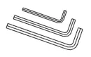
M (x1) Allen Key Set

N (x8) M4x12 Thumbscrew
O (x8) M4x30 Bolt
![]()
P (x8) M4 Spacer
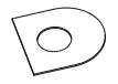
Q1 (x1) Soft Pad

Q2 (x1) Soft Pad
NOTE: SOME HARDWARE INCLUDED MAY NOT BE USED
TOOLS NEEDED

Phillips Screwdriver
DO NOT EXCEED WEIGHT CAPACITY.
Failure to do so may result in serious injury.
![]()
22 lbs Per Arm (10kg)
ASSEMBLY STEPS
STEP 1
Option A: Desk Clamp Install
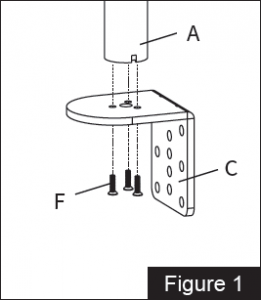
- Install the clamp brace (C) to the pole (A) using x3 M5x14 bolts (F). See Figure 1.
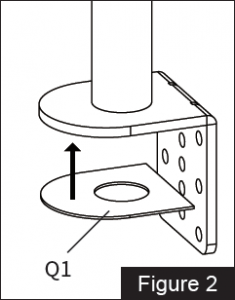
- Attach soft pad (Q1) to the clamp brace (C) , see Figure 2.
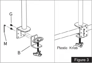
- Install the clamp (B) to the pole assembly according to the thickness of the desktop. The thickness can be changed to 3 positions. Connect using x2 M8x12 bolts (G) and tighten using the Allen wrench (M). Tighten the clamp to the desktop using the plastic knob. See Figure 3.
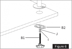
Option B: Grommet Install
- If desk does not have an existing grommet hole, drill a 3/8″ (10mm) diameter hole at the B2 desired position through the mounting surface.
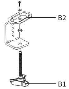
- Completely disassemble clamp (B) into individual parts. Set knob (B1) and clamp plate (B2) aside for later use. The L bracket, bolt, washer and bushing will not be used.
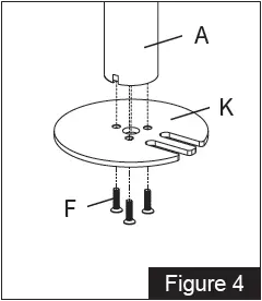
- Install grommet base plate (K) to the pole (A) using x3 M5x14 bolts (F). See Figure 4. B1
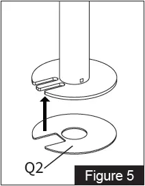
- Attach soft pad (Q2) to the grommet base plate (K), see Figure 5.
- Position pole (A) on the mounting surface and secure using the clamp plate (B2), spring washer (J), M10 washer (I) and knob (B1). See
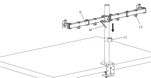
STEP 2
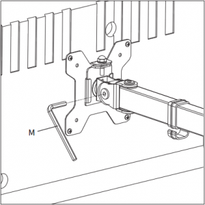
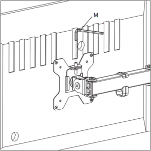
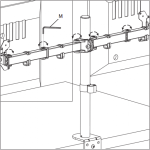
Install swivel arm (D) to the pole (A). Fasten the bolt with supplied Allen wrench (M). Attach the wire clip (L1,L2) to the pole (A) and swivel arm (D).
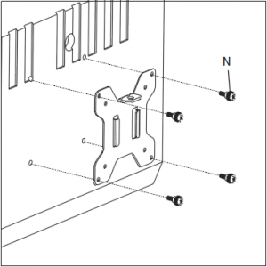
STEP 3
OPTION A: Flat Back Monitor Attach the VESA plate (E) to the monitor with M4x12 thumbscrews (N).
NOTE: Hand tighten screws to avoid over tightening.
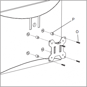
OPTION B: Curved Back Monitor Attach the VESA plate (E) to the monitor with M4x30 bolts (O) and M4 spacers (P).
NOTE: Gently tighten using a screwdriver
STEP 4
Slide the monitor onto the head of swivel arm (D).

Install the security nut (H). Make sure the security nut is installed before you rotate the monitor. For minor height adjustment, use Allen wrench (M).

STEP 5
Tighten the bolt with the supplied Allen wrench (M) to fix the tilt angle.
M To level the monitors, remove the nut (H) and turn the bolt with the Allen wrench (M) to raise or lower the monitor. Replace nut (H) after the adjustment.
STEP 6
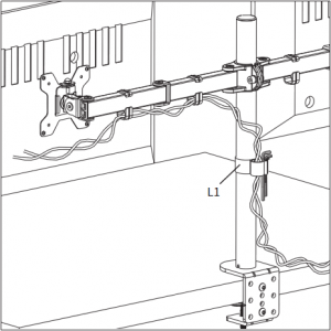
Use the supplied Allen wrench set (M) to make any necessary adjustments. Manage cables and store Allen wrenches (M) in wire clip (L1) for future use.
Love your new VIVO setup and want to share? Tag us in your photo! @vivo_us
LAST UPDATED: 03/09/2021 REV1.1
Open Monday – Friday 7:00am – 7:00pm CST, our dedicated support team can offer immediate assistance with rapid response times. If any parts are received damaged or defective, please contact us. We are happy to replace parts to ensure you have a fully functioning product.
![]() [email protected]
[email protected]
![]() www.vivo-us.com
www.vivo-us.com
Chat live with an agent!
![]() 309-278-5303
309-278-5303
AVG. RESPONSE TIME (within office hrs): 1HR 8M – 23% within < 15m – 38% within < 30m – 61% within < 1hr – 83% within < 2hr – 92% within < 3hr
AVG. RESOLUTION TIME (within office hrs): < 15 M
AVG. RESOLUTION TIME (within office hrs): 5M 4S
FOR MORE VIVO PRODUCTS, CHECK OUT OUR WEBSITE AT: www.vivo-us.com
]]>vivo V2027 Smart Phone

Welcome to Vivo
This Quick Start Guide tells you how to set up your phone and use its key features. For more detailed instructions, turn on your phone, then go to Settings > About phone > Customer service > Manual. You can also learn more useful information on vivo’s official website. For legal information, go to Settings > About phone > Legal information. For the FCC ID of this phone, please go to Settings > About phone> FCC ID. The features and images shown in this guide are for reference only. They may differ from the actual product.
Appearance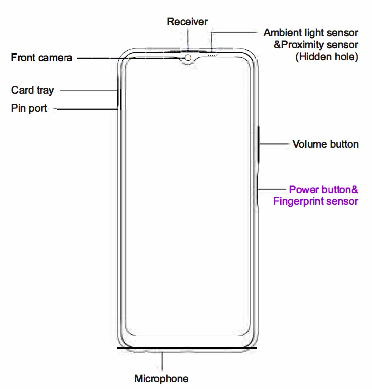
Special Instructions
Ambient Light Sensor & Proximity Sensor
The ambient light sensor and proximity sensor of this device are hidden on the right side of the receiver. To ensure the sensors function well, please keep them away from any dust, grease or light-proof film. Using a third-party screen protector may cause the sensors to block alerts or lock the screen nonresponsive to incoming calls, so you need to cut the film to expose the sensors.
Product Technical Specifications
| Product name | Mobile phone |
| Product model | V2027 |
|
Camera |
Front: 8MP
Rear: 13MP + 2MP + 2MP |
| Battery | 5000mAh (TYP) |
| Dimensions | 164.41 x 76.32 x 8.41mm |
| Screen | 16.55cm (6.51) 1600 x 720 |
| Optimum operating temperature is o•c to 35’C and optimum storage temperature is -20’C to 45’C. Extreme heat or cold may damage your device or accessories. | |
Optimum operating temperature is o•c to 35’C and the optimum storage temperature is -20’C to 45’C. Extreme heat or cold may damage your device or accessories.
5G WiFi statement
Operation in the band 5150-5350MHz is only for indoor use to reduce the potential for harmful interference to co-channel mobile satellite systems.
Product Standard Accessories
- Cell phone x 1 Pin x 1
- Charger x 1 Warranty card x 1
- USB cablex 1 Quick start guide x 1
- Phone case x 1 Headset x 1
FCC SAR
- Head : 0.98 W/kg
- Body-worn: 0.66 W/kg ( 15mm distance)
- Hotspot: 1.07 W/kg ( 10mm distance)
FCC statement
This device complies with part 15 of the FCC Rules. Operation is subject to the following two conditions:
- This device may not cause harmful interference, and
- This device must accept any interference received, including interference that may cause undesired operation.
The wireless telephone industry has developed ratings to assist hearing device users in finding wireless devices that may be compatible with their hearing devices. Not all wireless devices have been rated. Wireless devices that are rated will have the rating displayed on the box together with other relevant approval markings. The ratings are not guarantees. Results will vary depending on the user’s hearing device and hearing loss. If your hearing device is vulnerable to interference, you may not be able to use a rated wireless device successfully. Consulting with your hearing health professional and testing the wireless device with your hearing device is the best way to evaluate it for your personal needs. This smartphone has been tested and rated for use with hearing aids for some of the wireless technologies that the smartphone uses. However, other wireless technologies may be used in this smartphone that have not been tested for use with hearing aids. It is important to try the different features of your smartphone thoroughly and in different locations to determine if you hear any interfering noise when using this smartphone with your hearing aid or cochlear implant. Consult your wireless service provider about its return and exchange policies, and for information about hearing aid compatibility. Hearing aid compatibility rating for this smartphone: M3 M-Ratings: Wireless devices rated M3 or M4 meet FCC requirements and are likely to generate less interference to hearing devices than wireless devices that are not labeled. M4 is the better or higher of the two ratings. Hearing devices may also be measured for immunity to this type of interference. Your hearing device manufacturer or hearing health professional may help you find results for your hearing device. The more immune your hearing aid is, the less likely you are to experience interference noise from wireless devices.
Caution: Changes or modifications not expressly approved by the vivo Mobile Communication Co.,Ltd. could void the user’s authority to operate the equipment.
Note: This equipment has been tested and found to comply with the limits for a Class B digital device, pursuant to part 15 of the FCC Rules. These limits are designed to provide reasonable protection against harmful interference in a residential installation. This equipment generates, uses, and can radiate radio frequency energy and, if not installed and used in accordance with the instructions, may cause harmful interference to radio communications. However, there is no guarantee that interference will not occur in a particular installation. If this equipment does cause harmful interference to radio or television reception, which can be determined by turning the equipment off and on, the user is encouraged to try to correct the interference by one or more of the following measures:
- Reorient or relocate the receiving antenna.
- Increase the separation between the equipment and receiver.
- Connect the equipment to an outlet on a circuit different from that to which the receiver is connected.
- Consult the dealer or an experienced radio/TV technician for help.
SAR statement
This device meets the government’s requirements for exposure to radio waves. This device is designed and manufactured not to exceed the emission limits for exposure to radio frequency (RF) energy set by the Federal Communications Commission of the U.S. Government. The SAR limit set by the FCC is 1.6W/Kg. For body-worn operation, this device has been tested and meets the FCC RF exposure guidelines for use with an accessory that contains no metal and positions the device a minimum of 15mm from the body. RF exposure compliance with any body-worn accessory that contains metal was not tested and certified, and the use of such body-worn accessories should be avoided. Accessory available in the market and must be used to keep use distance 15mm from EUT to body-worn operation.
HAC statement
When wireless devices are used near hearing devices (such as hearing aids and cochlear implants), users may detect a buzzing, humming, or whining noise. Some hearing devices are more immune than others to this interference, and wireless devices also vary in the amount of interference that they generate.
Pink Electric Commercial Cotton Candy Machine
View Fullscreen
Pink Electric Commercial Cotton Candy Machine
Instruction Manual
SKU: CANDY-V002
Scan the QR code with your mobile device or follow the link for helpful videos and specifications related to this product. https://vivo-us.com/products/candy-v002
GET IN TOUCH | Monday-Friday from 7:00am-7:00pm CST
www.vivo-us.com Chat live with an agent!
309-278-5303
WARNING: IMPORTANT SAFETY INFORMATION
READ AND FOLLOW ALL SAFETY REQUIREMENTS KEEP THIS MANUAL IN A SAFE AND DRY PLACE FOR FUTURE REFERENCE
If you do not understand these directions, or if you have any doubts about the safety of the installation, please call a qualified technician. Check carefully to make sure there are no missing or defective parts. Improper installation may cause damage or serious injury. Do not use this product for any purpose that is not explicitly specified in this manual and do not exceed weight capacity. We cannot be liable for damage or injury caused by improper mounting, incorrect assembly or inappropriate use.
· ENSURE THAT SERVICING IS DONE BY PROFESSIONAL SERVICE PERSONNEL, IF APPLICABLE, TO MINIMIZE PRODUCT DAMAGE OR SAFETY ISSUES.
· ALL MINORS MUST BE SUPERVISED WHILE MACHINE IS IN OPERATION. · THIS APPLIANCE IS NOT INTENDED FOR USE BY PERSONS (INCLUDING CHILDREN) WHOSE
PHYSICAL, SENSORY OR MENTAL CAPABILITIES MAY BE DIFFERENT OR REDUCED, OR WHO LACK EXPERIENCE OR KNOWLEDGE, UNLESS SUCH PERSONS RECEIVE SUPERVISION OR TRAINING TO OPERATE THE APPLIANCE BY A PERSON RESPONSIBLE FOR THEIR SAFETY. · PLUG THE MACHINE INTO AN ELECTRICAL OUTLET WITH A GROUND LINE.
WARNING: DO NOT USE IF THE CABLE, ELECTRICAL OUTLET OR PLUG IS BROKEN.
WARNING: TO AVOID ELECTRIC SHOCK, DO NOT TOUCH THE PLUG OR ELECTRIC CABLE IF THEY ARE WET. KEEP THE CABLE AWAY FROM HEAT. DON’T IMMERSE THE CABLE, ELECTRICAL PLUG OR THE MACHINE INTO WATER OR OTHER LIQUIDS.
WARNING: DO NOT USE DETERGENT WHEN CLEANING. ANY REMAINING DETERGENT RESIDUE WILL POLLUTE THE CANDY FLOSS. DO NOT LET MACHINE SOAK IN WATER, AS THIS WILL DAMAGE THE ELECTRICAL COMPONENTS.
CAUTION: FOLLOW INSTRUCTIONS TO PREVENT BURNS. · DO NOT TOUCH THE SURFACE OF THE HEATING HEAD WHILE THE MACHINE IS ON. · DO NOT PLACE HAND INTO THE PAN TO REMOVE THE SUGAR WHILE THE MACHINE IS ON. · DO NOT MOVE THE MACHINE WHILE IT IS ON. · ALLOW THE MACHINE TO COOL BEFORE MOVING IT OR REMOVING EXCESS SUGAR.
ELECTRICAL DATA
2
PRODUCT SPECIFICATIONS
MODEL DIMENSION HEATING POWER MOTOR POWER ELECTRIC VOLTAGE
CANDY-V002 930 x 520 x 860mm
1000 W 80 W 110 V
FREQUENCY
60 Hz
YIELD
1 PER 30 SEC
FUSE
15A 250V (F15)
PACKAGE CONTENTS
A1 (x2) Wheel
A2 (x1) Wheel Leg
A3 (x2) Leg
A4 (x3) Beam
A5 (x6) M5x30 Screw
A6 (x2) M12x70 Screw
A7 (x2) Washer
A8 (x1) Socket Wrench
A9 (x2) Wheel Cover
B1 (x2) Handle Block
B2 (x1) Handle Pipe
B3 (x8) M4x12 Screw
B4 (x8) M5x8 Screw
B5 (x1) Cone Shelf
B6 (x1) Shelf
B7 (x1) Candy Machine
B8 (x4) M5 Nuts
B9 (x4) M5x10 Screw
B10 (x1) Pan
PREPARATION
· After carefully removing the machine from the packing carton, clean the heating head and the
stainless steel pan with warm, soapy water (do NOT use detergent type cleaners). When the head is turned on, it will clear the water from the machine. Make sure to dry the pan completely.
· The cotton candy machine should be placed on a dry, flat stable surface. · Make sure all parts are properly installed before plugging in the machine.
NOTE: Due to the operation testings of the machine prior to shipping, some sugar residue may be remaining.
3
MACHINE STRUCTURE
ASSEMBLY STEPS
STEP 1
Remove all x6 M5x30 screws (A5) from the Beams (A4). Assemble one beam to each side of wheel leg (A2) using x2 M5x30 screws (A5). Connect Legs (A3) to assembly using x2 M5x30 screws (A5) through the upper holes. Finish the assembly as shown by mounting remaining beam (A4) to lower holes in legs (A3) using x2 M5x30 screws (A5).
STEP 2
Mount both wheels (A1) using the wheel screws (A6) and washers (A7). Tighten using small end of included socket wrench (A8).
STEP 3
Press both wheel covers (A9) onto wheels.
4
STEP 4
Flip finished cart over and place (B7) machine on top with drawer facing to the side. Secure with all (B4) M5x8 cart screws.
STEP 5
Press both (B1) handle blocks onto (B2) handle pipe. Secure to (B6) shelf using four (B9) M5x10 screws and four (B8) M5 nuts. Handle should be facing up.
STEP 6
Attach (B5, B6) shelves to machine using all (B3) M4x12 screws. NOTE: Be sure that the shelf with the handle is on the same side as the wheels.
STEP 7
Latch pan (B10) to the top of the machine. Your cotton candy machine is now ready for use!
5
OPERATING INSTRUCTIONS
STEP 1 Turn on the power switch. Let the machine run for 1-2 minutes to allow the motor and drive
belt to warm up for best performance. The machine may vibrate while running; this is normal and will not affect operation.
NOTE: Machine has a built in safety switch (located on front left latch) and will not turn on if the bowl is not fully mounted. All four latches should activate the safety switch. Ensure bowl is in place and secure – red light should be illuminating from the switches.
STEP 2 Turn on the heating switch and allow the head to warm up for 4-5 minutes.
NOTE: To protect candy from debris and prevent the sugar crystals from flying into the air, we suggest purchasing our bubble shield (CANDY-V003) which is sold separately.
STEP 3 OPTION A: CANDY FLOSS SUGAR
If using standard candy floss sugar, pour one scoop full of sugar into the center of the heating head.
OPTION B: HARD CANDY If using hard candy, turn off machine and place hard candy pieces evenly in the center of the heating head. Break up into smaller pieces to fit if necessary. Turn machine back on.
NOTE: Only use corn syrup based hard candies with a slightly transparent appearance such as Jolly Rancher and Life Savers. Pressed sugar and other hard candies like Smarties may not melt properly, thus clogging the head.
WARNING: KEEP HANDS CLEAR OF MOVING PARTS TO REDUCE RISK OF INJURY
STEP 4
The candy floss will form after roughly 30 seconds. Use a paper cone, candy stick, or other related object to collect the candy floss. Revolve the object in a circular motion following the pan. Turn the object sideways directly over the heating head and continue twisting the object in order to collect the floss into a ball shape.
STEP 5 To continue making candy floss, repeat steps 3 and 4. To prolong the service life of the electric
motor, please allow the motor to rest for 20 minutes after working continuously for an hour.
Turn off the power switch when you are finished. Remove the pan and clean it with water.
NOTE: If the heating head does not produce candy floss, turn off the power switch and clean the burnt sugar as described in the Cleaning section.
CARE & MAINTENANCE
CLEANING
When finished making candy floss, keep machine hot and running while cleaning the heating head by slowly pouring a small amount of water into the center.
USE WITH CAUTION: Water will immediately become steam.
6
Keep water spinning through until color inside is closer to the bare aluminum again. Allow machine to cool, and wipe down head with a damp cloth to clean off excess sugar. Stainless steel pan may be cleaned with warm soapy water.
If the inside of the head needs to be cleaned, remove the four screws on top, then remove top plate. If screws are difficult to remove, turn on the machine and heater for 15-20 seconds to free up the screws.
Allow machine to heat back up for one minute before making more candy floss. This will help the machine run well and require only minimal cleaning after each use.
REMOVING BURNT SUGAR
Due to the nature of sugar, it is normal for a small amount to burn inside even with periodic cleanings. This will not harm the machine or candy floss produced.
Remove burnt sugar by removing top plate from heating head and allowing machine to soak in vinegar and then scrubbing clean. An abrasive cleaning pad (such as a Scotch-Brite pad) may be used for especially hard burns.
CHANGING THE BELT
This package includes a spare belt in case the belt currently installed in the machine fails.
To access belt: Remove shields from underneath heating head. Each shield is held in place by three screws. Remove the top cover, which is held in place by a screw on each side.
TROUBLESHOOTING
WARRANTY
We offer a ONE YEAR warranty for this product. If you have any problems with the machine, please contact us directly. We have a 30 Day Return Policy.
PROBLEM
POSSIBLE CAUSE & SOLUTION
Heating head spins but does Ensure wires underneath heating head are not cut or frayed. If wires
not heat up.
are not damaged then the temperature sensor may be out.
Machine has no power.
Bowl may not be secured to machine (all four latches should activate the safety switch). If safety switch is pressed and switches
are on, check if red light is illuminating from switches.
Contact us for further assistance if it is still not working.
Electric cord for machine is lost.
Standard cord used for computers, printers, etc. must be rated 20 AMPS. Cotton candy machine is designed to run on US 110V power.
Head/spinner is off balance. Contact us so that we may send you a
Machine constantly vibrates.
part replacement.
Heating head not turning, motor running.
Ensure belt inside machine has not come loose. If belt has come loose, reinstall in machine and adjust the belt tension by loosening the 4 motor screws and repositioning the motor slightly. Replace
belt if broken.
7
Love your new VIVO setup and want to share? Tag us in your photo! @vivo_us
LAST UPDATED: 02/11/2021 REV1.1
Open Monday – Friday 7:00am – 7:00pm CST, our dedicated support team can offer immediate assistance with rapid response times. If any parts are received damaged or defective, please contact us. We are happy to replace parts to ensure you have a fully functioning product.
[email protected]
www.vivo-us.com
Chat live with an agent!
AVG. RESPONSE TIME (within office hrs): 1HR 8M – 23% within < 15m – 38% within < 30m – 61% within < 1hr – 83% within < 2hr – 92% within < 3hr
AVG. RESOLUTION TIME (within office hrs): < 15 M
309-278-5303
AVG. RESOLUTION TIME (within office hrs): 5M 4S
FOR MORE VIVO PRODUCTS, CHECK OUT OUR WEBSITE AT: www.vivo-us.com
]]> SKU: STAND-V002F
 Scan the QR code with your mobile device or follow the link for helpful videos and specifications related to this product.
https://vivo-us.com/products/stand-v002f
GET IN TOUCH | Monday-Friday from 7:00am-7:00pm CST
[email protected]
www.vivo-us.com Chat live with an agent!
309-278-5303
 WARNING!
If you do not understand these directions, or if you have any doubts about the safety of the installation, please call a qualified technician. Check carefully to make sure there are no missing or defective parts. Improper installation may cause damage or serious injury. Do not use this product for any purpose that is not explicitly specified in this manual. Do not exceed weight capacity. We cannot be liable for damage or injury caused by improper mounting, incorrect assembly or inappropriate use.
TIPOVER WARNING
SERIOUS OR FATAL CRUSHING INJURIES CAN OCCUR FROM TIPOVER. TO HELP PREVENT TIPOVER:
- TO PREVENT TIPPING, PLEASE BE CAREFUL NOT TO EXTEND THE ARMS TOO FAR FORWARD
OR BACKWARD. - NEVER ALLOW CHILDREN TO CLIMB, STAND, HANG, OR PLAY ON ANY PART OF MONITOR OR
STAND. - USE TIPOVER RESTRAINT OR ANCHOR STAND TO WALL
USE OF TIPOVER RESTRAINTS MAY ONLY REDUCE, BUT NOT ELIMINATE RISK OF TIPOVER.
WARNING: CHOKING HAZARD
SMALL PARTS – NOT FOR CHILDREN UNDER 3 YEARS. ADULT SUPERVISION IS REQUIRED.
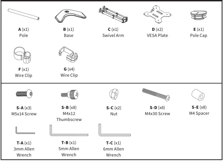
PACKAGE CONTENTS

NOTE: SOME HARDWARE INCLUDED MAY NOT BE USED
TOOLS NEEDED
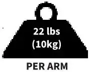
DO NOT EXCEED WEIGHT CAPACITY.
Failure to do so may result in serious injury.
ASSEMBLY STEPS
STEP 1
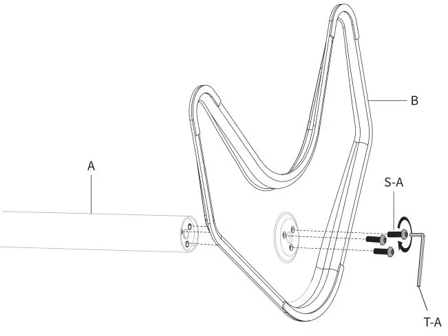
Install the pole (A) to the base (B) using M5x14 Screw (S-A). Tighten with the 3mm Allen wrench (T-A).
 STEP 2
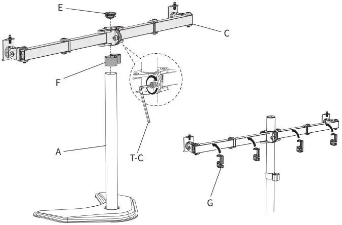
Slide Wire Clip (F) and Swivel Arm (C) down onto the Pole (A) and tighten the screw with 6mm Allen Wrench (T-C). Attach the Pole Cap (E) to the top of the Pole (A). Attach the Wire Clips (G) to the Arms.
 STEP 3
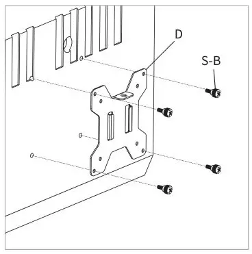
OPTION A: Flat Back Monitor
Attach the VESA plates (D) to the monitors using M4x12 Thumbscrew (S-B).
NOTE: Hand tighten screws to avoid stripping the plastic screw heads.
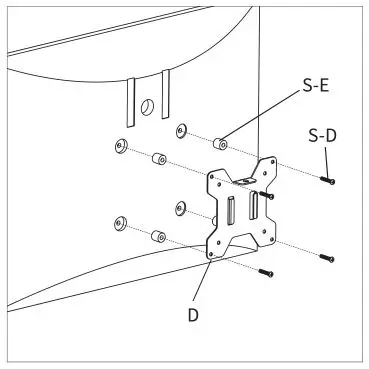
OPTION B: Curved Back Monitor Attach the VESA plates (D) to the monitors using M4 Spacers (S-E) and M4x30 Screws (S-D). Tighten with a Phillips screwdriver.
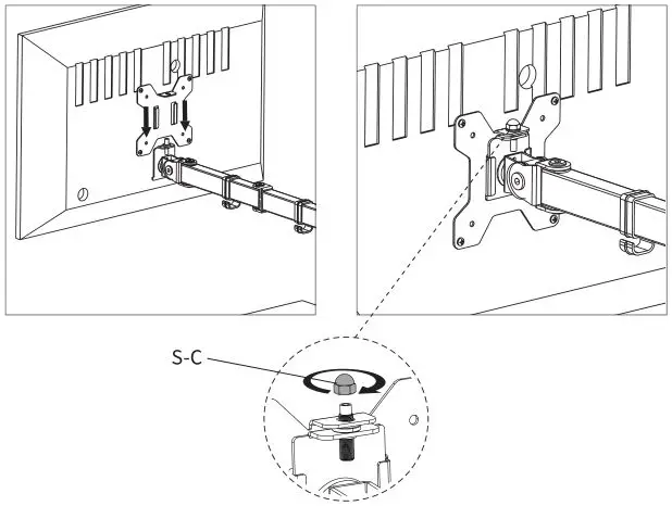
STEP 4
Slide the monitors onto the heads of swivel arm and install the Security Nuts (S-C). Make sure the security nuts are installed before you rotate the monitors.
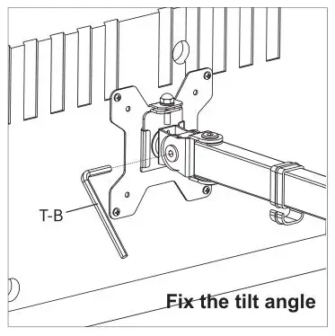
STEP 5
Tighten the bolt on the side of the tilt joint with the 5mm Allen Wrench (T-B) to fix the tilt angle.
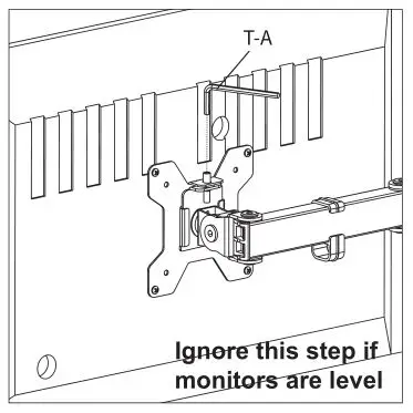
To level the monitors, remove the security nut and turn the bolt with the 3mm Allen Wrench (T-A) to raise or lower the monitor. Replace nut after the adjustment.
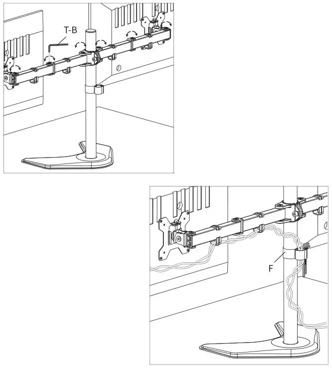
STEP 6
Use the 5mm Allen Wrench (T-B) to adjust swivel joints if needed. Manage cables and store the Allen Wrenches (T-A, T-B, T-C) in Wire Clip (F) for future use.
STEP 7
CAUTION: To prevent tipping, please be careful not to extend the arms too far forward or backward.

Love your new VIVO setup and want to share? Tag us in your photo! @vivo_us
LAST UPDATED: 02/24/2021 REV1.0
Open Monday – Friday 7:00am – 7:00pm CST, our dedicated support team can offer immediate assistance with rapid response times. If any parts are received damaged or defective, please contact us. We are happy to replace parts to ensure you have a fully functioning product.
[email protected]
AVG. RESPONSE TIME (within office hrs): 1 HR 8 M
– 23% within < 15m
– 38% within < 30m
– 61% within < 1hr
– 83% within < 2hr
– 92% within < 3hr
www.vivo-us.com
Chat live with an agent!
AVG. RESOLUTION TIME (within office hrs): < 15 M
309-278-5303
AVG. RESOLUTION TIME (within office hrs): 5 M 4 S
FOR MORE VIVO PRODUCTS, CHECK OUT OUR WEBSITE AT: www.vivo-us.com
]]>
21s V2110 Smartphone with 5000mAh Battery
User Guide
Please read this Quick Start Guide before using your phone, and keep it for future reference.
Welcome to Vivo
This Quick Start Guide tells you how to set up your phone and use its key features. For more detailed instructions, turn on your phone, then go to Settings > About phone > Customer service > Manual. You can also learn more useful information on Vivo’s official website. For legal information, go to Settings > About phone > Legal information.
For the FCC ID of this phone, please go to Settings > About phone > Status.
The features and images shown in this guide are for reference only. They may differ from the actual product.
It is recommended to charge the device for at least 30 minutes before turning it on for the first time.
Special Instructions
Ambient Light Sensor & Proximity Sensor The ambient light sensor and proximity sensor of this device are hidden on the lower right side of the receiver. To ensure the sensors function well, please keep them away from any dust, grease, or light-proof film. Using a third-party screen protector may cause the sensors to block alerts or lock screen nonresponsive to incoming calls, so you need to cut the film to expose the sensors.
Product Standard Accessories
- Cell hone x 1
- Charger x 1
- USB cable x 1
- Phone case x 1
- SIM eject tool x 1
- Warranty card x 1
- Quick start guide x 1
- Headset x 1
Optimum operating temperature is 0℃ to 35℃ and optimum storage temperature is -20℃ to 45℃. Extreme heat or cold may damage your device or accessories.
Appearance
| Receiver Ambient light sensor & Proximity sensor (hidden hole) Front camera Volume button Power button & Fingerprint sensor Speaker |
USB port Microphone Headset port Rear flash Rear camera SIM eject hole SIM card tray |
5G WiFi statement
Operation in the band 5150-5350MHz is only for indoor use to reduce the potential for harmful interference to cochannel mobile satellite systems.
- FCC SAR
- Head: 1.00 W/kg
- Body-worn: 0.98 W/kg(15mm distance)
- Hotspot: 0.85 W/kg(10mm distance)
Caution: Changes or modifications not expressly approved by the Vivo Mobile Communication Co., Ltd. could void the user’s authority to operate the equipment.
FCC statement
This device complies with part 15 of the FCC Rules. Operation is subject to the following two conditions: (1) This device may not cause harmful interference, and (2) This device must accept any interference received, including interference that may cause undesired operation.
Note: This equipment has been tested and found to comply with the limits for a Class B digital device, pursuant to part 15 of the FCC Rules. These limits are designed to provide reasonable protection against harmful interference in a residential installation. This equipment generates, uses, and can radiate radio frequency energy and, if not installed and used in accordance with the instructions, may cause harmful interference to radio communications. However, there is no guarantee that interference will not occur in a particular installation. If this equipment does cause harmful interference to radio or television reception, which can be determined by turning the equipment off and on, the user is encouraged to try to correct the interference by one or more of the following measures:
- Reorient or relocate the receiving antenna.
- Increase the separation between the equipment and receiver.
- Connect the equipment to an outlet on a circuit different from that to which the receiver is connected.
- Consult the dealer or an experienced radio/TV technician for help.
SAR statement
This device meets the government’s requirements for exposure to radio waves. This device is designed and manufactured not to exceed the emission limits for exposure to radiofrequency (RF) energy set by the Federal Communications Commission of the U.S. Government. The SAR limit set by the FCC is 1.6W/Kg. For bodyworn operation, this
device has been tested and meets the FCC RF exposure guidelines for use with an accessory that contains no metal and positions the device a minimum of 15mm from the body. RF exposure compliance with any body-worn accessory that contains metal was not tested and certified, and the use of such body-worn accessories should be avoided.
Accessory available in the market and must be used to keep use distance 15mm from EUT to body-worn operation.
HAC statement
When wireless devices are used near hearing devices (such as hearing aids and cochlear implants), users may detect a buzzing, humming, or whining noise. Some hearing devices re more immune than others to this interference, and wireless devices also vary in the amount of interference that they generate. The wireless telephone industry has developed
ratings to assist hearing device users in finding wireless devices that may be compatible with their hearing devices. Not all wireless devices have been rated. Wireless devices that are rated will have the rating displayed on the box together with other relevant approval markings. The ratings are not guaranteed. Results will vary depending on the user’s hearing device and hearing loss. If your hearing device is vulnerable to interference, you may not be able to use a rated wireless device successfully. Consulting with your hearing health professional and testing the wireless device with your hearing device is the best way to evaluate it for your personal needs. This smartphone has been tested and rated for see with hearing aids for some of the wireless technologies that the smartphone uses. However, other wireless technologies may be used in this smartphone that has not been tested for use with hearing aids. It is important to try the different features of your smartphone thoroughly and in different locations to determine if you hear any interfering noise when using this smartphone with your hearing aid or cochlear implant. Consult your wireless service provider about its return and exchange policies, and for information about hearing aid compatibility. Hearing aid compatibility rating for this smartphone: M3
M-Ratings: Wireless devices rated M3 or M4 meet FCC requirements and are likely to generate less interference to hearing devices than wireless devices that are not labeled. M4
is the better or higher of the two ratings. Hearing devices may also be measured for immunity to this type of interference. Your hearing device manufacturer or hearing health professional may help you find results for your hearing device. The more immune your hearing aid is, the less likely you are to experience interference noise from wireless
devices.
Instruction Manual
SKU: MOUNT-SPSB2
Scan the QR code with your mobile device or follow the link
for helpful videos and specifications related to this product. https://vivo-us.com/products/mount-spsb2

MOUNT-SPSB2 <br><br>Universal Soundbar TV Mount
GET IN TOUCH | Monday-Friday from 7:00am-7:00pm CST
![]() [email protected]
[email protected]
 www.vivo-us.com
Chat live with an agent!
 309-278-5303
 WARNING!
If you do not understand these directions, or if you have any doubts about the safety of the installation, please call a qualified technician. Check carefully to make sure there are no missing or defective parts. Improper installation may cause damage or serious injury. Do not use this product for any purpose that is not explicitly specified in this manual. Do not exceed weight capacity. We cannot be liable for damage or injury caused by an improper mounting, incorrect assembly or inappropriate use.
WARNING: CHOKING HAZARD
SMALL PARTS – NOT FOR CHILDREN UNDER 3 YEARS. ADULT SUPERVISION IS REQUIRED.
PACKAGE CONTENTS
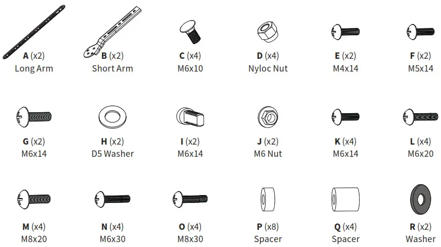
NOTE: SOME HARDWARE INCLUDED MAY NOT BE USED
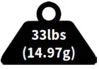 DO NOT EXCEED WEIGHT CAPACITY.
Failure to do so may result in serious injury.
TOOLS NEEDED

ASSEMBLY STEPS
STEP 1
1A-1
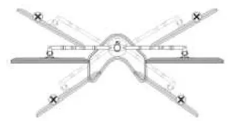
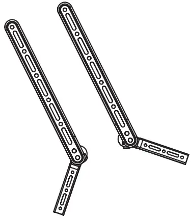
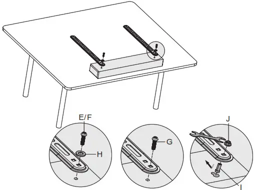
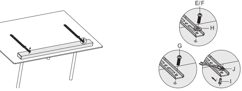
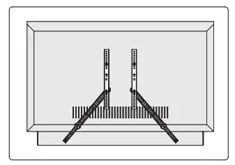
Install long arms (A) to the soundbar. For small M4 or M5 threaded holes, use screws (E or F) and washers (H). For larger M6 threaded holes, use screws (G) without washers. For wall hanging slot holes, insert flat side bolts (I) fully into slots, position square holes in arms over bolts, and tighten with nuts (J).
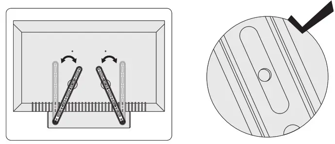
With TV face-down on a table, position soundbar against the edge of TV and align arms with lower VESA mounting holes in TV.
1A-2
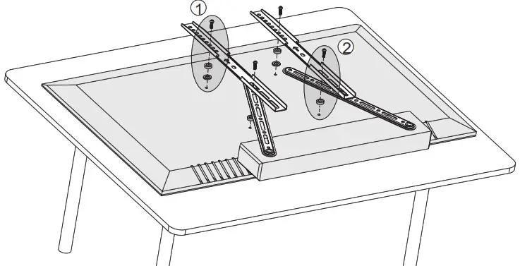
Assemble soundbar with MOUNT-SPSB2 adapter and VESA brackets from your TV mount to TV. Use one of the five following methods, depending on your TV’s requirements. The adapter should be mounted between the TV and the VESA brackets.
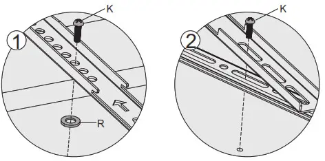
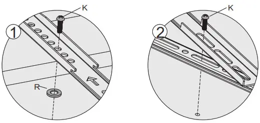
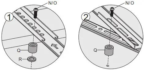
OPTION 1: For top two holes, use spacers (P) between TV and brackets, and secure with screws (K). For lower two holes, secure VESA brackets and adapter using screws (K).
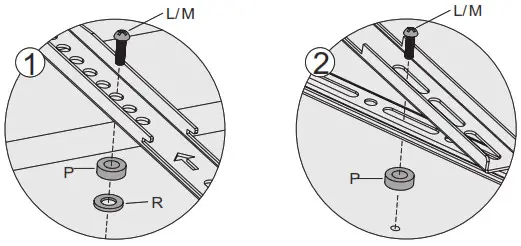
 OPTION 2: For the top two holes, use spacers (P, R) between TV and VESA brackets, and secure them with screws (L, M). For the lower two holes, use a spacer (P) and secure VESA brackets and adapter using screws (L or M).
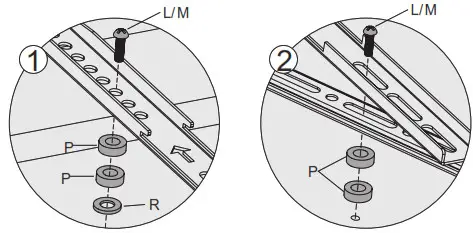
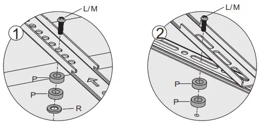
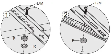 OPTION 3: For top two holes, use spacers (P, R) between TV and VESA brackets, and secure them with screws (L or M). For the lower two holes, use spacers (P) and secure VESA brackets and adapter using screws (L or M).
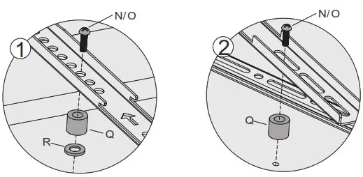
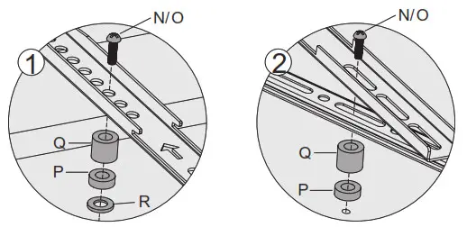
 OPTION 4: For top two holes, use spacers (Q and R) between TV and VESA brackets, and secure with screws (N or O). For the lower two holes, use spacers (Q) and secure VESA brackets and adapter using screws (N or O).
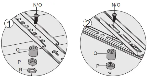
 OPTION 5: For top two holes, use spacers (P, Q, and R) between TV and VESA brackets, and secure with screws (N or O). For the lower two holes, use spacers (P and Q) and secure VESA brackets and adapter using screws (N or O).
The soundbar and TV are now assembled together and are ready to be assembled to the wall. 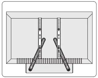
1B-1
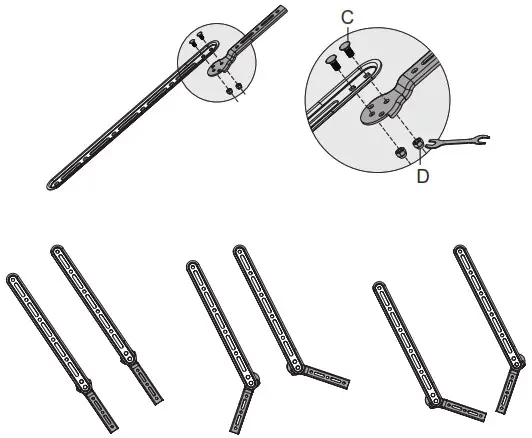
Install short arms (B) to long arms (A) using carriage bolts (C) and ny loc nuts (D). Assemble straight or at an angle, depending on your soundbar and TV’s requirements.
 1B-2
1B-2
Install assembled arms to soundbar. For small M4 or M5 threaded holes, use screws (E or F) and washers (H). For larger M6 threaded holes, use screws (G) without washers. For wall hanging slot holes, insert flat side bolts (I) fully into slots, position square holes in arms over bolts, and tighten with nuts (J).
E/F
 With TV face-down on a table, position soundbar against the edge of TV and align arms with lower VESA mounting holes in TV.
 1B-3
1B-3
Assemble soundbar with adapter and VESA brackets from your TV mount to TV. Use one of the five following methods, depending on your TV’s requirements. The adapter should be mounted between the TV and the VESA brackets.
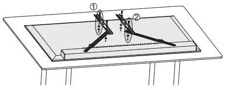
OPTION 1: For top two holes, use spacers (P) between TV and brackets, and secure with screws (K). For lower two holes, secure VESA brackets and adapter using screws (K).
OPTION 2: For the top two holes, use spacers (P, R) between TV and VESA brackets, and secure them with screws (L, M). For lower two holes, use spacer (P) and secure VESA brackets and adapter using screws (L or M).
OPTION 3: For the top two holes, use spacers (P and R) between TV and VESA brackets, and secure them with screws (L or M). For the lower two holes, use spacers (P) and secure VESA brackets and adapter using screws (L or M).
 OPTION 4: For the top two holes, use spacers (Q and R) between TV and VESA brackets, and secure them with screws (N or O). For the lower two holes, use spacers (Q) and secure VESA brackets and adapter using screws (N or O).
OPTION 5: For the top two holes, use spacers (P, Q, and R) between TV and VESA brackets, and secure with screws (N or O). For the lower two holes, use spacers (P and Q) and secure VESA brackets and adapter using screws (N or O).
 The soundbar and TV are now assembled together and are ready to be mounted.
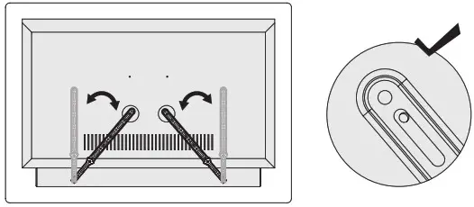
STEP 2
Install TV and soundbar to TV mount.
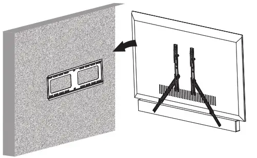 STEP 3
Your TV and soundbar are now ready to use.
 Love your new VIVO setup and want to share?
Tag us in your photo! @vivo_us

Open Monday – Friday 7:00 am – 7:00 pm CST,
our dedicated support team can offer immediate assistance with rapid response times. If any parts are received damaged or defective, please contact us. We are happy to replace parts to ensure you have a fully functioning product.
 [email protected] [email protected] |
AVG. RESPONSE TIME (within office hrs): 1HR 8M – 23% within < 15m – 38% within < 30m – 61% within < 1hr – 83% within < 2hr – 92% within < 3hr |
| www.vivo-us.com Chat live with an agent! |
AVG. RESOLUTION TIME (within office hrs): < 15 M |
| 309-278-5303 |
AVG. RESOLUTION TIME (within office hrs): 5M 4S |
SITE AT: www.vivo-us.com
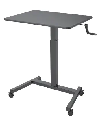
]]>VIVO Black 32” Mobile Presentation Cart
 WARNING!
If you do not understand these directions, or if you have any doubts about the safety of the installation, please call a qualified technician. Check carefully to make sure there are no missing or defective parts. Improper installation may cause damage or serious injury. Do not use this product for any purpose that is not explicitly specified in this manual. Do not exceed weight capacity. We cannot be liable for damage or injury caused by improper mounting, incorrect assembly or inappropriate use.
TIPOVER WARNING
SERIOUS OR FATAL CRUSHING INJURIES CAN OCCUR FROM TIPOVER. TO HELP PREVENT TIPOVER:
- NEVER ALLOW CHILDREN TO CLIMB, STAND, HANG, OR PLAY ON ANY PART OF CART.
- USE TIPOVER RESTRAINT OR ANCHOR CART TO WALL
USE OF TIPOVER RESTRAINTS MAY ONLY REDUCE, BUT NOT ELIMINATE RISK OF TIPOVER.
WARNING: CHOKING HAZARD
SMALL PARTS – NOT FOR CHILDREN UNDER 3 YEARS. ADULT SUPERVISION IS REQUIRED.
PACKAGE CONTENTS
- (x1) Desktop
- (x1) Support Frame
- (x1) Rear Support Bracket
- (x1) Crank Support
- (x1) Crank Handle
- (x1) Column
- (x1) Front Support Bracket
- (x1) Base.

DO NOT EXCEED WEIGHT CAPACITY. Failure to do so may result in serious injury.
ASSEMBLY STEPS
STEP 1
Assemble the base (8) to the column (6) using M6x16 bolts (C) and tighten with the Allen wrench (A). Screw the casters (F) into the base, and tighten using the wrench (G).
STEP 2
Place the support frame (2) on top of the column with the slots facing down and long end forward, making sure the pre-installed bolts on the column insert into the slots. Tighten bolts with Allen wrench (A).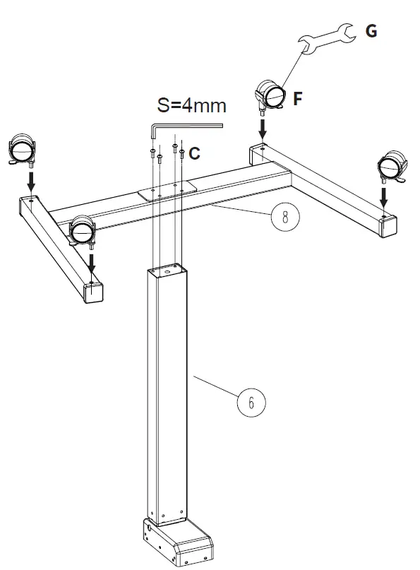
STEP 3
Install the rear support bracket (3) and front support bracket (7) to the support frame (2) using x6 M6x12 bolts (B), and tighten with the Allen wrench (A).
STEP 4
Slide crank support (4) into the frame (3). Secure the crank support to the rear support bracket (3) using x6 M6x8 bolts (D). Tighten with Allen wrench (A) and slide the crank handle (5) into the support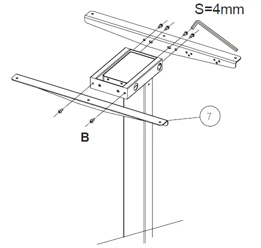
STEP 5
Install the desktop (1) to the top of the frame using x6 M5x14 bolts (E) and tighten with a Phillips screwdriver.
STEP 6
Place monitor, keyboard, mouse and other items on the desk. Raise and lower the desk by turning the crank.
Open Monday – Friday 7:00am – 7:00pm CST,
our dedicated support team can offer immediate assistance with rapid response times. If any parts are received damaged or defective, please contact us. We are happy to replace parts to ensure you have a fully functioning product.
[email protected]
AVG. RESPONSE TIME (within office hrs): 1HR 8M
– 23% within < 15m
– 38% within < 30m
– 61% within < 1hr
– 83% within < 2hr
– 92% within < 3hr
www.vivo-us.com
AVG. RESOLUTION TIME (within office hrs): < 15 M
309-278-5303 AVG. RESOLUTION TIME (within office hrs): 5M 4S.![]()