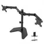

Dual Monitor Desk Mount

SKU: STAND-V002
 Scan the QR code with your mobile device or follow the link for helpful videos and specifications related to this product. https://vivo-us.com/products/stand-v002
GET IN TOUCH | Monday-Friday from 7:00am-7:00pm CST
![]() www.vivo-us.com Chat live with an agent!
www.vivo-us.com Chat live with an agent!
![]() 309-278-5303
309-278-5303
If you do not understand these directions, or if you have any doubts about the safety of the installation, please call a qualified technician. Check carefully to make sure there are no missing or defective parts. Improper installation may cause damage or serious injury. Do not use this product for any purpose that is not explicitly specified in this manual. Do not exceed weight capacity. We cannot be liable for damage or injury caused by improper mounting, incorrect assembly or inappropriate use.
SERIOUS OR FATAL CRUSHING INJURIES CAN OCCUR FROM TIP OVER. TO HELP PREVENT TIP OVER:
- NEVER ALLOW CHILDREN TO CLIMB, STAND, HANG, OR PLAY ON ANY PART OF MONITOR OR STAND.
- USE TIP OVER RESTRAINT OR ANCHOR STAND TO WALL
USE OF TIP OVER RESTRAINTS MAY ONLY REDUCE, BUT NOT ELIMINATE RISK OF TIP OVER.
SMALL PARTS – NOT FOR CHILDREN UNDER 3 YEARS. ADULT SUPERVISION IS REQUIRED.
PACKAGE CONTENTS
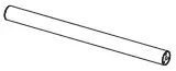
A (x1) Pole
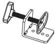
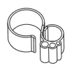
B (x1) Clamp

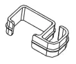
C (x1) Clamp Brace
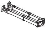
D (x1) Swivel Arm
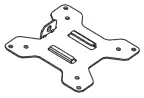
E (x2) VESA Plate

F (x3) M5x14 Bolt

G (x2) M8x12 Bolt

H (x2) Nut

I (x1) M10 Washer

J (x1) Spring Washer

K (x1) Grommet Base Plate
L1 (x1) Wire Clip
L2 (x4) Wire Clip
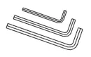
M (x1) Allen Key Set

N (x8) M4x12 Thumbscrew
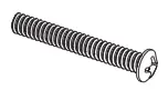
O (x8) M4x30 Bolt
![]()
P (x8) M4 Spacer

Q1 (x1) Soft Pad

Q2 (x1) Soft Pad
NOTE: SOME HARDWARE INCLUDED MAY NOT BE USED
TOOLS NEEDED

Phillips Screwdriver
DO NOT EXCEED WEIGHT CAPACITY.
Failure to do so may result in serious injury.
![]()
22 lbs Per Arm (10kg)
ASSEMBLY STEPS
STEP 1
Option A: Desk Clamp Install
- Install the clamp brace (C) to the pole (A) using x3 M5x14 bolts (F). See Figure 1.
- Attach soft pad (Q1) to the clamp brace (C) , see Figure 2.
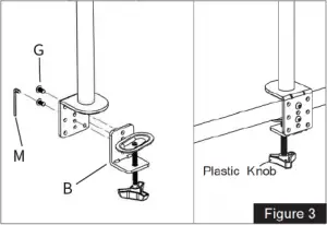
- Install the clamp (B) to the pole assembly according to the thickness of the desktop. The thickness can be changed to 3 positions. Connect using x2 M8x12 bolts (G) and tighten using the Allen wrench (M). Tighten the clamp to the desktop using the plastic knob. See Figure 3.


Option B: Grommet Install
- If desk does not have an existing grommet hole, drill a 3/8″ (10mm) diameter hole at the B2 desired position through the mounting surface.
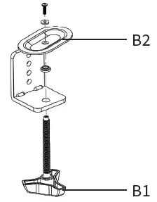
- Completely disassemble clamp (B) into individual parts. Set knob (B1) and clamp plate (B2) aside for later use. The L bracket, bolt, washer and bushing will not be used.
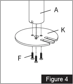
- Install grommet base plate (K) to the pole (A) using x3 M5x14 bolts (F). See Figure 4. B1
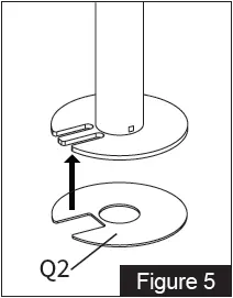
- Attach soft pad (Q2) to the grommet base plate (K), see Figure 5.
- Position pole (A) on the mounting surface and secure using the clamp plate (B2), spring washer (J), M10 washer (I) and knob (B1). See

STEP 2
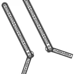
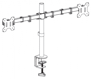
Install swivel arm (D) to the pole (A). Fasten the bolt with supplied Allen wrench (M). Attach the wire clip (L1,L2) to the pole (A) and swivel arm (D).

STEP 3
OPTION A: Flat Back Monitor Attach the VESA plate (E) to the monitor with M4x12 thumbscrews (N).
NOTE: Hand tighten screws to avoid over tightening.

OPTION B: Curved Back Monitor Attach the VESA plate (E) to the monitor with M4x30 bolts (O) and M4 spacers (P).
NOTE: Gently tighten using a screwdriver

STEP 4
Slide the monitor onto the head of swivel arm (D).

Install the security nut (H). Make sure the security nut is installed before you rotate the monitor. For minor height adjustment, use Allen wrench (M).

STEP 5
Tighten the bolt with the supplied Allen wrench (M) to fix the tilt angle.

M To level the monitors, remove the nut (H) and turn the bolt with the Allen wrench (M) to raise or lower the monitor. Replace nut (H) after the adjustment.

STEP 6
Use the supplied Allen wrench set (M) to make any necessary adjustments. Manage cables and store Allen wrenches (M) in wire clip (L1) for future use.


Love your new VIVO setup and want to share? Tag us in your photo! @vivo_us
LAST UPDATED: 03/09/2021 REV1.1
Open Monday – Friday 7:00am – 7:00pm CST, our dedicated support team can offer immediate assistance with rapid response times. If any parts are received damaged or defective, please contact us. We are happy to replace parts to ensure you have a fully functioning product.
![]() [email protected]
[email protected]
![]() www.vivo-us.com
www.vivo-us.com
Chat live with an agent!
![]() 309-278-5303
309-278-5303
AVG. RESPONSE TIME (within office hrs): 1HR 8M – 23% within < 15m – 38% within < 30m – 61% within < 1hr – 83% within < 2hr – 92% within < 3hr
AVG. RESOLUTION TIME (within office hrs): < 15 M
AVG. RESOLUTION TIME (within office hrs): 5M 4S
FOR MORE VIVO PRODUCTS, CHECK OUT OUR WEBSITE AT: www.vivo-us.com