OUTDOOR SPLIT-SYSTEM
AIR CONDITIONING OR HEAT PUMP
MODELS: SINGLE PHASE & THREE PHASE
CONTACT INFORMATION
- Go to the website at www.york.com, then click on Contact Us and follow the instructions.
- Contact us by mail:
Johnson Controls Ducted Systems
Consumer Relations
5005 York Drive
Norman, OK 73069
Read all sections of this manual and keep the manual for future reference.
 WARNING
Cancer and Reproductive Harm – www.P65Warnings.ca.gov
SAFETY
 WARNING
This product must be installed and serviced by a qualified installer or service agency. Improper installation, adjustment, alteration, service or maintenance can cause injury or property damage.
HOW YOUR SYSTEM WORKS
COOLING CYCLE
If your hand is wet and you blow on it, it feels cool because some of the moisture is evaporating and becoming a vapor. This process requires heat. The heat is being taken from your hand, so your hand feels cool. That is what happens with an air conditioner. During the cooling cycle, your system removes heat and humidity from your home and transfers this heat to the outdoor air.
HEATING CYCLE (HEAT PUMPS)
During the heating cycle, your system removes heat and humidity from the outdoor air and transfers this heat to your home. This is possible because even 0°F outdoor air contains a great deal of heat. Remember that your heat pump does not generate much heat, it merely transfers it from one place to another.
System Operation
Your thermostat puts full control of the comfort level in your home at your fingertips. Do not switch your thermostat rapidly ON and OFF or between HEAT to COOL. This could damage your equipment. Always allow at least 5 min between changes.
SETTING THE THERMOSTAT
 CAUTION
The main power to the system must be kept ON at all times to prevent damage to the outdoor unit compressor. If necessary, the thermostat control switch must be used to turn the system OFF. Should the main power be disconnected or interrupted for 8 h or longer, do not attempt to start the system for 8 h after the power is restored to the outdoor unit. If heat is needed during this 8-h period, use emergency heat.
THERMOSTATS
YOUR KEY TO COMFORT
Although thermostats may vary widely in appearance, they are all designed to perform the same basic function: to control the operation of your air conditioning or heat pump system. Regardless of size or shape, each thermostat features a temperature indicator; a dial, arm, or push-button for selection of the required temperature; a fan switch to choose the indoor fan operation; and a comfort switch for you to select the system mode of operation.
Only approved thermostats have been tested and are fully compatible with this equipment. Please be aware that many different thermostats operate on batteries or power
stealing principles. These types of thermostats cannot be supported as trouble-free when used with this product. If your system has been designed to allow both cooling and heating operation, you may have either a manual change-over type or a programmable electronic-type thermostat.
Manual change-over simply means that the comfort switch must be manually positioned every time you wish to switch from the cooling to heating or heating to cooling modes of operation.
Complete operating instruction is provided by the manufacturer for each thermostat. Familiarize yourself with its proper operation to obtain maximum comfort with minimum energy consumption.
The computerized electronic thermostat is actually a sophisticated electronic version of a manual change-over type. This thermostat includes features that allow set-back emperature variations for periods of sleep, or while you are away during the day, and means energy savings for you. The thermostat also features a digital clock.
COOLING ONLY
If your air conditioning system is designed to provide cooling only (AC), with no capability for heating operation (heat pump), a two-stage cooling only thermostat, with a manual, one-position COOL, and OFF comfort switch is all that is required for the system operation.
COOLING AND HEATING (HEAT PUMP)
If your system has been designed to allow both cooling and heating operation, you may have either a manual change-over type or a programmable electronic type thermostat with two stages of cooling and two stages of heat.
MANUAL CHANGE-OVER
Manual change-over simply means that the comfort switch must be manually positioned every time you wish to switch from the cooling to heating or heating to cooling modes of operation.
PROGRAMMABLE ELECTRONIC
THERMOSTATS
The computerized electronic thermostat is actually a sophisticated electronic version of a manual change-over type. This thermostat includes features that allow set-back emperature variations for periods of sleep, or while you are away during the day, and means energy savings for you. The thermostat also features a digital clock.
FAN OPERATION SELECTION
A multi-position fan switch allows you to choose the type of fan operation of the indoor fan.
AUTO
With the thermostat fan switch set to AUTO, the fan runs intermittently as required for either heating or cooling. This position provides the lowest operating cost. If you purchased one of our thermostats, they have an Intelligent fan mode that continually circulates the air during occupied modes or when you are at home and can cycle the fan during unoccupied mode or during the night while you sleep to further conserve energy.
ON
CONTINUOUS FAN OPERATION: With the thermostat fan switch set to ON, the indoor fan does not shut off. However, the cooling (AC) or heating (heat pump) systems still operate as required by room temperatures. This provides continuous air filtering and more even temperature distribution to all conditioned spaces.
FAN ONLY OPERATION: On moderate days, usually during spring and fall, when neither heating nor cooling is required, you may want to run only the fan to ventilate, circulate, and filter the air in your home or building. Set the comfort control switch to OFF and the fan switch to ON. Be sure to return the switches to their original positions for normal operation.
START-UP
The maximum and minimum conditions for operation must be observed to assure a system that gives maximum performance with minimum service.
TABLE 1: Application Limitations¹
| Model | Air Temperature an Outdoor Co I (°F) | Air Temperature at Indoor Coil (°F) | ||||||
| Minimum | Maximum | Minimum | Maximum | |||||
| DB Cool | DB Heat | DB Cool | DB Heat | WEI Cool | DB Heat | WB Cool | DB Heat | |
| 10 All 13 SEER AC | 55 | – | 115 | 57 | – | 72 | – | |
| 3$ All 13 and 17 SEER AC | 55 | – | 125 | – | 57 | – | 72 | – |
| All 13 SEER Horizontal AC | 55 | – | 115 | – | 57 | – | 72 | – |
| All 14 SEER Horizontal AC | 55 | – | 120 | – | 57 | – | 72 | – |
| All 14+ SEER AC and HP | 55 | -10 | 125 | 75 | 57 | sal | 72 | 80 |
| All Inverter AC and HP | 50 | -20 | 125 | 75 | 57 | 50 | 72 | 80 |
| All 2-Stage AC | 3 5-542 553 |
– | 125 | – | 57 | – | 72 | – |
| All 2-Stage HP | 35-54 | -20 | 125 | 75 | 57 | 50 | 72 | 80 |
- Operation below this temperature is permissible for a short period of time during morning warm-up.
- With Crankcase Heater Kit.
- Without Crankcase Heater Kit.
The comfort control switch is assumed to be in the OFF position. If the main power supply to the outdoor and indoor units is off, turn the appropriate disconnects
to the ON position. Place the system into operation as follows.
- Set temperature adjustment to the required temperature on your thermostat.
COOLING – The higher the setting, the lower the amount of energy consumed. Federal Guidelines recommend a setting of 8°F.
HEATING -The lower the setting, the lower the amount of energy consumed. Federal guidelines recommend a setting of 65°F or lower.
NOTICE
If your cooling and heating temperature adjustments are separate, be sure to set both. - After considering Fan Operation Selection (see page 2), select and set the fan operation mode you desire.
- Move the comfort control switch to the required mode of operation (Cooling or Heating) found on your particular thermostat.
POWER FAILURE
SYSTEM OPERATION
MANUAL CHANGE-OVER THERMOSTAT
COOLING YOUR HOME: With the comfort control switch in the COOL position, the system operates as follows: When the indoor temperature rises above the level indicated by the temperature adjustment setting, the system starts. The outdoor unit operates and the indoor fan circulates the cooled, filtered air. When the room temperature is lowered to the setting selected, the system shuts off.
HEATING YOUR HOME: If your system includes a heating unit and the comfort control switch is in the HEAT position, the system operates as follows: When the indoor
temperature drops below the level indicated by the temperature adjustment setting, the system starts. The heating system operates and the indoor fan circulates the filtered air.
When the room temperature rises to the setting selected, the system shuts off.
Whether heating or cooling, the fan continues to operate if the fan the switch was set in the ON or Intelligent position. The AUTO setting on the fan switch allows the fan to shut off when your system does.
ELECTRONIC THERMOSTAT
The computerized electronic thermostat, when programmed, functions automatically to operate the system as follows: When the indoor temperature rises above the higher (COOL) setting, the outdoor unit operates and the indoor fan circulates the cooled, filtered air. When the room temperature is lowered to the selected level, the system shuts off. The indoor fan either shuts off or runs continuously, depending upon your choice of the fan switch set. When the indoor temperature drops below the lower (HEAT) setting, the heating system operates, and the indoor fan circulates the heated, filtered air. When the indoor temperature rises to the selected setting, the system shuts off. The indoor fan either shuts off or runs continuously, depending upon your choice of the fan switch set.
TO MAXIMIZE OPERATING EFFICIENCY
HEATING CONSERVATION
For the most efficient operation, keep storm windows and doors closed all year long. They not only help insulate against heat and cold, but they also keep out dirt, pollen, and noise. Closing drapes at night, keeping fireplace dampers closed when not in use, and running exhaust fans only when necessary helps you to retain the air you have already paid to heat.
Keep lamps, televisions, or other heat-producing sources away from the thermostat. The thermostat senses this extra heat and is not able to maintain the inside temperature to the required comfort level.
COOLING CONSERVATION
To comfortably cool your home, your air conditioner must remove both heat and humidity. Do not turn your system off even if you are away all day. On a hot day, your system may have to operate between 8 h to 12 h to reduce the temperature in your home to a normal comfort level.
Keep windows closed after sundown. While the outdoor temperature at night may be lower than indoors, the air is generally loaded with moisture, which is soaked up by furniture, carpets, and fabrics. This moisture must be removed when you restart your system.
The hotter the outside temperature, the greater the load on your system. Therefore, do not be alarmed when your system continues to run after the sun has set on a hot day. Heat is stored in your outside walls during the day and continues to flow into your home for several hours after sunset.
Use your kitchen exhaust fan when cooking. One surface burner on HIGH requires one ton of cooling. Turn on your bathroom exhaust fan while showering to remove humidity. However, exhaust fans must not be run excessively as this increases efficiency by removing conditioned air.
You can also help your system in the summer by closing drapes or blinds and by lowering awnings on windows that get direct sunlight.
CARE OF SYSTEM
It is strongly recommended that regular periodic preventative maintenance be performed on this equipment. The person most familiar with the equipment in your heating, ventilation and air-conditioning (HVAC) system is a dealer. The dealer can ensure your maintenance program meets the conditions of the Limited Warranty (see page 5), maximize the efficiency of the equipment, and service your unit within the federally mandated guidelines with regard to unlawful discharge of refrigerants into the atmosphere.
COIL CARE
Keep the outdoor unit free of foliage, grass clippings, leaves, paper, and any other material which could restrict the proper airflow in and out of the unit. The coil may be vacuumed to remove any debris from between the fins. If the coil becomes excessively dirty, turn the main disconnect switch to OFF and wash the coil with your garden hose. Avoid getting water into the fan motor and control box. Flush dirt from the base pan after cleaning the coil.
SERVICE CALLS
There are a few instances where the user can avoid unnecessary service calls. If the unit stops functioning correctly, check the following items before calling your servicing dealer:
- Indoor section for the dirty filter.
- Outdoor section for leaf or debris blockage. Eliminate the problem, turn off the thermostat for 10 s and attempt a start. Wait 5 min. If the system does not start, call your servicing dealer.
WARNING
Your system contains environmentally friendly refrigerant R-410A, which operates at high pressures. You may be in danger if you try to make an attempt to repair your unit. Please contact your local dealer.
FILTER CARE
Inspect the air filters at least once a month. If they are dirty, wash reusable filters with a mild detergent per the manufacturer’s recommendations. Replace disposable filters with new filters. Install the clean filters with the airflow arrow in the same direction as the airflow in your duct. Filters must be clean to assure maximum efficiency and adequate air circulation.
CLEARANCES
The minimum clearances shown below must be maintained should any patio or yard improvements be done around the outdoor unit.
TABLE 2: Outdoor Unit Clearances
| Model | Coil Clearance Area (in.) | Overhead Clearance (In.) | Service Panel Access (In.) | Unit to Unit Distance (in.) |
| All 13 SEER AC | 10 | 48 | 18 | 24 |
| 13 and 14 SEER Horizontal AC | 6 | N/A | 18 | 181 |
| All 14+ SEER AC & HP | 10 | 48 | 18-24 2 | 24 |
| All inverter AC & HP | 10 | 48 | 18 | 24 |
- Distance is for Coil face to Coil face installations only. It is not recommended to install discharge air of one unit towards the inlet air side of another in multi-unit installations.
- Refer to the installation manual for specific model details.
PARTS INFORMATION
Replacement parts are available from a local contractor/dealer.
EXTENDED WARRANTY
Special warranty packages (called YORK Care Performance Promise) are available through your contractor. These packages reduce the potential cost of service calls following the first year of operation on your cooling (or heating/cooling) system.
SOME EFFICIENCY DOS AND DO HOTS
Do not heat or cool unused household area. Reduce supply and return airflow to a minimum in areas that are not living spaces. such as storage rooms, garages. or basements.
Do not be a thermostat jigger. Moving your thermostat setting does not make your system heat or cool any faster. Adjust your thermostat to a comfortable setting and leave it there.
Do not restrict air circulation. Placing furniture. rugs and other objects in such a way that they interfere with air vents make your system work harder to achieve a comfortable temperature level. This requires more energy. which means a greater cost to you.
Do not locate lamps or other heat-producing appliances such as radios, TVs, or heaters near your thermostat. The heat from these items gives your thermostat false information about the temperature in the room.
Do select a comfortable thermostat setting, but keep in mind that moderation in temperature selection saves energy.
Do turn on your kitchen exhaust fan when cooking and your bathroom exhaust fan when showering. Also. make sure your clothes dryer is correctly vented. If you neglect these items, this may create an excess heat and humidity condition, causing your air conditioning system to run longer.
Do set your thermostat a few degrees lower than normal for several hours before entertaining a large group of people in a relatively small area. People give off a considerable amount of heat and moisture in a closed area.
Do keep drapes and Venetian blinds closed when practical. These items provide insulation against heat loss/gain.
Do contact a qualified service person to make repairs or adjustments to your system.
CHARACTERISTICS OF HEAT PUMPS
A CONSTANT NEAT
Heat pumps have a noticeable cooler supply air temperature than furnaces. The common practice of oversizing furnaces contributes to an off-and-on again operation with short blasts of hot supply air. The heat pump system is sized more closely to the heating needs of your home. Heat is supplied at a lower temperature over a longer period of time to provide a more constant heat, and it may give you the impression that your system never stops running.
WATER RUN-OFF
During the heating cycle, in mild weather, you may notice water running off the outdoor coil. Moisture from the air is condensed on the outside surface of the coil where it gathers and runs off. This is no need for an alarm and your unit is not leaking.
OUTDOOR COIL DEFROSTING
In certain outdoor conditions (low temperature, high humidity), frost may build up on the coil of the outdoor unit. In order to maintain heating efficiency. the system automatically defrosts itself. Steam rising from the outdoor unit is normal and is an indication of proper operation. The vapor cloud only lasts for a few minutes. When the defrost cycle is completed. the system automatically switches back to heating. Auxiliary heat is automatically energized to maintain comfort during defrosting.
Limited Warranty
Residential Split Air Conditioning & Heat Pump Condensing Units
WARRANTY TERMS: Johnson Controls Unitary Products (“Company”) warrants this product to be free from defects in factory workmanship and material under normal use and service and will at its option, repair or replace defective parts without charge, subject to the exclusions below and according to the terms outlined in this warranty. The company reserves the right, at its sole discretion, to provide an equivalent complete replacement unit in place of repair parts. Alternatively, Company may at its option, offer a replacement price allowance to be applied toward the purchase of a new unit offered by the Company. The exact allowance amount will be determined at the discretion of the Company, based upon availability, age of existing equipment, and current market conditions, but excluding items as ductwork, wiring, piping, and installation costs. The warranty period for obtaining repaired or replacement parts, or an allowance shall not extend beyond the original warranty period as stated below. In addition, if a replacement unit is provided by Company, the warranty period for the complete replacement unit is limited to the remainder of the original warranty period.
This warranty covers only equipment described by the Product Model Number and Unit Serial Number on the equipment or listed on the Warranty Registration Card, and applies only to products installed in the United States, Canada, or Puerto Rico. The company shall have no responsibility for installation, service, shipping, handling or other costs or charges, except as otherwise provided in this warranty. Tampering, altering, defacing, or removing the product serial number will serve to void this warranty. This warranty extends only to the original consumer purchaser and is nontransferable.
For this warranty to apply, the product must be installed according to Company recommendations and specifications, and in accordance with all local, state, and national codes; and the product or residence must not be removed from its place of original installation. This warranty does not apply to any unit sold over the Internet, by telephone or other electronic means unless the dealer that buys or sells a unit over the Internet, by telephone or other electronic means also installs the unit. In the absence of a recorded Warranty Registration Card, the warranty period will begin upon product shipment from Company. If you are unaware of the effective warranty date, contact Company at (877) 874-7378 or www.upgoroductregistration.com.
FOR PRODUCT REGISTRATION: For your benefit and protection, register your product with Company promptly after installation. This will initiate the warranty period and allow us to contact you, should it become necessary. You can register your product online at www.upgproductregistration.com or by returning the Warranty Registration Card on the back page of this packet.
Product Model Number: ____________________________________
Installation Date: __________________________________________
Unit Serial Number: _______________________________________
Installing Dealer: __________________________________________
FOR WARRANTY SERVICE OR REPAIR: Notify your Installing Dealer or a Participating Dealer, preferably in writing, as soon as possible after the discovery of the problem. Be sure to include the Product Model Number, Unit Serial Number, Installation Date, and a description of the problem. You may find the Installing Dealers name on this page or on the equipment, and you can locate Participating Dealers online at www.yorkupg.com.
If a Dealer response is not received within a reasonable amount of time, notify Company at: Johnson Controls Unitary Products, Consumer Relations, 5005 York Drive, Norman, OK 73069 or by telephone at (877) 874-7378. All warranty service or repair will be performed during regular business hours, Monday through Friday 9:00 AM – 5:00 PM. Service requests sent to Company without prior Dealer contact will be referred back to a Participating Dealer. Because this process takes time, it is in the best interest of the Consumer to contact a Participating Dealer directly.
WARRANTY PERIOD: The warranty period in years, depending on the part, is as shown in the chart below.
| CONDENSING UNITS | ||
| CONDENSING UNITS | COMPRESSOR | PARTS |
| R-407C Models: GAW14L | 5 years | 5 years |
| R-410A Models: RAC13L, RAC14L, RAW14L, REP14L, RHP14L, RHP16L | 5 or 10 years | 5 or 10 years |
| R-410A Models: YCD, TC3B, YCE, TC4B, YCG, CC7B, TC7B, YCS, TW4B, YFD, TF3B, YFE, TF4B, YFK, CC17, TC17, TCD*, TCG*, TCHD*, TCHE*, YEE, TE4B, YHE, TE-148, YHG, CH6B, TH6B, YHM, CH16, TH16, THE* | 10 years | 5 or 10 years |
| R-410A Models: YXT, AC19B, HC19B, YZT, AL19B, HL19B | 10 years or Lifetime* | 5 or 10 years |
NOTES:
*All 3 phase models (with 31, 41, or 51 voltage codes) have a 5-year compressor and 1-year parts warranty and are not eligible for a 10-year parts warranty. To qualify for the to Extended 10-year parts warranty or the tt Extended 10-year compressor warranty or t Lifetime compressor warranty, the unit must be registered online at www.upgnroductregistration.com within 90 days of installation for replacement units or within 90 days of closing for new home construction. In some states, registration is not required, but proof of installation is required.
MAINTENANCE: Company strongly recommends regular periodic preventive maintenance on this equipment. The person most familiar with the equipment in your HVAC system is a Participating Dealer. The Participating Dealer can ensure that your maintenance program meets the “Company Warranty” conditions, maximize the equipment efficiency, and service your unit within the mandated guidelines with regard to unlawful discharge of refrigerants into the atmosphere. For additional buyer protection, Residential Home Comfort Plans are available from a Participating Dealer. These plans provide you with additional years of warranty service protection including labor charges. Home Comfort Plans must be purchased within one (1) year from the date the equipment was installed.
EXCLUSIONS: This warranty does not cover any:
- Shipping, labor, or material charges or damages resulting from transportation, installation, or servicing.
- Damage or repairs are required as a consequence of mishandling, faulty installation, misapplication, abuse, improper servicing, unauthorized alteration, or improper operation.
- Damages or failure to start resulting from improper voltage conditions, blown fuses, open circuit breakers, or other inadequacy or interruption of electrical service or fuel supply.
- Fuses, either internal or external to the product.
- Labor or other costs incurred for diagnosing, repairing, removing, installing, shipping, servicing, or handling of either defective parts or replacement parts.
- Products were removed from their original location for reinstallation purposes.
- Damages resulting from accident, abuse, fire, flood, alteration, or acts of God.
- Damages resulting from the use of the product in a corrosive atmosphere.
- Normal maintenance or damages resulting from failure to perform normal maintenance, as outlined in the installation and servicing instructions or owners manual.
- Cleaning or replacement of filters, nozzles, or orifices.
- Damages resulting from operation with an inadequate supply of air or water; Damages resulting from failure to properly and regularly clean air and/ or water side of condenser and evaporator.
- Damages resulting from (I) freezing of condensed water or condensate; (II) inadequate or interrupted water supply; (Ill) use of corrosive water; (IV) fouling or restriction of the water circuit by foreign material or like causes.
- Damages caused by improper parts, components or accessories not suitable for use in or with the unit. For a list of parts that are known to be compatible please reference the equipment renewal parts list, contact a Participating Dealer for assistance, or call 1-877-874-7378.
- Electricity or fuel costs, or increases in fuel or electric costs, for any reason including additional or unusual use of supplemental electric heat.
This warranty is in lieu of all other express warranties. All implied warranties, including the implied warranty of merchantability and fitness for a particular purpose, are limited in duration to the actual warranty period applicable to the part. Some states do not allow the disclaimer of implied warranties, so the above disclaimer may not apply to you. In addition, some states do not allow limitations on how long an implied warranty lasts, so the above limitation may not apply to you. In no event, whether as a result of a breach of warranty or contract, tort (including negligence), strict liability, or otherwise, shall Company be liable for special, incidental, or consequential damages or expenses, including but not limited to loss of use of the equipment or associated equipment, lost revenues or profits, cost of substitute equipment, or cost of fuel or electricity.
The above limitations shall inure to the benefit of the Company’s suppliers and subcontractors. The above limitation on consequential damages shall not apply to injuries to persons in the case of consumer goods. The company does not assume, or authorize any other person to assume for Company, any other liability for the sale of this product. Some states do not allow the exclusion or limitation of incidental or consequential damages, so the above limitation may not apply to you. This warranty gives you specific legal rights. You may also have other rights which vary from state to state.
Subject to change without notice. Published in the U.S.A.
Copyright © 2021 by Johnson Controls, Inc. All rights reserved.
1183508-UUM-O-0121
Supersedes: 1183508-UUM-N-0120
York International Corp.
5005 York Drive
Norman, OK 73069
YORK DRCR Wireless Remote Controller Manual
Important Notice
- Johnson Controls, Inc. pursues a policy of continuing improvement in design and performance in its products. As such, Johnson Controls, Inc. reserves the right to make changes at any time without prior notice.
- Johnson Controls, Inc. cannot anticipate every possible circumstance that might involve a potential hazard.
- This inverter air conditioning unit is designed for standard air conditioning applications only. Do not use this unit for anything other than the purposes for which it was intended for.
- The installer and system specialist should safeguard against leakage in accordance with local pipefitters and electrical codes. The following standards may be applicable if local regulations are not available. International Organization for Standardization: (ISO 5149 or European Standard, EN 378). No part of this manual may be reproduced in any way without the expressed written consent of Johnson Controls, Inc.
- This air conditioning accessory will be operated and serviced in the United States of America and comes with all required Safety, Danger, and Caution warnings.
- If you have questions, please contact your distributor or dealer.
- This manual provides common descriptions, basic and advanced information to maintain and service this air conditioning unit which you operate, as well for other models.
- This air conditioning unit has been designed for a specific temperature range. For optimum performance and long life, operate this unit within range limits.
- This manual should be considered as a permanent part of the air conditioning equipment and should remain with the air conditioning equipment.
Product Inspection upon Arrival
- Upon receiving this product, inspect it for any damages incurred in transit. Claims for damage, either apparent or concealed, should be filed immediately with the shipping company.
- Check the model number, electrical characteristics (power supply, voltage, and frequency rating), and any accessories to determine if they agree with the purchase order.
- The standard utilization for this unit is explained in these instructions. Use of this equipment for purposes other than what it was designed for is not recommended.
- Please contact your local agent or contractor as any issues involving installation, performance, or maintenance arise. Liability does not cover defects originating from unauthorized modifications performed by a customer without the written consent of Johnson Controls, Inc. Performing any mechanical alterations on this product without the consent of the manufacturer will render your warranty null and void.
SAFETY MESSAGES
WARNING: Indicates a hazardous situation that, if not avoided, could result in death or serious injury.
CAUTION: Indicates a hazardous situation that, if not avoided, could result in minor or moderate injury.
NOTICE: Indicates information considered important, but not hazard-related (e.g. messages relating to property damage).
GENERAL PRECAUTIONS
Warning: To reduce the risk of serious injury or death, read these instructions thoroughly and follow all warnings or cautions included in all manuals that accompanied this product and the indoor and outdoor units.
- This system, including this controller, should be installed by personnel certified by Johnson Controls, Inc. Personnel must be qualified according to local, state and national building and safety codes and regulations. Incorrect installation could cause leaks, electric shock, fire or explosion.
- Use appropriate personal protective equipment, such as gloves and protective goggles and electrical protection equipment and tools suited for electrical operation purposes.
- Do not stand on or put any material on the controller.
- When installing the controller cabling to the units, do not touch or adjust any safety devices inside the indoor or outdoor units. All safety features, disengagement, and interlocks must be in place and functioning correctly before the equipment is put into operation. If these devices are improperly adjusted or tampered with in any way, a serious accident can occur. Never bypass or jump out any safety device.
- Use only Johnson Controls recommended or provided as standardized or replacement parts.
- Johnson Controls shall not assume any liability for injuries or damage caused by not following steps outlined or described in this manual. Unauthorized modifications to Johnson Controls products are prohibited as they…
- may create hazards that could result in death, serious injury or equipment damage.
- will void product warranties.
- may invalidate product regulatory certifications.
- may violate OSHA standards.
NOTICE: Take the following precautions to reduce the risk of property damage
- Do not touch the main circuit board or electronic components in the controller or remote devices. Also, make sure that dust and/or steam does not accumulate on the circuit board.
- Locate the wireless zone controller at a distance of at least 3 ft. (approx. 1m) between the indoor unit and electric lighting. Otherwise, the receiver part of the unit may have difficulty receiving operation commands.
- If the wired zone controller is installed in a location where electromagnetic radiation is generated, make sure that the wired zone controller is shielded and cables are sleeved inside conduit tubing.
- If there is a source of electrical interference near the power source, install noise suppression equipment (filter).
- During the run test, check the unit’s operating temperature. If the unit is used in an environment where the temperature exceeds the operation boundary, it may cause severe damage. Check the operational temperature boundary in the manual. If there is no specified temperature, use the unit within the operational temperature boundary of 35°~104°F (0~40°C).
- Read installation and appropriate user manuals for connection with PC or peripheral devices. If a warning window appears on PC, the product stops, does not work properly or works intermittently, immediately stop using the equipment.
INSTALLATION PRECAUTIONS
To reduce the risk of serious injury or death, the following installation precautions must be followed:
- If the remote sensors are not used with this controller then do not install this controller…
- in a room where there is no thermostat.
- where the unit is exposed to direct sunshine.
- where the unit will be in close proximity to a heat source.
- where hot/cold air from the outdoors, or a draft from elsewhere (such as air vents, diffusers or grilles) can affect air circulation.
- in areas with poor air circulation and ventilation.
- Perform the run test using the controller to ensure normal operation. Safety guards, shields, barriers, covers, and protective devices must be in place while the compressor/unit is operating. During the run test, keep fingers and clothing away from any moving parts.
After installation work for the system has been completed, explain the “Safety Precautions,” use, and maintenance of the unit to the customer according to the information in all manuals that accompanied the system. All manuals and warranty information must be given to the user or left near the Indoor Unit.
ELECTRICAL PRECAUTIONS
Take the following precautions to reduce the risk of electric shock, fire or explosion resulting in serious injury or death:
- Only use electrical protection equipment and tools suited for this installation.
- Insulate the wired zone controller against moisture and temperature extremes.
- Use specified cables between units and the controller.
- The polarity of the input terminals is important, so be sure to match the polarity when using contacts that have polarity.
- Highly dangerous electrical voltages may be used in this system. Carefully refer to the wiring diagram and these instructions when wiring. Improper connections and inadequate grounding can cause serious injury or death.
- Before installing the controller or remote devices, ensure that the indoor and outdoor unit operation has been stopped. Further, be sure to wait at least five minutes before turning off the main power switch to the indoor or outdoor units. Otherwise, water leakage or electrical breakdown may result.
- Do not open the service cover or access panel to the indoor or outdoor units without turning OFF the main power supply. Before connecting or servicing the controller or cables to indoor or outdoor units, open and tag all disconnect switches. Never assume electrical power is disconnected. Check with meter and equipment.
- Use an exclusive power supply at the controller’s rated voltage.
- Be sure to install circuit breakers (ground fault interrupter, isolating switch, molded case circuit breaker, and so forth) with the specified capacity. Ensure that the wiring terminals are tightened securely to recommended torque specifications.
- This equipment can be installed with a Ground Fault Circuit Breaker (GFCI), which is a recognized measure for added protection to a properly grounded unit. Install appropriate sized breakers/fuses / overcurrent protection switches, and wiring in accordance with local, state and NEC codes and requirements. The equipment installer is responsible for understanding and abiding by applicable codes and requirements.
- Clamp electrical wires securely with a cable clamp after all wiring is connected to the terminal block. In addition, run wires securely through the wiring access channel.
- When installing the power lines, do not apply tension to the cables. Secure the suspended cables at regular intervals, but not too tightly.
- Make sure that the terminals do not come into contact with the surface of the electrical box. If the terminals are too close to the surface, it may lead to failures at the terminal connection.
- Do not clean with, or pour water, into the controller as it could cause electric shock and/or damage the unit. Do not use strong detergent such as a solvent. Clean with a soft cloth.
- Check that the ground wire is securely connected. Do not connect ground wiring to gas piping, water piping, lighting conductor, or telephone ground wiring.
User Notice
| CAUTION ! |
| ① Make sure there is no obstruction between the wireless remote controller and the signal
receiver. |
| ② The signal receiving distance of the wireless remote controller can be up to 32.8 feet. |
| ③ Never drop or throw the wireless remote controller. |
| ④ Never allow any liquid to touch the wireless remote controller. |
| ⑤ Never expose the wireless remote controller to direct sunlight or where it is very hot. |
| ⑥ This is a general remote control that can be used for multiple types (functions) of air conditioners. |
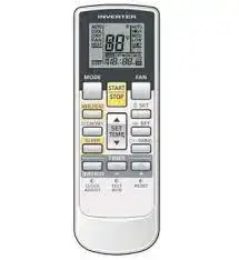
Control Panel of the Wireless Remote Controller

| No. | Name | Function Description |
| 1 | Signal
Transmitter |
● Signal transmitter |
| 2 | ON/OFF
Button |
● Press this button, and the unit will be turned on; press it once more, and the unit will be turned off. When turning off the unit, the Sleep function will
be canceled, but preset time is still enabled. |
| 3 | MODE
Button |
● Pressing this button, Auto, Cool, Dry, Fan, and Heat mode can be selected sequentially. Auto mode is the default after powered on. Under the Auto mode, the setting temperature will not be displayed. Under the Heat mode, the initial value is 82°F (28°C). Under other modes, the initial value is 77°F (25°C).
AUTO ; COOL; DRY; FAN; HEAT (only for cooling and heating unit) |
| 4 | – Button | ● Preset temperature can be decreased by pressing this button. Pressing and holding this button for more than 2 seconds will decrease the preset temperature rapidly. When the button is released, the setting will be transmitted. The temperature adjustment is unavailable under the Auto mode, but the order can be sent by pressing this button. Centigrade setting range: 16°- 30°. Fahrenheit scale setting range: 61°- 86°. |
| + Button | ● Preset temperature can be increased by pressing this button. Pressing and holding this button for more than 2 seconds will increase the preset temperature rapidly. When the button is released, the setting will be transmitted. The temperature adjustment is unavailable under the Auto mode, but the order can be sent by pressing this button. Centigrade setting range: 16°- 30°; Fahrenheit scale setting range: 61°-86°. | |
| 5 | FAN Button | ● By pressing this button, Auto, Low, Middle, High speed is sequentially
selected. After powered on, Auto fan speed is the default. ● AUTO Low speed Middle speed High speed Note: Under the DRY mode, the fan will be kept running at the low speed and the fan speed isn’t adjustable. |
| 6 | SWING UP/DOWN
Button |
● Press this button to set up the swing angle, which sequentially changes as shown.
● When the guide louver starts to swing up and down, if SWING funtions is canceled, the air guide louver will stop and remains at the current position. ● indicates the guide louver swings up and down among those five directions.(Simplified SWING function applicable for some fan coil units. When the wireless remote controller is energized initially with the unit under the OFF status, it should be set by pressing the + button and the SWING button simultaneously, with the symbol blinking twice. Then, after the unit is turned on, this function can be activated by pressing the SWING button, with the displayed symbol indicating swing function is on and without this displayed symbol indicating swing function is off.) |
| 7 | CLOCK
Button |
● By pressing this button, the clock is allowed to be set, with blinking, and then press the +/- button to adjust the clock within 5 seconds. If the +/- button is pressed down continuously for more than 2 seconds, the clock setting will be increased or decreased by 10 minutes every
0.5 seconds. After that, another press on the CLOCK button accepts the setting. 12:00 is the default, when the wireless remote controller is energized. |
| 8 | TIMER ON
Button |
● When TIMER ON is activated, ON will blink while the symbol will disappear. Within 5 seconds, set the ON time by pressing the +/-
button. Each press will make the time increase or decrease by 1 minute. The time can also be set by pressing and holding the +/- button. Within the first 2.5 seconds, the time will increase/ decrease quickly by minute, and in the next 2.5 seconds, the time will increase/decrease by 10 minutes. After the desired time value is set, press TIME ON again to conform the setting within 5 seconds. After that, another press of TIMER ON will cancel the setting. Prior to this setting, the clock should be set to the actual time. |
| 9 | X-FAN
Button |
● Pressing this button can activate or deactivate the X-FAN function.
In Cool or Dry mode, by pressing this button,if ” ” is displayed, it indicates the X-FAN function is activated. By repressing this button, if ” ” disappears, it indicates the X-FAN function is deactivated. Upon initial power up, the X-FAN function is defaulted to OFF. If the unit is turned off, X-FAN can be deactivated but can’t be activated. |
| 10 | TEMP
Button |
● Pr essing this button will toggle the temperature displayed on the remote between the indoor setting temperature and the indoor temperature.
● Indoor setting temperature is default after the indoor unit is initially powered up. ● By pressing the TEMP button, when the temperature symbol is displayed, the indoor setting temperature is displayed. When is displayed, the indoor temperature is displayed. When is displayed, there is an error with the temperature sensor. If a TEMP signal from another remote is received, the preset temperature will be displayed. After 5 seconds, the display will return to the indoor temperature. (This function is not applicable to all models.) |
| 11 | TIMER
OFF Button |
● By pressing this button, the TIMER OFF settting can be set with the same setting method as that of the TIMER ON, in which case the OFF symbol blinks. |
| 12 | TURBO
Button |
● In the Cool or Heat mode, pressing this button can activate or deactivate the TURBO function.When the TURBO fucntion is activated, its symbol will be displayed; when the running mode or the fan speed is changed, this function will be canceled automatically.(This function is
not applicable to all models). |
| 13 | SLEEP
Button |
● By pressing this button, Sleep On and Sleep Off can be selected. Upon initial power up, the SLEEP function is defaulted to OFF. Once the unit is turned off, the Sleep function is canceled. When Sleep is set to On, the symbol will display. |
| 14 | LIGHT
Button |
● Press this button to toggle the display backlight ON/OFF.
LIGHT is set to on, the icon will be displayed and the indicating light in the display will be on. When the LIGHT is set to off, the icon will not be displayed and the indicating light in the display will be off. |
Additional Functions
- X-FAN function (This function is applicable to select models.)
This function is used to keep the fan running on the indoor unit to remove moisture from the evaporator coil.- With X-FAN function ON: After turning off the unit by pressing the ON/OFF button, the indoor fan will continue running for several minutes at low speed. In this period, press the X-FAN button to stop the indoor fan.
- With X-FAN function OFF: After turning off the unit by pressing the ON/OFF button, the unit will shut off immediately..
- TURBO function (This function is applicable to select models)
If the TURBO function is activated, the unit will run at high fan speed to perform cooling or heating so that the ambient temperature will approach the preset temperature more quickly. - Lock
Press + and – buttons simultaneously to lock or unlock the keyboard. If the wireless remote controller is locked, the icon will be displayed, in which case, any button press will result in no response but with the icon blinking three times. If the keyboard is unlocked, the blinking icon will disappear.
● SWING UP/DOWN- Press the Swing Up/Down button for more than 2 seconds and then the louver will swing up and down. After releasing the button, the louver will stop swinging and keep the current position.
- When the louver starts swinging, by pressing the Swing Up/Down button 2 seconds later, the louver will stop swinging. By pressing the Swing Up/Down button within 2 seconds, the louver will continue swinging.
- Change Over Switch between Fahrenheit and Centigrade
Under the OFF state of the unit, press MODE and “-” buttons simultaneously to switch between °C and
Replacement of Batteries
- Slightly press the place with along the arrowhead direction and push the back cover of the wireless remote controller.
- Take out the used batteries.
- Insert two new AAA 1.5V dry cell batteries and pay attention to their polarity.
- Put back the cover of the wireless remote controller.
Notes!
- When changing the batteries, do not use used or different-type batteries. Otherwise, it will cause a malfunction to the wireless remote controller.
- If the wireless remote controller will not be used for a long time, please take the batteries out. Battery discharge can damage the wireless remote controller.
- The operation should be within the signal receiving range.
- It should be placed three feet away from a TV set or stereo.
- If the wireless remote controller can not operate normally, please take batteries out for 30s. If the anomaly persists, please change them.
- The battery must be removed from the controller before it is removed from service. Batteries are to be disposed of safely.
Support Contact Information
| Technical Support
Support during installation, commissioning, service, and troubleshooting |
BE-VR[email protected] |
| Customer
Assistance ordering equipment, parts, and accessories |
[email protected] |
| Warranty
Assistance with warranty registration, claims, etc. |
BE-VR[email protected] |
| Application and Design
Pre-sale assistance with equipment applications and design support, as well as use of Selection Tool |
[email protected] |